Week 12. Machine Week!
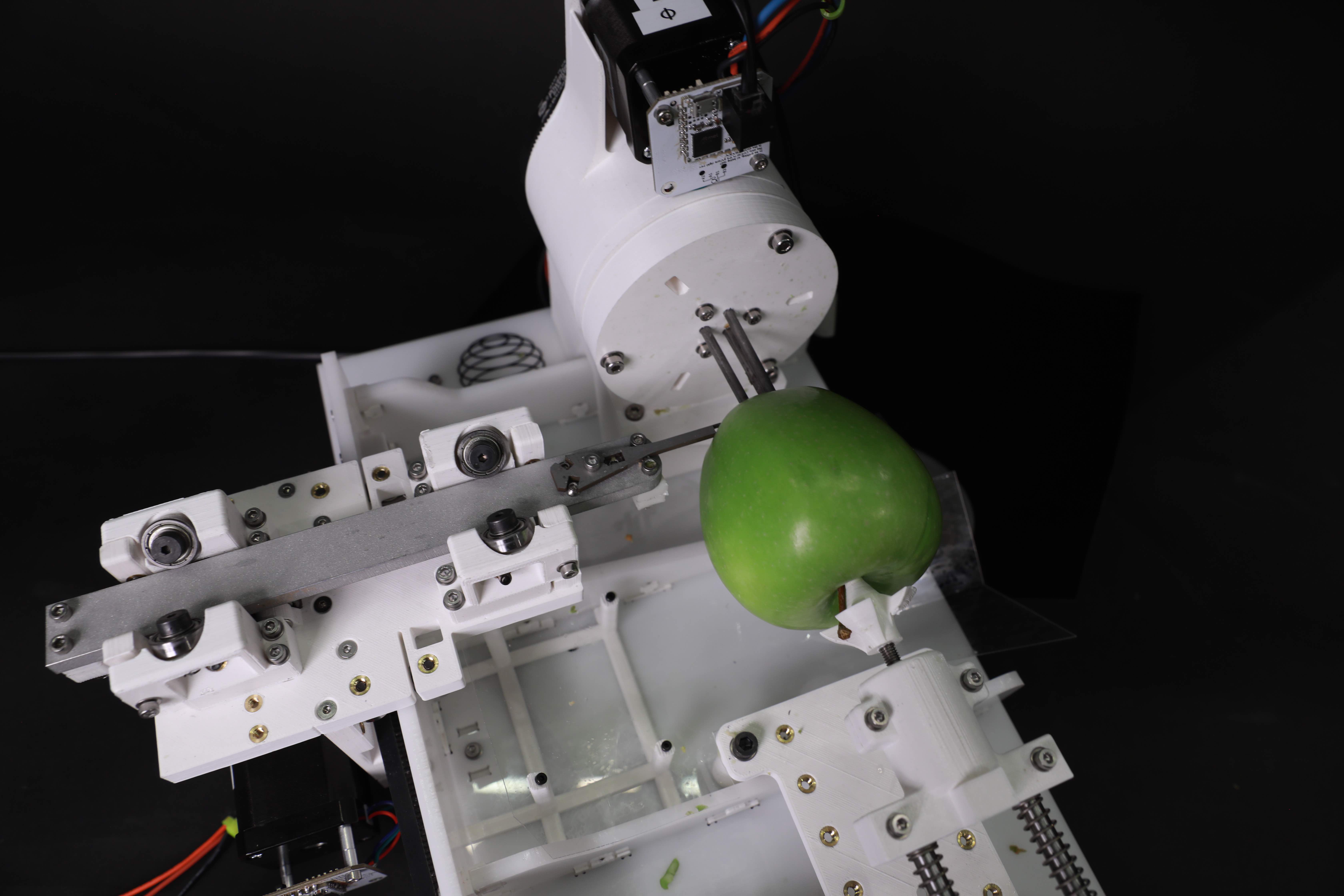
This was, by far, the most espected week, and it has been, by far, also the most intensive week. CBA team was composed by awesome talented and hardworking people and we were able to make a really nice project. We are introducing to the work the APFELSTRUDER!
I was the CAD designer of the team, inside the design and assembly group. Also I was a member of the assembly team. Please, find here the documentation of all this crazy week. In this webpage, you will find only a detail explanation of how do I came with this form for the machine and the design proces followed to bring this beauty into live.
Wednesday night. First hours of Machine Week. After deciding in a group brainstorming that we were going to make an apple lathe, we started thinking about the concept of it. We made some research on how the distribution of the axis were going to be and we decided to make it as simple as possible. We decided to have a linear carriage that will hold the tool over a normal linear axis and an independent rotary axis (independent in a mechanical way, not in code!) The first step was to download the files given by Jake and start retrofitting them! We decided to extend the proposed triangular beams and generate other with a funky shape, able to hold the load of the main beam and able to provide to us a flat floor. Also, It was noticed that we could correct the deformation of the linearity of Jakes axis by adding two new external ribs, outside the linear motion of the x axis.
To know the real dimensions, it was decided to determine the normal shape of an apple and which should be our available motion combining all axis.
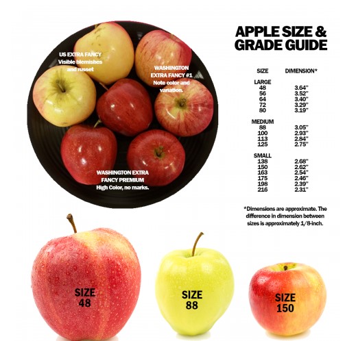
As it can be seen, even the biggest apple gave us a small range, so we decided to increase the volume to possibly be able to mill also a zucchini or even a potato!
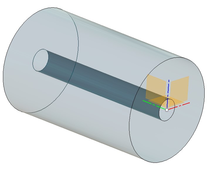
The dimensions of the cylinder we are available to operate with are 95mm ext, 20mm int and 150mm of depth. Once we had this information, the design process started. We took Jake axis and we start modifying it. We calculated, reduced and reinforced the main traveler axis due to on it, we were going to place our carriage responsible of holding the tool.
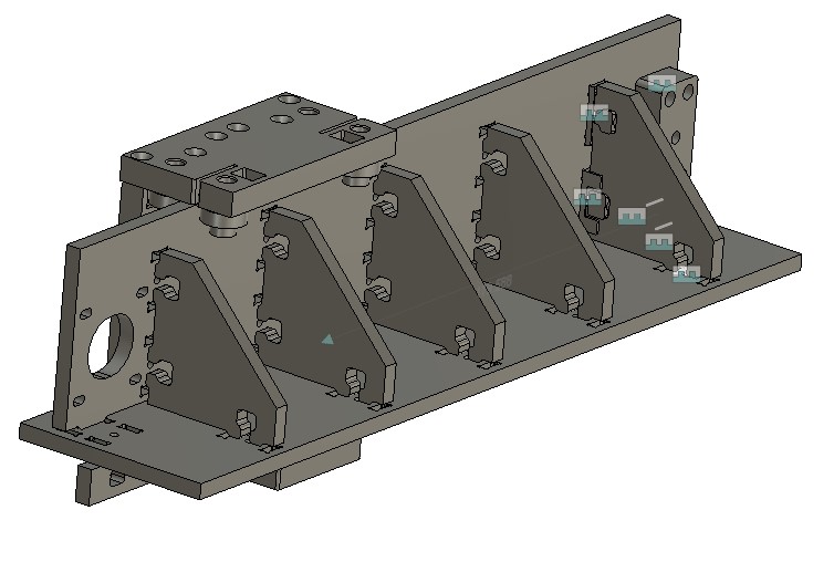
After that, we decided to start elongating , reducing the number of ribs and changing the rectangular base into a cuadrangular base as the image shows
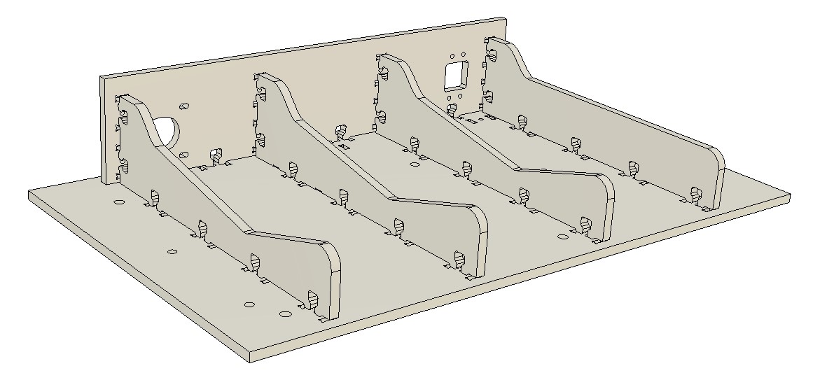
We were able to determine the position of the workplace and star determining how the toll carriage was going to look like. We needed to elongate the upper part of the C clamp in order to have surface and inertia to hold the tool loads. Also, we always had in mind a feasible manufacturing and assy possible. This is the final design of the linear carriage with the new motor holder for the extra axis we are going to add.
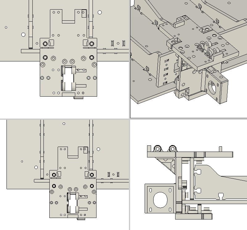
After this, it was decided in the daily meeting that for the next day we will provide the team a cardboard mockup. Jakes provides us with a rotatory element of his machines and we adapted the end effector to be able to hold three screws in a parallel axis that the rotary axis. In every moment of this project, designing was immediately followed of manufacturing to be able to be as agile as possible. Around 100hr of printing has been done so it was needed to use as many printers as possible.
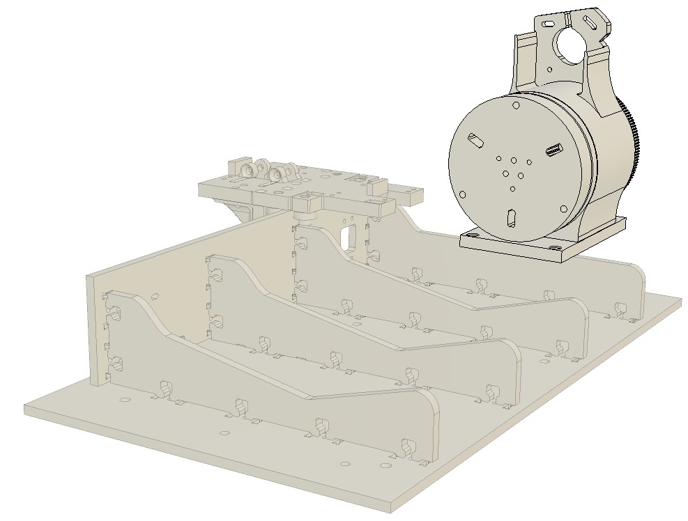
It was decided then the nomenclature of the axis for future references. After having a clear concept of the space we are going to be able to carve, more specific geometric values were decided and calculated, as the maximum and minimum tool length, tool holding width, kinematic coupling values, the width of the carrier and the range of the carrier based on the biggest apple we can put on the machine. Thanks to this study, the result of the final shape of the tool carriage is the following:
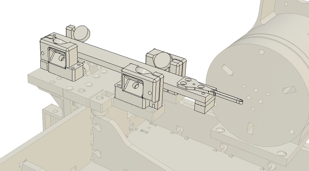
As it can be seen, it was modeled from scratch but based on a design that moves a plate using 8 bearings rotated 45 degrees so the square plate is being guided tangentially by them. This smooth system allows the carriage to move with a nice clearance below it, letting us to install the motion belt just under it. The mechanism used to fix the belt is also a mechanical stop of the axis as a extra security item. Once this element was done, it was time to provide more stability to the motion. It was decided to create a passive rotatory element aligned with the center of rotation of Z, that provided us stability by holding the apple in the opposite side than the motion is given. This device must accomplish all the possible apples lengths so a stepped base was given but holding a passive rotatory element pushed by springs that will works only in compression and will cover the full range of the axis.
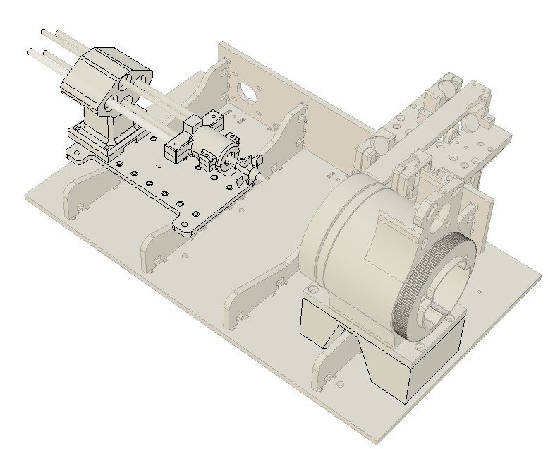
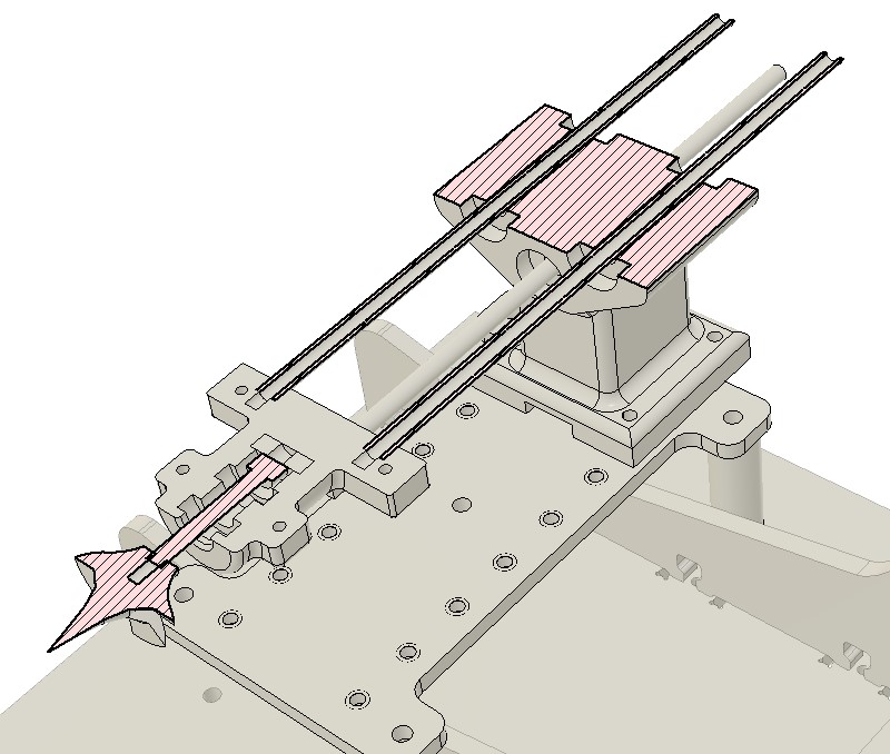
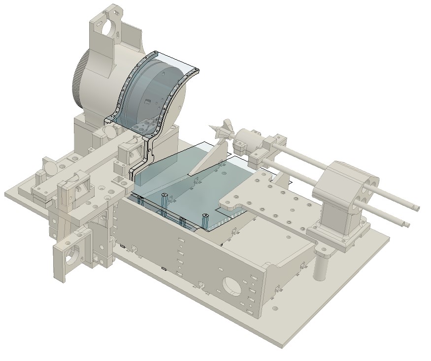
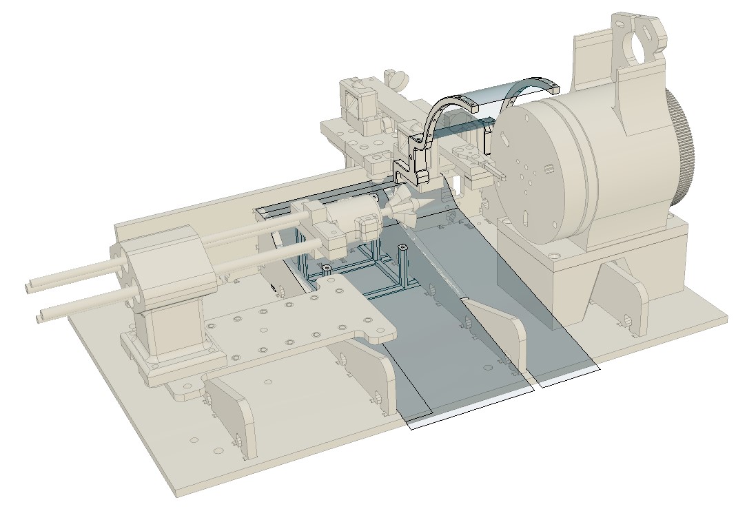
A set of protection was decided to be designed in order to avoid the apple juice and meat to reach the engines and to keep the machine clean. It was designed in a single curvature element so they can be unrolled and manufactured in a transparent thin plastic and held in PLA beams as the image shows:
 back to menu>