Thin Film Microphone
Programming SAMD11 / Wildcard Week
For my project I decided to use the SAMD11 as the sampling microchip for the audio signal. The idea is to visualize the sound using the sampler. So I used the wildcard week as an opportunity to learn how to work with the SAMD11 embedded board.
First I attended a workshop led by Erik on the samd51 showing the workflow for programming the SAMD51 using the ICE programmer and openocd. Erik Hello World Datasheet Wildcard Page Open OCD
Info from Workshop
1. Download Open OCD to program ARM- Version from Brew works for SAMD11s
- OpenOCD is the AVRDude of ATMEL chips
- Download with brew $ brew open ocd
2. Programming with OpenOCD
- Use 2x5 header and power the board over USB, FTDI to connect the ICE programmer to the board.
- Follow steps on https://gitlab.cba.mit.edu/pub/hello-world/atsamd51/tree/master/blink-openocd
3. Debugging code on gbd
interface cmsis-dap <- compute rot programmer set transport swd <- programmer to board atsame5 bootloader 0 <- unprotect the bootloader program bootloader-feather_m4-v3.7.0.bin verify <- what's the bootloader atsame5 bootloader 16384 <- don't overwrite the bootloader reset
Prorgramming SAMD11 on Neil's board
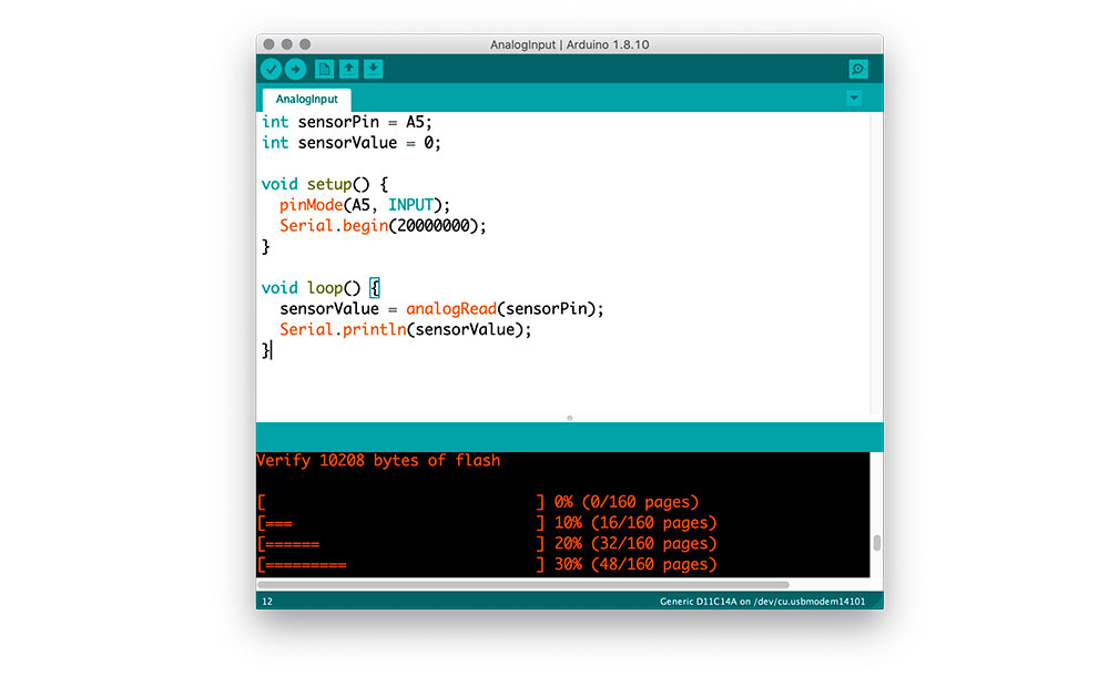
Since I am going to use the SAMD11 for my final project I decided to do 2 tests. One was to simply mill the hello world USB board from Neil and connect a wire to the A5 pin, go through the flow to program the SAMD11 using Arduino and do an analogRead on the pin to see if I could get some data
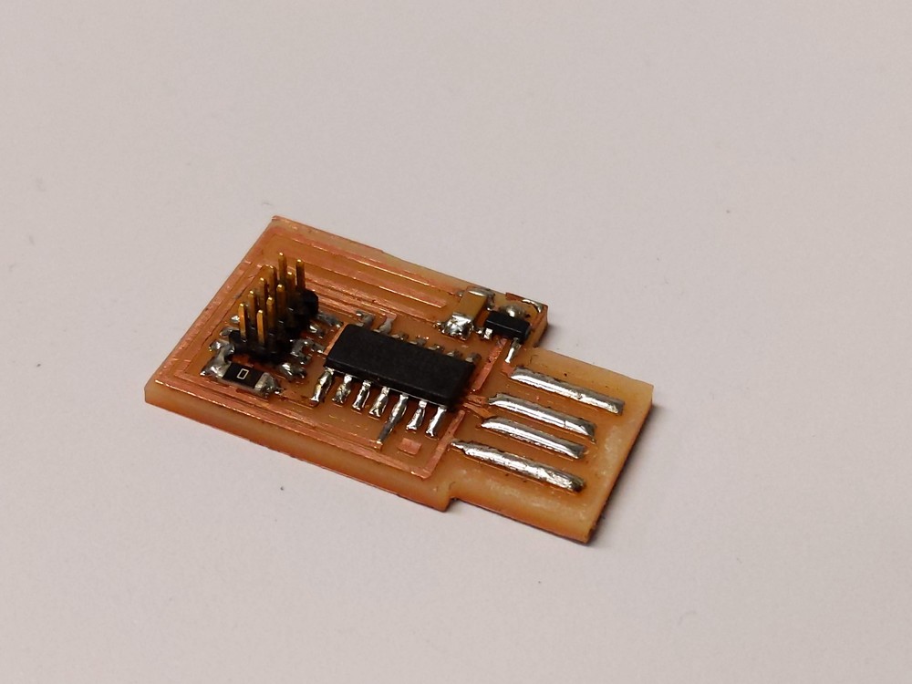
My first approach was to mill Neil's board and perform some tests with the ADC to check for it's response to higher frequencies (~10Khz). So as a first step I milled Neil's board and stuffed it with the components.<
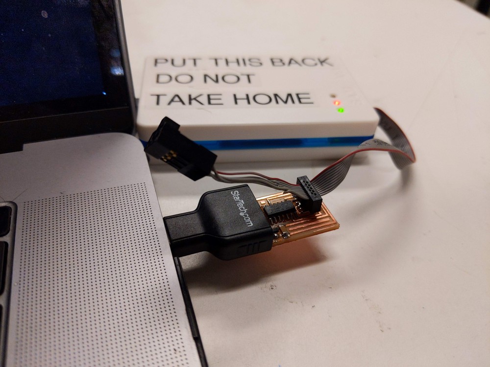
I then programmed the board
 by running openocd in the configuration file provided by Erik during the Wildcard session. We started running into a an issue that the board would be programmed but when uploading the first sketch from Arduino it would disappear from the serial port. After checking connections, replacing the chip and discussing ideas with Daniel, I ran open ocd with the unlockbootloader.cfg file before flashing the bootloader. After this I then uploaded the Arduino sketch and the board was visible on serial.
I ran my first test which was to just open a serial connection and print the work test to the serial port
I then connected the board to a function generator and started performing some tests to see what was the limit that I could sample a signal without loosing resolution or "garbling" the input.Below you can see me testing the board and increasing the frequency.
Here are some screenshots from the Arduino monitor. One thing that wasn't clear to me that i changed the serial speed on the serial print and monitor but that didn't seem to affect the output in any way, even if the serial speed was mismatched in my program and in the Arduino I would get the same result.
Frequency: 100Hz
Frequency: 10Khz
Frequency: 15Khz
Frequency: 20Khz
Lastly I performed a test of connecting Neil's board to my analog circuit (see electronics for more detail) and see if I could see output. The good news is that I can see an output - the noise seen in the monitor is due to the scaling of the monitor - you can see the amplitude changing when I make a sound.
Given Neil's board works well and I learned how to program the SAMD11 I then moved on to design and build my own board.
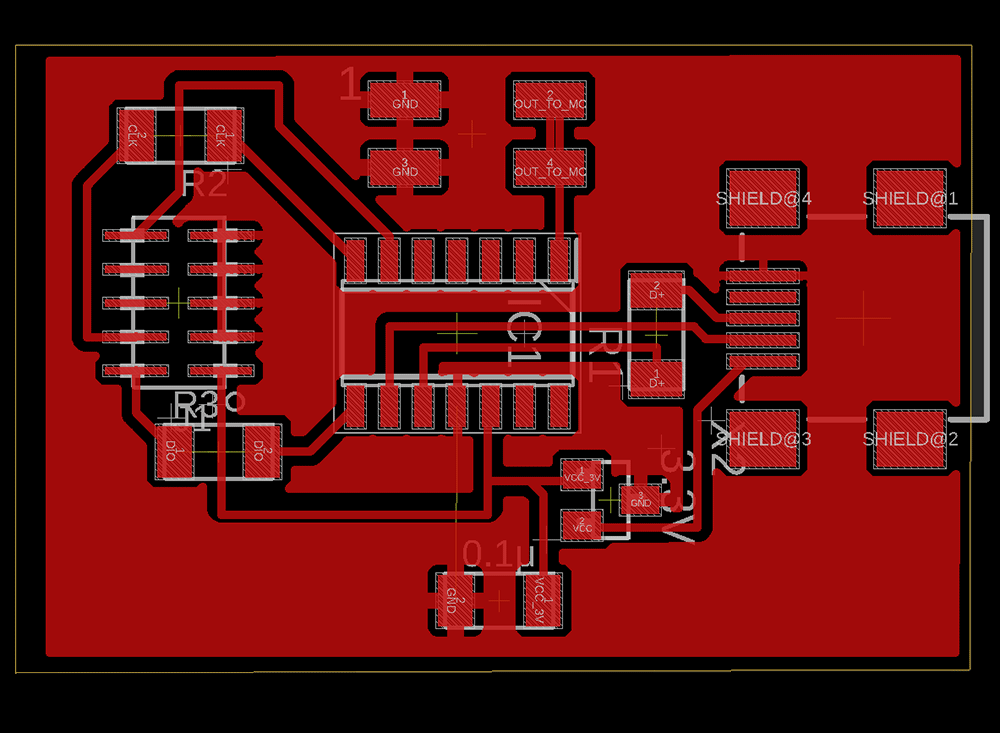
Designign my Own Board
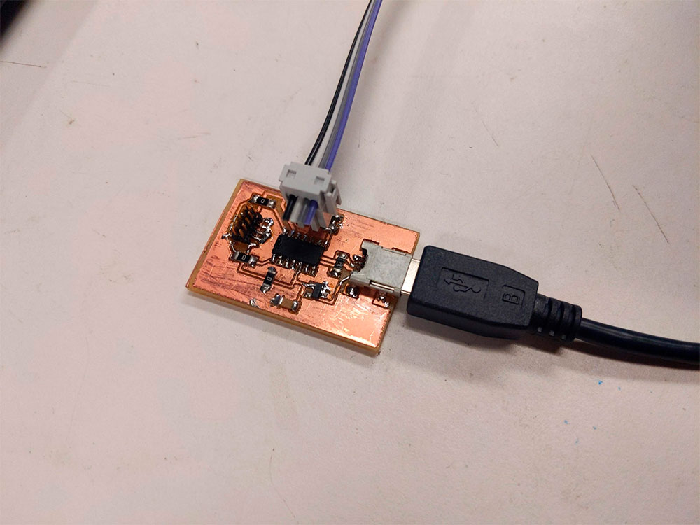
My board design is not very different from the Hello World, I added a 2x2 connector to facilitate interfaceing with the A5 pin of the SAMD11 and decided to replace the USB connector to a USBMINI connector.
To acommodate all the components I had to make use of 0KOhm resistors quite a lot - about 3-4 of them. I still find it easier to do one sided boards and use the resistors as a 2.5 alternative than going for dual sided.
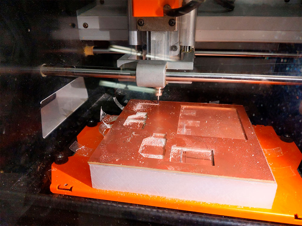
Here is the final board milled and ready to be stuffed
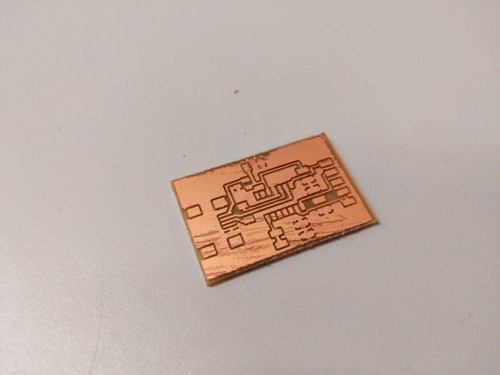
Here is the final board milled and ready to be stuffed. The milling didn't come out as great as I imagned, it took me quite a lot of time deburring it to get rid of shards of copper.
The board programmed without problems and I was able to upload the Arduino code below to the board using the Arduino IDE. Here is a final video of the ADC of my project: