Gabriella Perry
Input devices
"measure something: add a sensor to a microcontroller board that you have designed and read it"
Two weeks ago during embedded programming week I started working with input and output devices. Check out the Tangibelt project from Embedded Programming Week!
This week I wanted to test out touch/capacitive sensing. Since I had previously programmed sensors I was not super worried, but a lot ended up going wrong this week.
Two weeks ago I designed an Arduino style board that pulls all the pins on my controller out so I can test various devices without having to remake my board. I named this board a Goober since it's a silly little testing board that can do many many things. I made three Goober boards, two with an ATtiny 1614 microcontroller and one with an ATtiny 1624 microcontroller.

I like working with the ATtiny's since I can power the board and program it using one pin and a CH340 USB to TTL Converter. Usually, our lab has a CH340 convertor with a 4.7 K resister available for programming but this week, all of these programmers were nowhere to be found. I thought this wouldn't be a huge problem for two reasons. First, I wanted to buy/make my own programmer to more easily program my boards for my final project. Secondly, there are other types of these boards in the lab that theoretically worked the same way.
I found another board, the same model of the CH340 board I was previously using, and soldered a 4.7K resistor onto a wire to connect the programming pin. This is the same setup that had worked previously for the boards.... Except this time I got the error "UPDI initialization failed". I tried other kinds of boards with the same setup, and I got the same error again! I tested out using a diode, changing the resistor value, redownloading the microcontroller drivers... still no dice...


Rob Hart helped me find a temporary solution to programming my Attiny boards. The solution was to take an FTDI cable, jam a diode between the Rx and Tx pin, and then plug-in power, ground, and the Rx pin to my board....Somehow this semi-jank solution allowed me to program my board. Rob has also brought me a CH340 programmer now that I will keep safely in my electronics box for programming my final project.


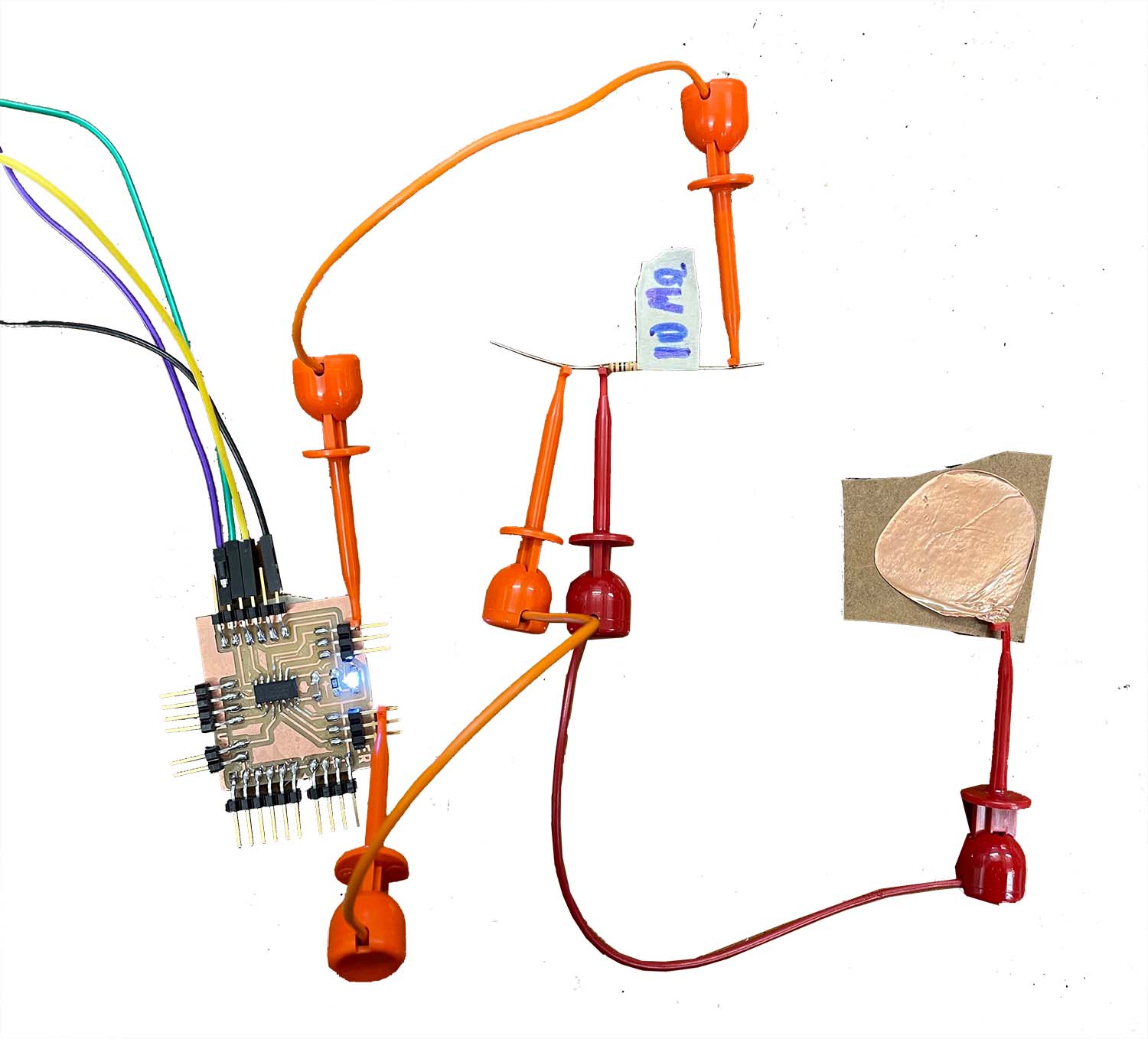
Now that I finally had a way to program my board, I used some sample code from Rob Harts sensor page, modified the pins to fit my board configuration, and programmed my board. Once that was all programmed, I connected a non-jank FTDI cord to my board via the serial pins and then connected a copper sticker and a megaohm resistor to my two pins. This worked swimmingly, and now I know how to make basic touch sensors!