
My final project needs to be able to wireless pass data from a ball to a computer or smartphone. Which means that I’ll need to get a smooth wireless networking up and running.
I don’t love the idea of my device being reliant on a wifi connection. So for my first crack I‘m going to try using an RN4871 chip to establish a Bluetooth connection. Using Bluetooth Low Energe (BLE), I should be able to send 20 byte packets, which is all I need to pass some position data.
In the lab we already had an old RN4871 breakout, so I decided to start with that, following this walkthrough.

No dice on the premade board though. It powered but the broadcast light never turned on, and I wasn’t able to detect it using the BLE Scanner App I downloaded. So the next step was to make my own board. I just used the traces and outline that Neil put on the class site.
There was a litle bounce in my board so some of my traces were a little burred, which I fixed with a razor blade. Then I had to actually stuff it, which I was freaked about because I was pretty sure the RN48701 needed to be mounted using reflow.
I‘m really not sure I did this correctly. I globbed a bunch of solder onto the pads, and then used the wick to remove the excess and leave the pads nicely tinned. I covered the bottom of my component with solder paste, which may or may not be the exact same thing as flux – I’m not sure! And finally I held down my component with tweezers and blasted the whole thing with the heat gun.
Most guides I found online said that I shouldn't blast with the heat gun for more than a minute, but in much less time than that I started to see some darkening/burning in my PCB underlayer. It’s totally possible I fried something inside of the chip.
And I didn’t really see beads of solder emerge from under my component ... but it did hold down tightly. So for insurance, I non-reflow soldered the six pads that actually had traces. Here’s the final result, after stuffing the rest of the board.

So I was a little shaky on the whole thing. And yet! When I powered the board, all the sudden in my scanner app there was BLE-1709, and it was connectable.

The ”BLE” was a good sign that this was the chip I was looking for, and also the signal got strong I was pretty sure this was my chip, and to confirm I scanned the mini QR code that’s on top of each RN4871. It reports back some sort of unique ID which did, in fact, end with 1709.
But it was too good to be true. I moved on to the next stage of the walkthrough, and tried to communicate with my bluetooth device through a serial connection so I could configure it. The commands are really nicely laid out on an old CBA page from Will Langford. When I typed $$$ with no line ending, I didn’t get any response.
I figured that this is maybe because I fried my RN4871 with the heat gun. So I decided to make a new chip, with two added indicators lights per the suggestion of Rob Hart’s page. The first light indicates that the board is powered, and the second starts blinking when the BLE connects to a device.
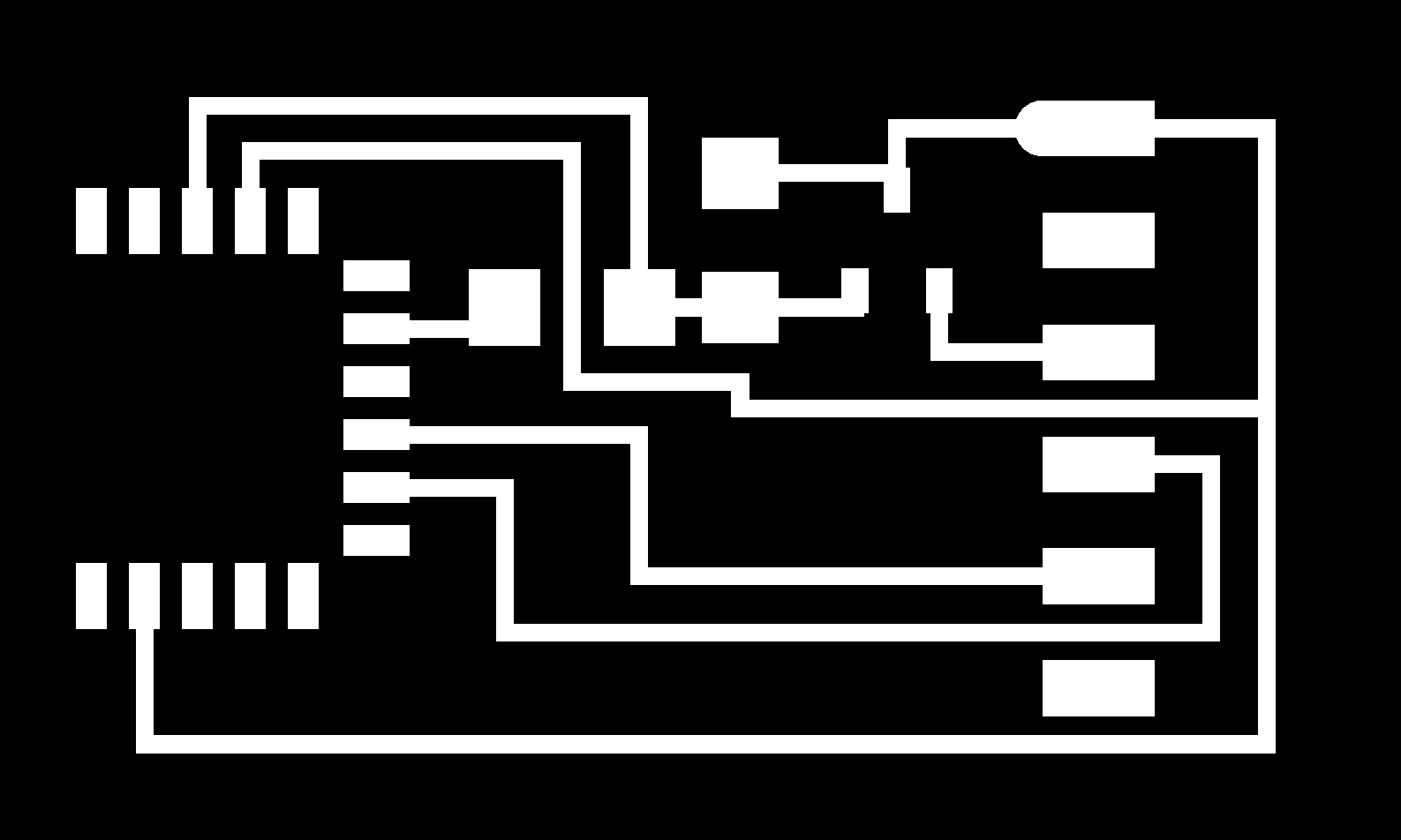
Here’s my layout, which did require a jump resistor. I hate the pin layout of the RN4871 – would be so much simpler if the top GND and VBAT pins were reversed. Or if it just had one ground pin?

Based on another student example – Gil Sunshine’s from 2020 – I skipped reflow and tried to just solder my chip down like normal, after tinning the pads.
I wasn’t super happy with the connections I was making, particularly on one of my grounds. My board powered on great, but the bluetooth would only work when I help the RN4871 down hard with my thumb.

I was right about the soldering. This was disheartening ... except that when I was holding it down, my board was actually programmable! Here’s me running the commands, which sets the device to UART service and renames it.

I got a hand from Rob to fix my soldering. I was actually a lot closer than I thought – I just needed to get more solder up higher in the ”notches” of the RN4871. I was thinking that the solder was supposed to flow more underneath to the exposed copper on the bottom of the chip. After about 20 seconds of masterful solder work from Rob, it was working awesome.
So it was time to send commands. From the BLE Scanner app on my phone, I passed a text message that said ”hi my name is Reuben”.

And in my serial terminal, there it was!

That counts as networking. I didn’t get quite as far as I wanted this week, and I still have to figure out how to pass accelerometer data to the RN4871 and then send that message, instead of just receiving messages. But the hardware portion is done.
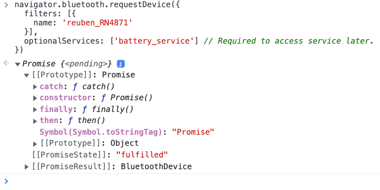
I did make one more advancement. I want my final interface to be a webpage, not a phone app, which means I needed to figure out how to enable bluetooth data in a browser setting. Two guides were helpful here, this broader one from Web.dev and this Heart Monitor demo.
In Chrome, I was able to search for my Bluetooth device by name, and successfully connect to it. I wasn’t passing data or anything but an important start.
Files: Here are the traces and outlines for my final RN4871 board. All my code this week was just copying and pasting so I don’t have anything else to share.
Final note: If you’re using this page as a guide, I made a lot more progress that’s recorded on my Week 12 and final project pages. Check out the entries for Week 12 and Dec. 5.