Week 10
Networking and Communications
Bluetooth Board
This week I decided to make a board for bluetooth communication based on the RN4871 bluetooth module. The board itself was based on Neil's
RN4871 board. On top of this baseline design I added two LEDs on the reccomendation of Rob Hart. One LED indicates that power is actually
getting to the board and the other indicates connectivityt. I'm quite glad I included these because I had flaws in my design that these two LEDs helped in identifying. Also, shoutout to Rodrigo Escandón Cesarman and Jim
Peraino from previous years. Their pages were helpful this week.
Below is my initial schematic. There are two problems with it. First, I'm not actually sending power to the board. This is not the first time I've done this but I think I have now actually (hopefully) learned my lesson. Second, I had my TX
and RX mixed
up on the FTDI cable. I haven't been using FTDI because I've mostly been using the SAMD chips. Basically, the "receive" (RX) on the FTDI cable needs to be connected to the "transmit" (TX) on the chip. This of course makes sense, but I was
thrown off by the labeling in the schematic and connected the TX on the chip to TX on the cable.
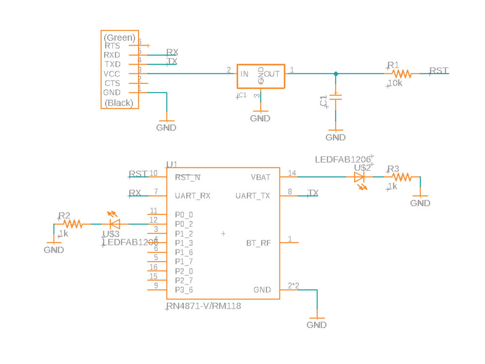 Problematic schematic.
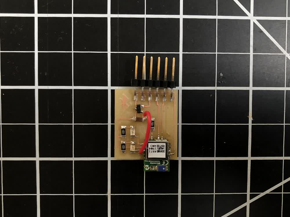 Problematic board.
Soldering the RN4871 is a bit tricky. I started by using a reflow technique but ultimately found it easier and more reliable to just solder by hand using a fine point solder tip in this case.
I realized I wasn't getting power to the board thanks to the power indicating LED and added a little jumper wire shown above. However, when trying to communicate with the chip with pyserial's miniterm I was just getting no response. After
some confusion I realized the mistake and updated the schematic and board design seen below. Note that this week I made boards in the architecture shop on the Roland SRM-20.
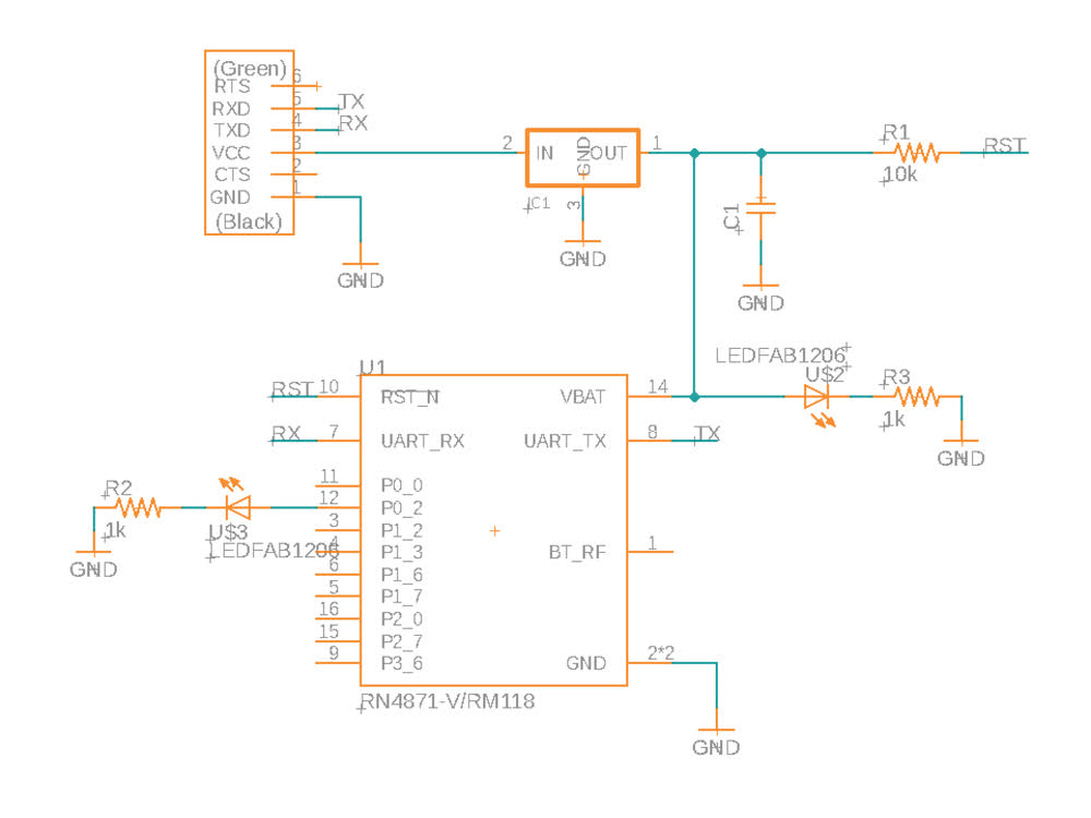 Updated schematic.
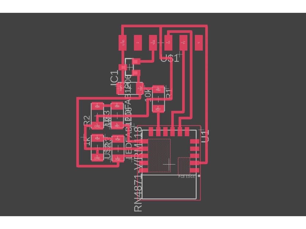 Updated board.
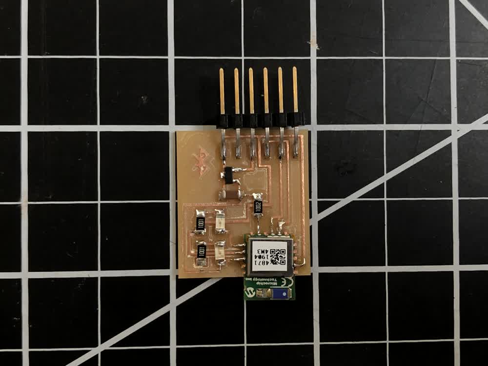 Final board.
Once I had the new board milled and stuffed things were pretty straightforward. First, I connected the board to my laptop via FTDI cable. Then I used Bluetility to make contact with the
board. The red LED blinking below indicates that a connection has been made.
Connection!
I used the miniterm tool from pyserial to read messages sent from Bluetility to the chip. Once installed, "sudo miniterm.py" will list available serial ports to choose
from.
Once the terminal is running I entered the commands on the left. They don't show up unless echoing is turned on with the "+" command. "SN,GILRN4871" changes the name of the chip to make it easier to find.
Sending messages over bluetooth!
File: 201119_traces.png
File: 201119_outline.png