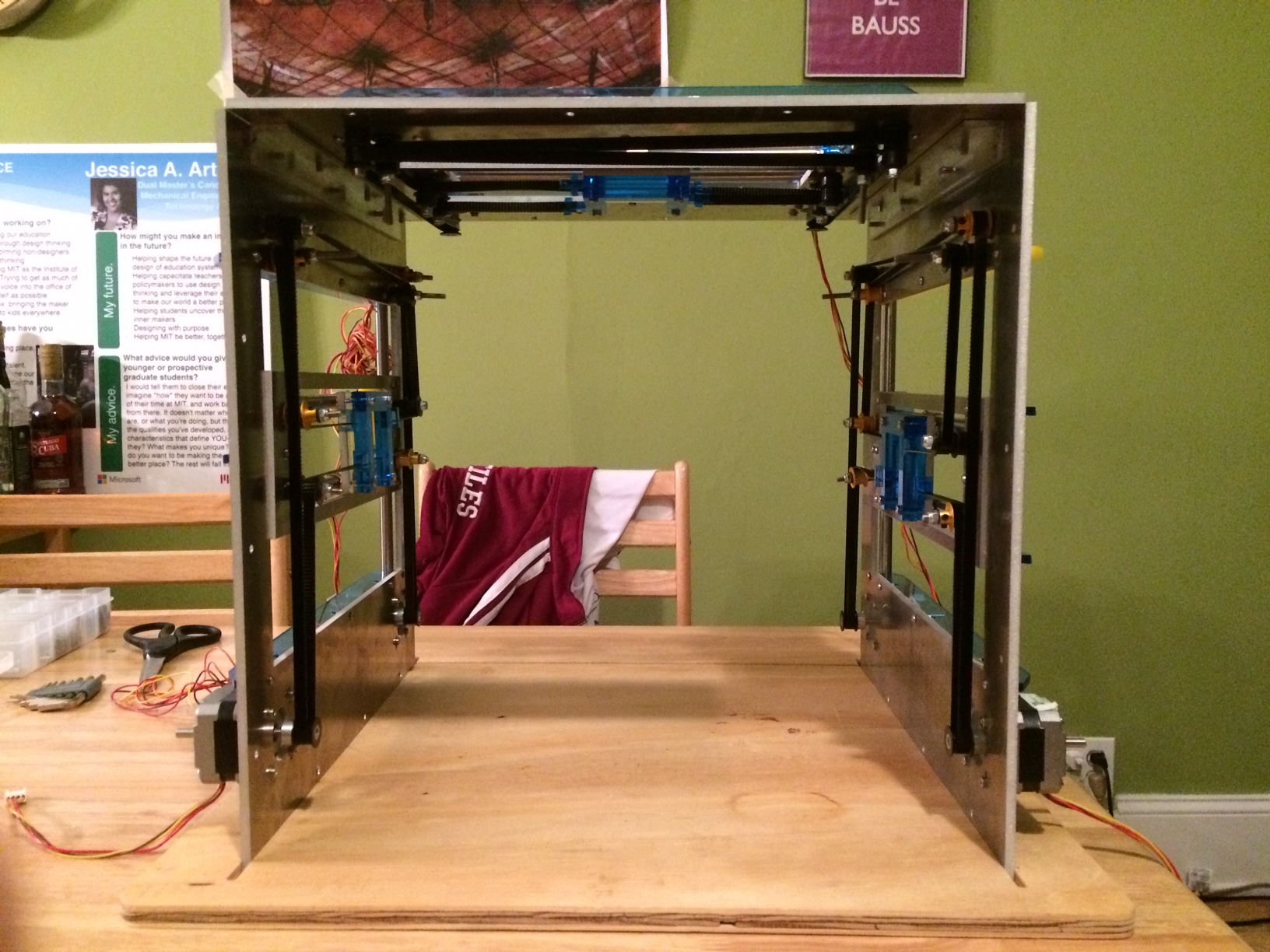
The system makes use of the following components in its assembly: at least 3 stages (CoreXY systems), L-brackets for any interfaces, a wooden base board, choice of base plate, Gestalt Nodes and choice of end effector.
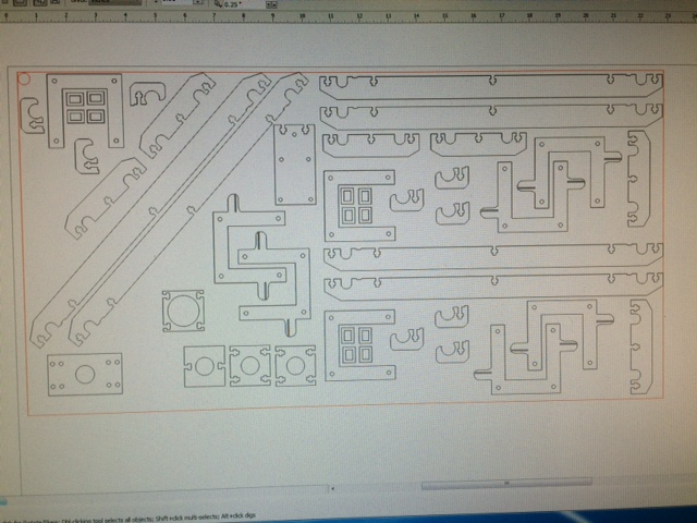
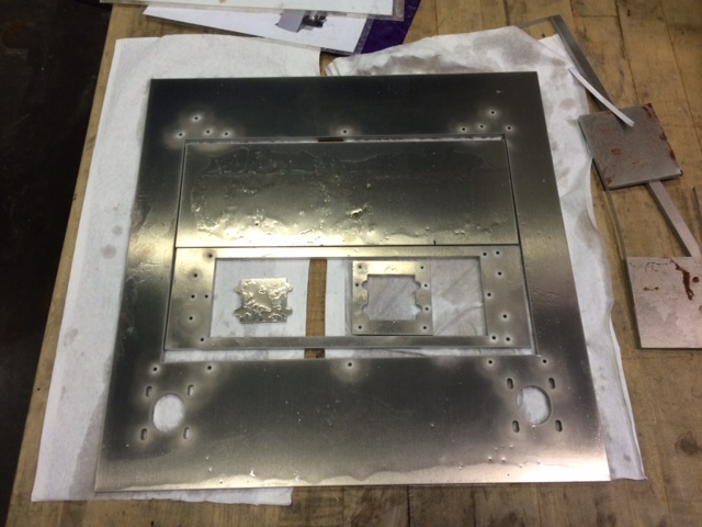
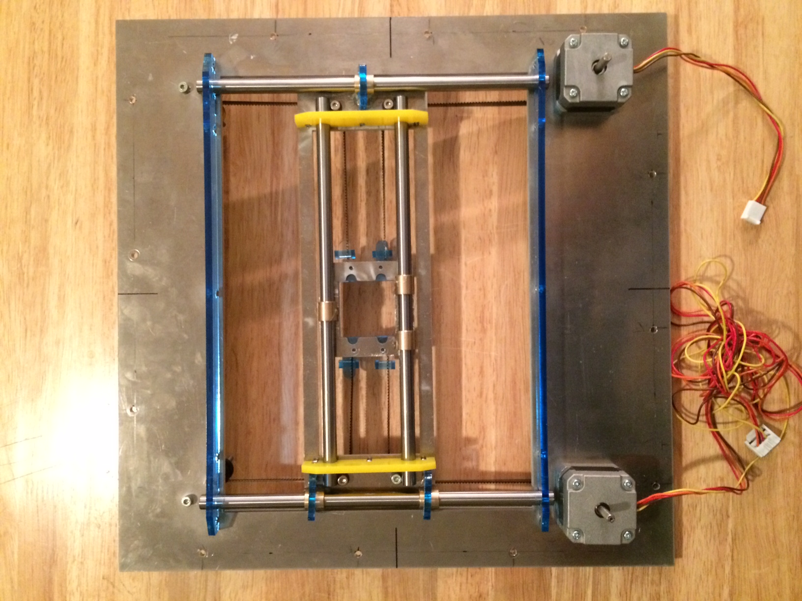
Laser cut components that allows for end effector mounting, x and y gantry movement, and the holding of the aluminum rods. I then waterjet aluminum to create the entire base and the x and y pieces.
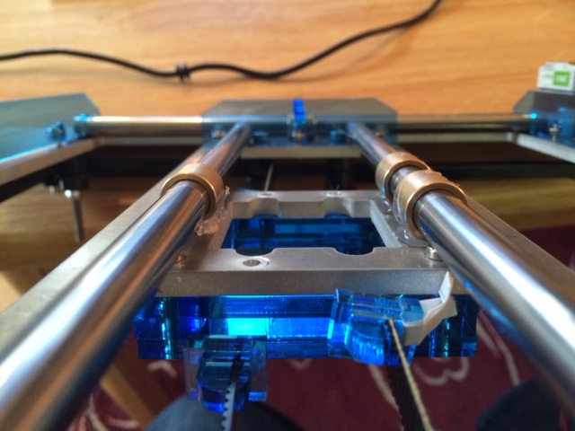
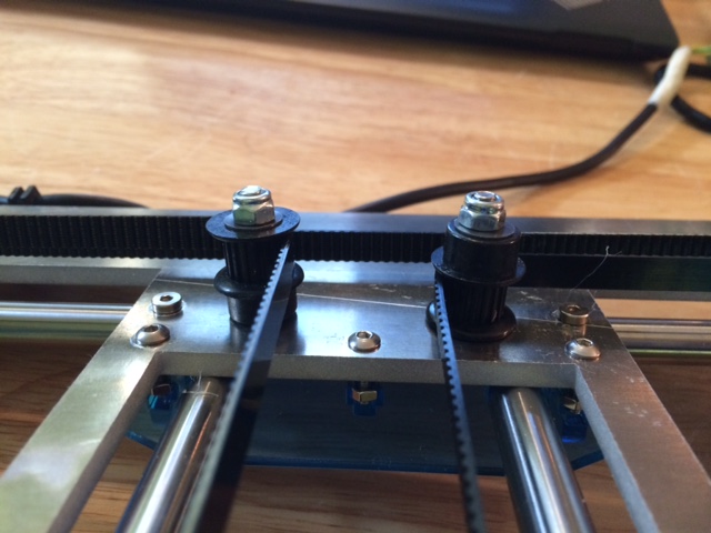
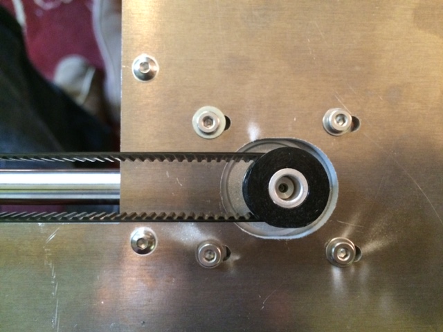
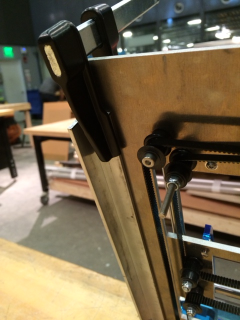
The x and y pieces are hot glued to bushings on the aluminum rods. The belts are held onto the gantry by using teeth and using an acrylic square to squish the teeth together. The gantry itself is moved with two stepper motors in an hbot configuration. The plastic pulleys keep the belt in tension and move the gantry accordingly.
The new dxf files scale the aluminum plate to 14.32 inches. That sounds random, but that allows an inch perimeter around all components (including components that move) and allows clearance for
In addition to small changes in the acrylic due to the scaling, the modular corexys also have offset from center holes on all four sides. This offset provides the ability for any two sides of any two stages to connect.
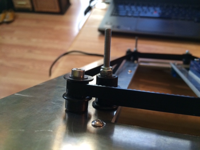
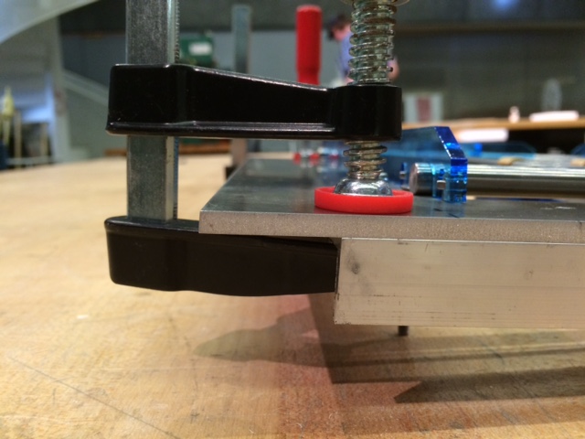
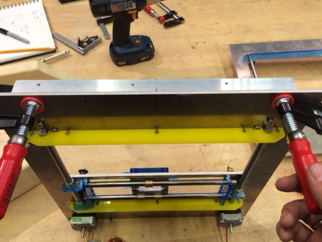
3/4 inch wide L brackets were used to join multiple stages of corexys. The offset provides clearance for the thumb screws. Holes were created by clamping the brackets to a stage, but they work on all stages. Brackets were tapped to fit M4 screws.
Base board is made out plywood. The slit were made on the shot bot. The width is made so stages fit snug into it without external mounts. Three slits are currently on the board. This allows for the mounting of the configurations proposed in the inspiration part of this page (4 axis, hot wire cutting, and pseudo 5 axis).


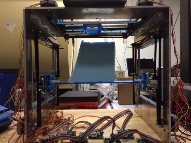
Base plates are made out of acrylic and come in widths of 2, 3 and 5 inches. All are 12 inches long. Wider base plates allows for larger machining area since the top stage can move opposite of base plate. The total machinable area is now double the single axis range of a stage. (might need a picture to explain this better. Ask me!
Narrow base plates are used when you want to take full advantage of the rotating axis, allowing the piece to get closer to the machining tool head. The narrower the bed, the closer to 90 degrees you can machine.
Base plates have a hole at each end to allow a simple mount to the stage gantries. One side is controlled by a stepper motor while the other is passive.
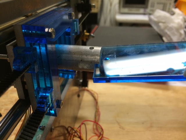
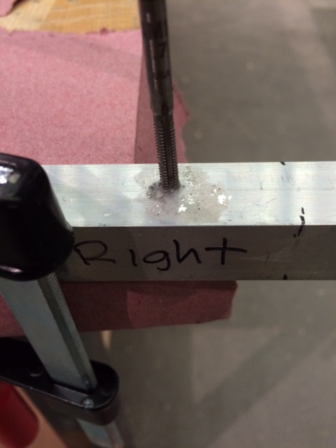
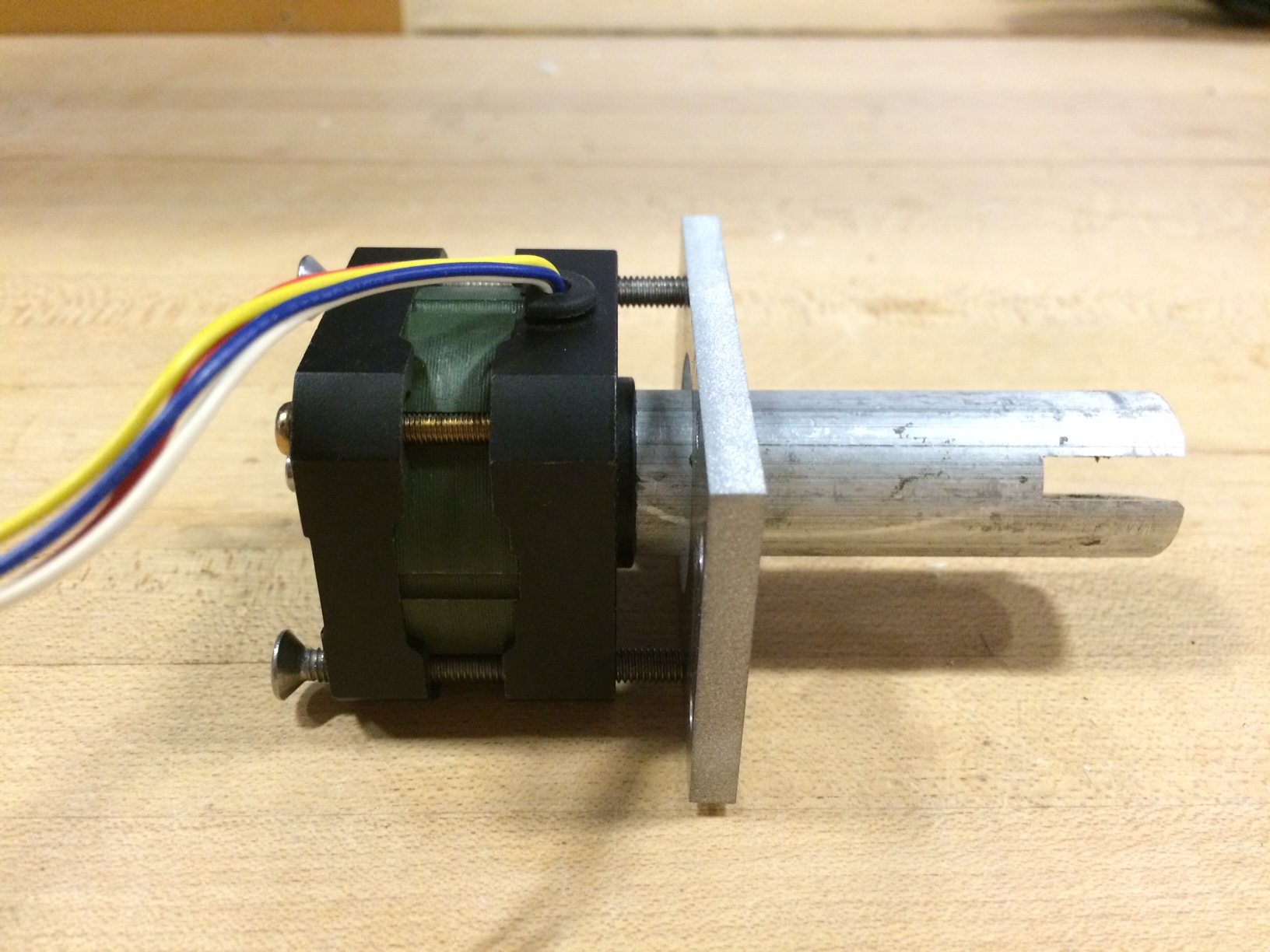
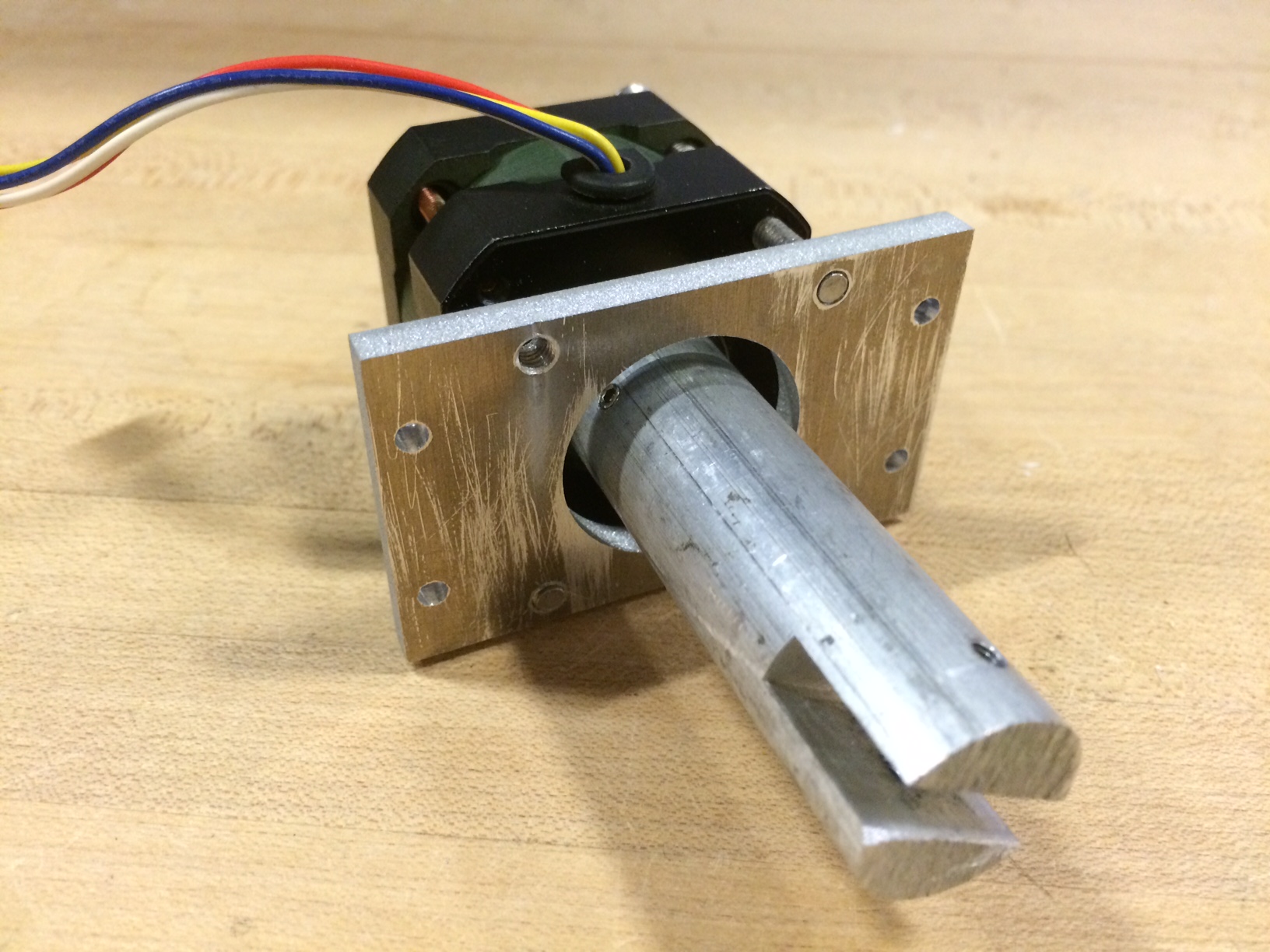
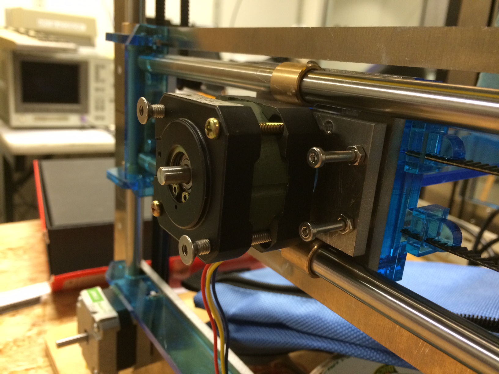
The rotation axis used a stepper motor attached to one end, and a passive 3/4 inch aluminum rod on the other end. Slits the size of the acrylic sheets were milled, and a lath was used to couple the rod with the stepper motor shaft. The rod was tapped to allow a set screw to firmly grasp the shaft.
A small aluminum plate was waterjet to permit mounting to the gantry. In future iterations, the size of the stepper motor should be specified to scale the gantry appropriately. It stuck a little, and mickey mousing nuts and screws allows for an ok mount.
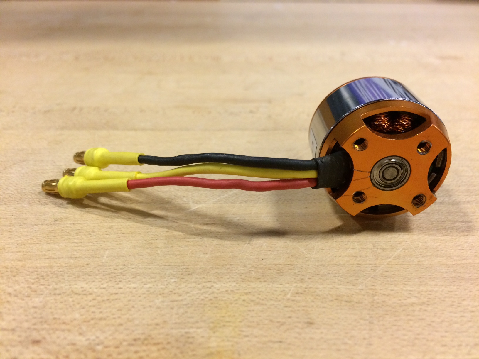
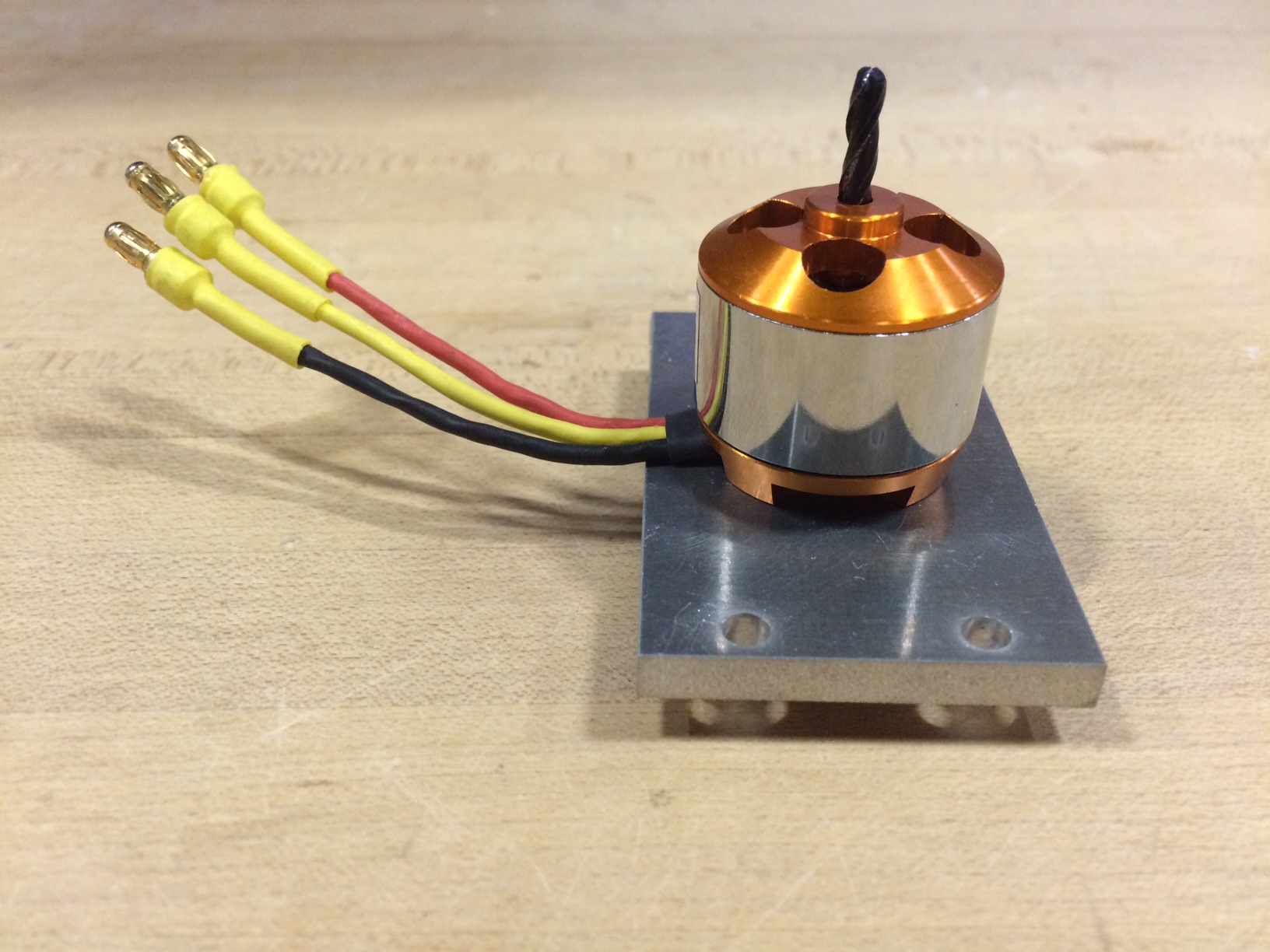
Thanks to same for helping out with this. Use a brushless motor from HobbyKing and an ESC (electronic speed control) to control speed. Programming the ESC is fun, because it makes lots of noises. You control it like a servo, although it needs it own separate power supply.
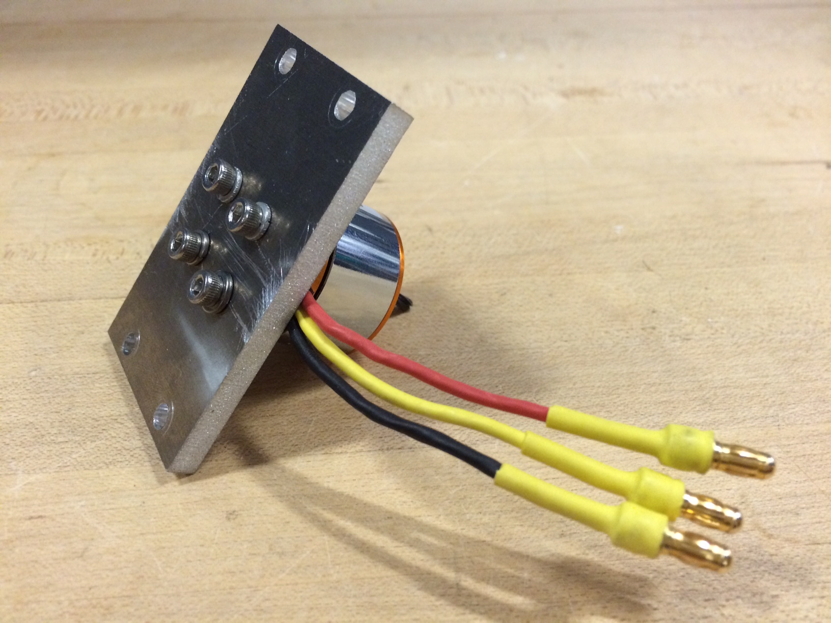
Similarly to the stepper motor, this was mounted with an aluminum plate that was waterjetted.

Nadya rocks!