<-- HTMSTMAA
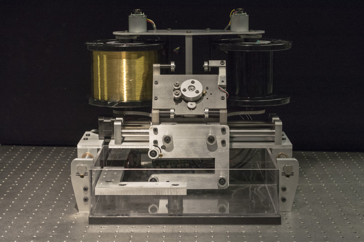
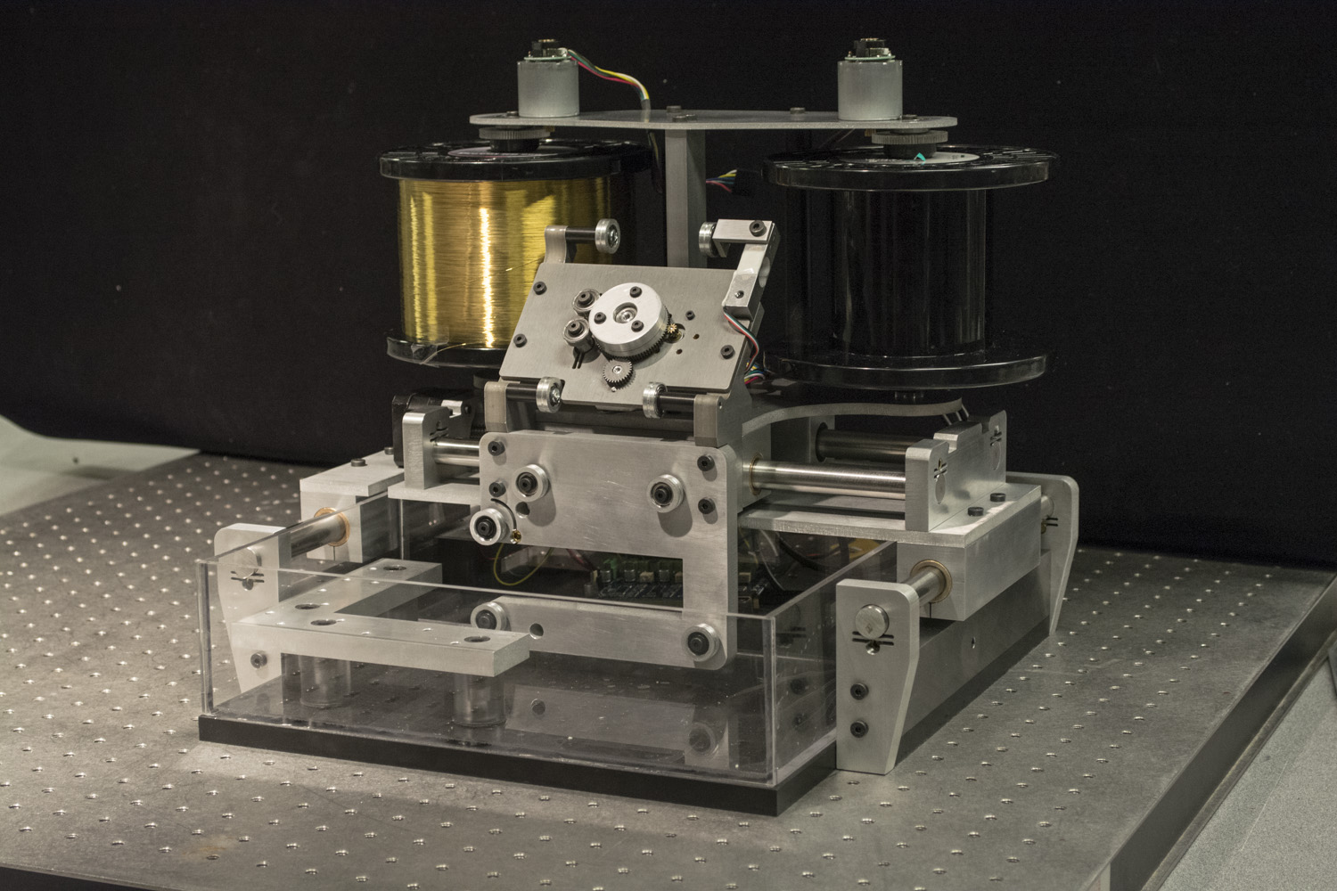
In the past few weeks I've been thinking about how to make a desktop wire-EDM. Now it's made...
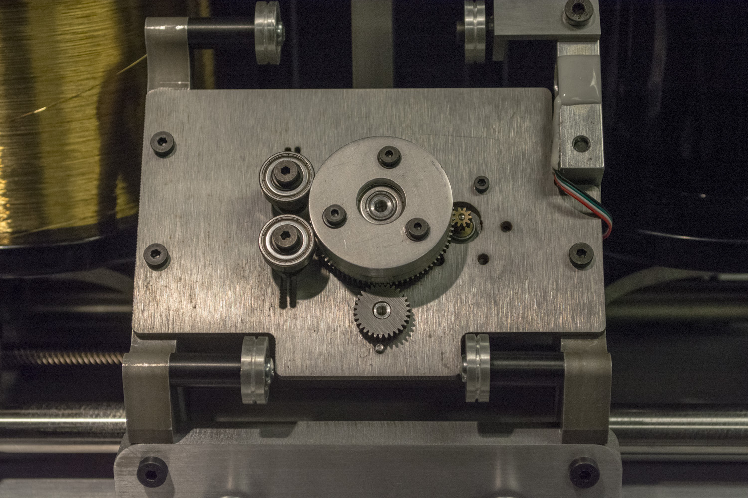
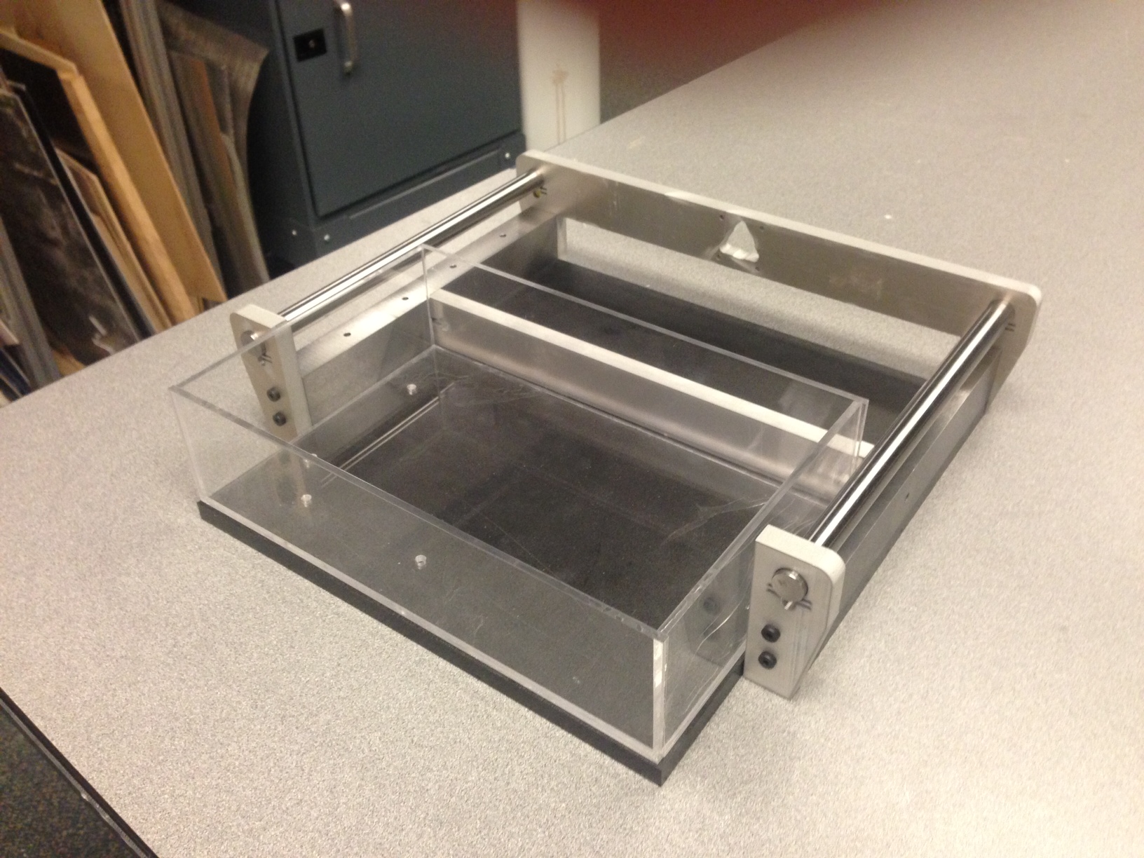
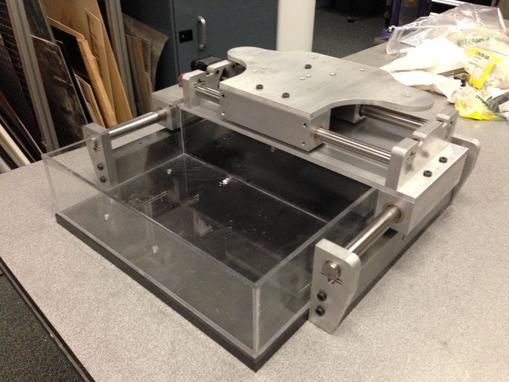
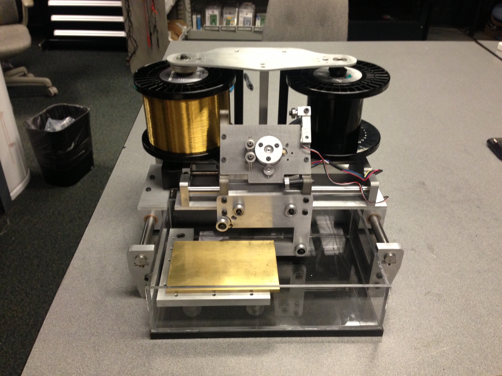
At the center of the machine is the wire feed mechanism I made in a prior week. It's responsible for controlling the wire speed and tension.
The wire passes through a few pulleys before presenting the cutting length of wire to the workpiece. The wire is then sent back over the feed mechansim and onto a take-up spool.
One technique I wanted to try out in this design was the use of tapered plugs to contrain the shafts in the plate. This was inspired by Dan Gelbart who has an awesome series of fabrication related videos. The design worked okay... I think with another iteration of tweaking parameters it would constrain them more rigidly. For now it is completely sufficient for this application but may not stand up to hammer blows.
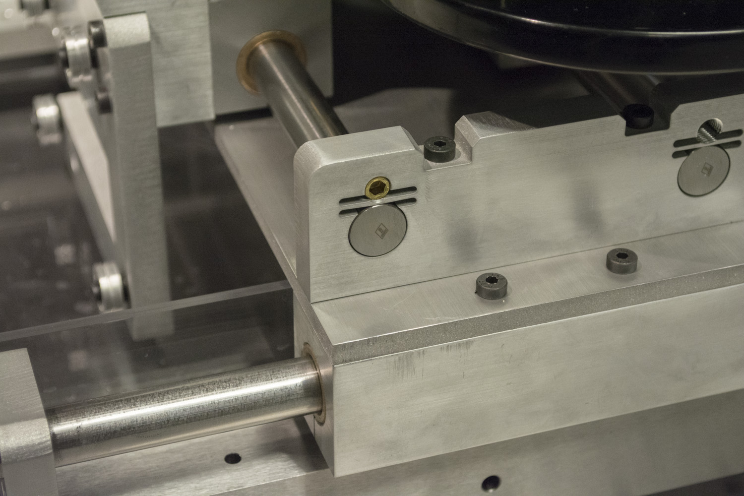
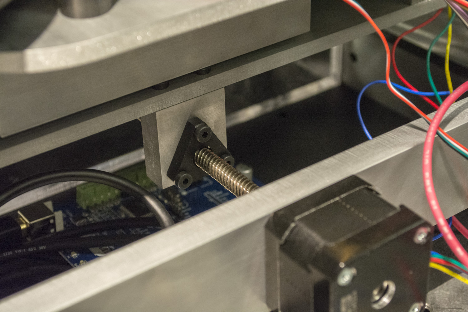
Nadya kindly let me use one of her fancy steppers with an integrated leadscrew. The 8mm of travel per rotation might be slightly large for my application but I think the best way to verify that is by testing it.
Most of the structure is made from steel and aluminum and was machined using a variety machines including the waterjet, mill, and lathe.
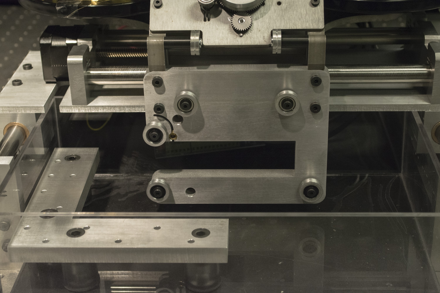
Given that this machine had to be fabricated entirely in the course of a week, I tried to design it to be as simple to make as possible. Some parts of the machine succeeded in this respect, while others posed a much harder fabrication challenge than I had hoped for. The precision ground steel uprights which give the machine its sturdiness, for example, called for tapped holes in the end of their 10.5" length. This required some hacky (clever?) fixturing.
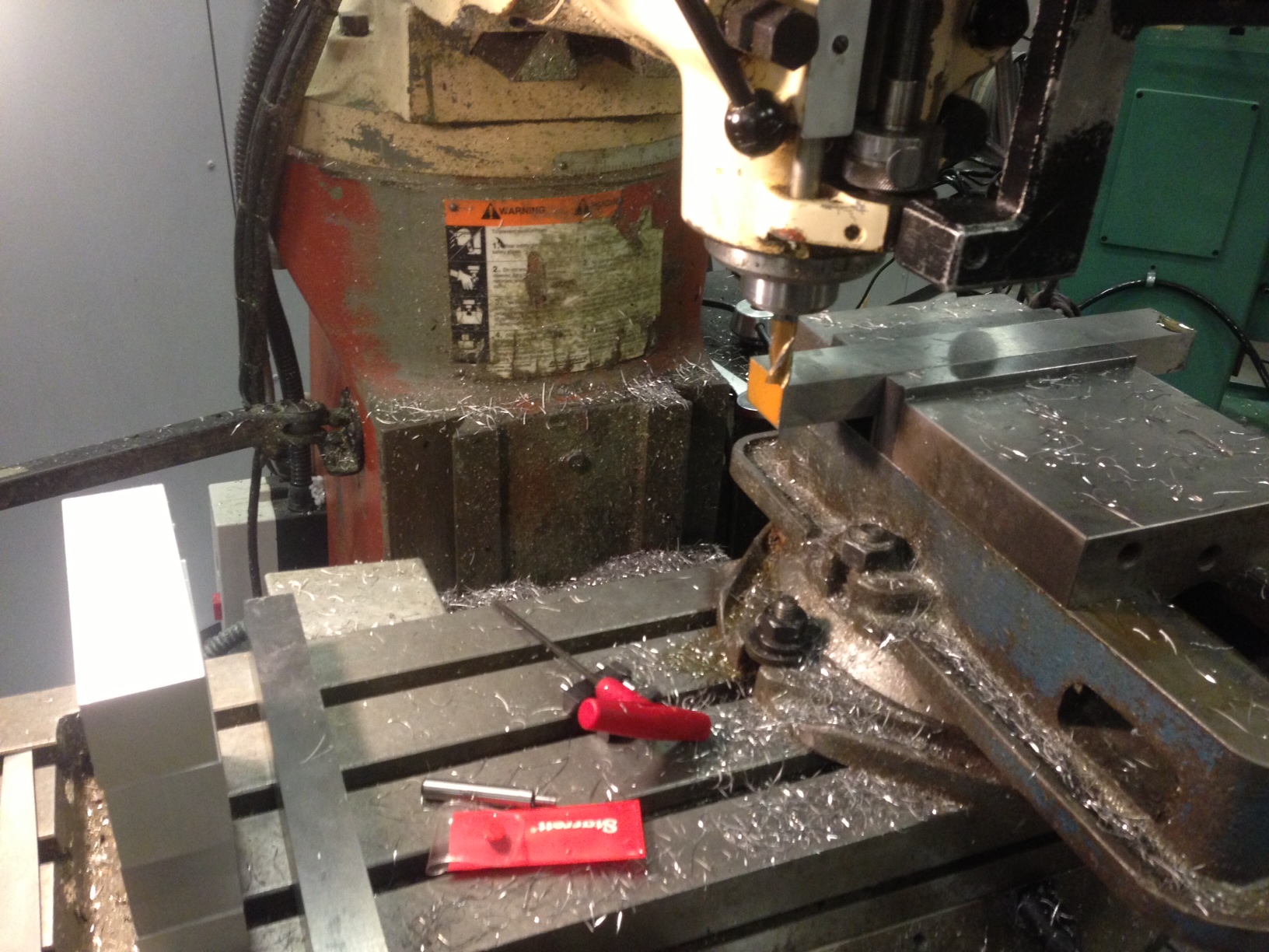
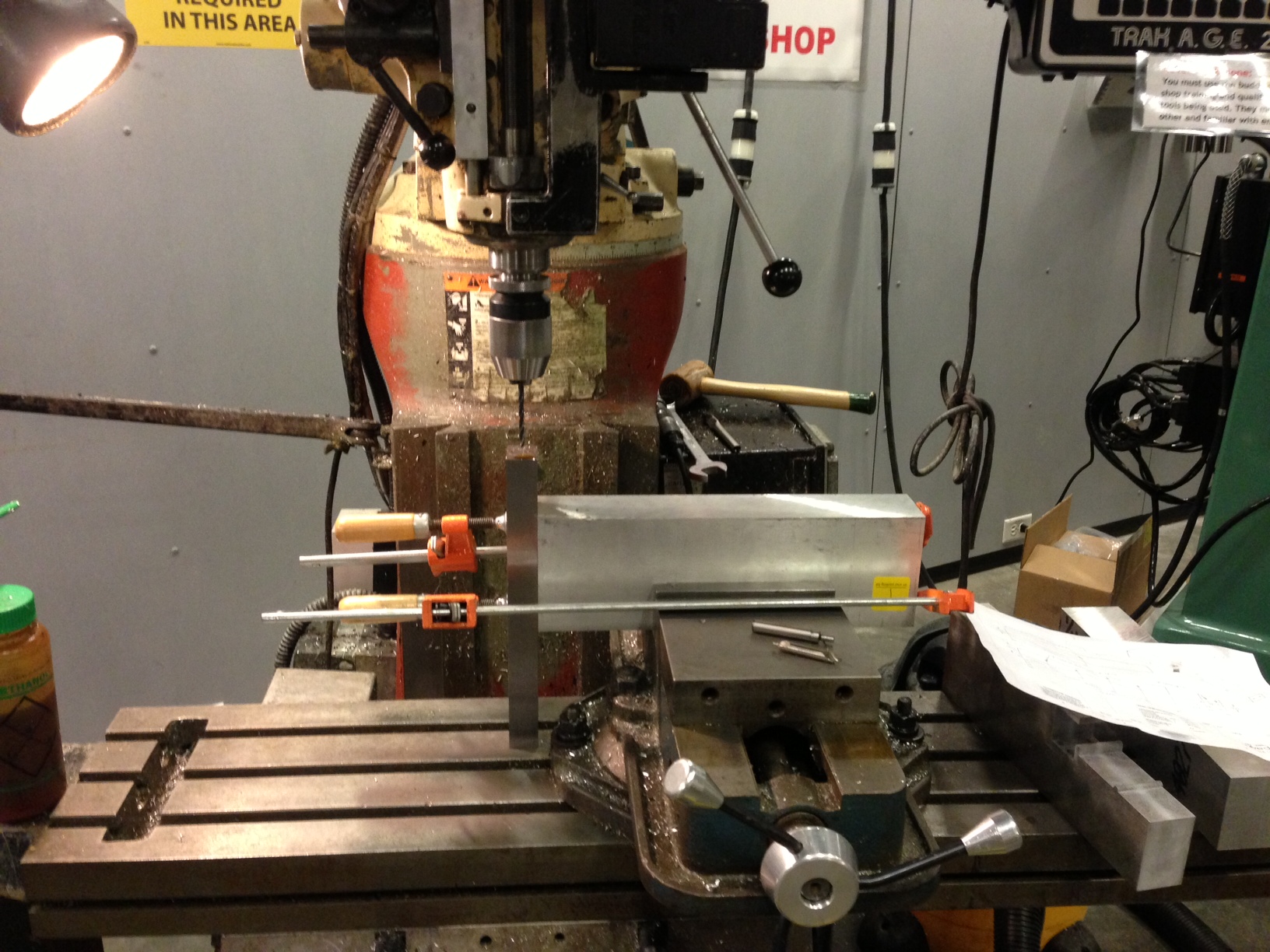
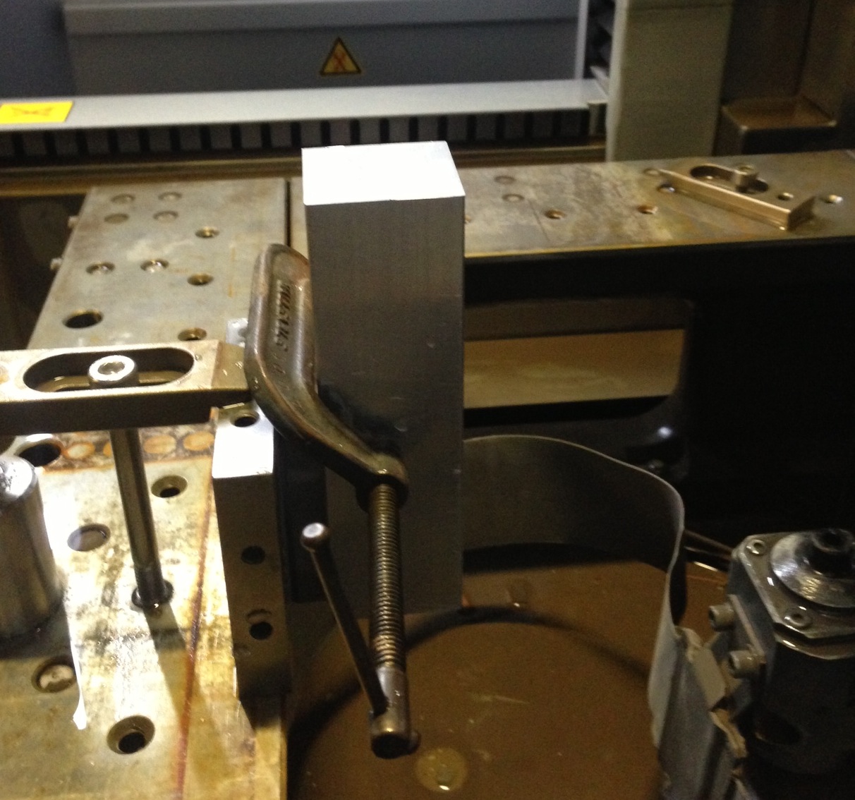
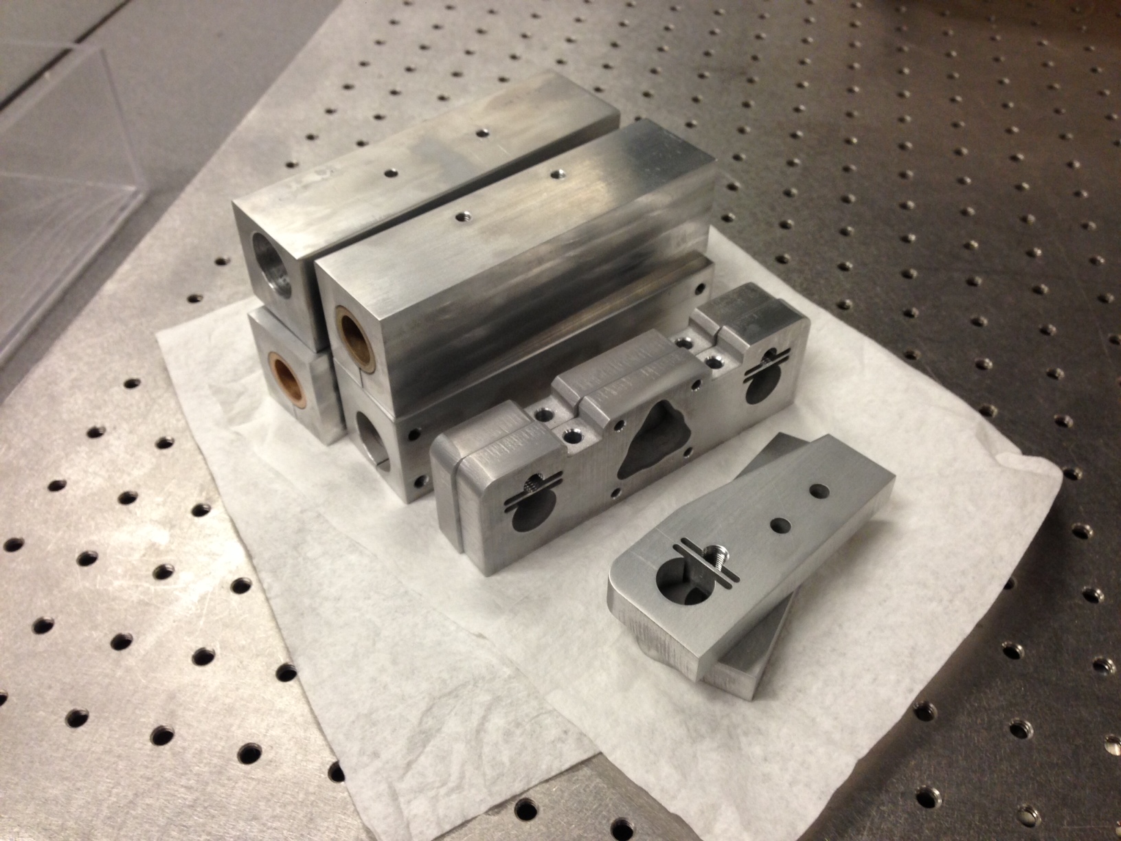
The hardest part to fabricate was the bearing blocks which hold the bronze bushings used to constrain the x and y degrees of freedom. My original plan was to just drill them out on the Bridgeport but soon realized that a drill of that length (5.25") would be hard to come by. Instead, I resorted to the machine that inspired this whole project: the EDM! I simply mounted the blocks vertically in the machine and cut out the hole. This is now the current record of tallest cut in our EDM.
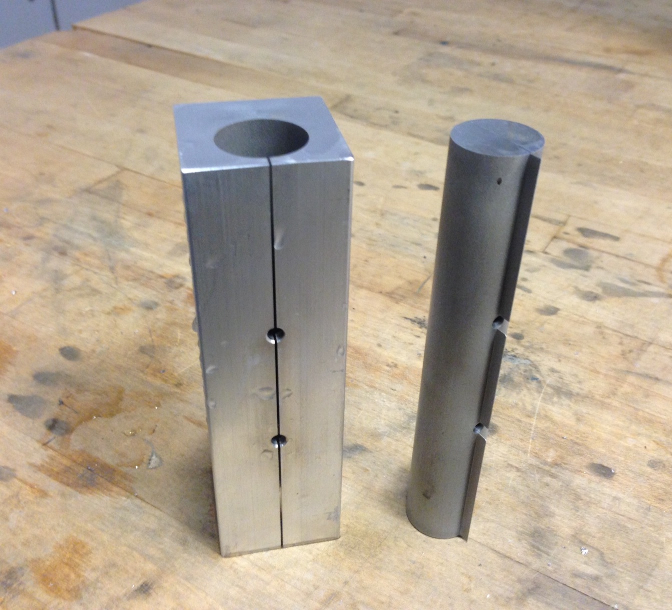
They came out perfectly and make for some of the smoothest linear motion I've ever made.
Here's how the fabrication progressed over the course of a few days:
Here's where things got a little trickier.
An EDM works by creating a spark between the wire and the workpiece. To generate this spark I want to make a circuit that charges a capacitor bank and then offloads that charge into the gap between the wire and workpiece. My circuit went through a number of interations
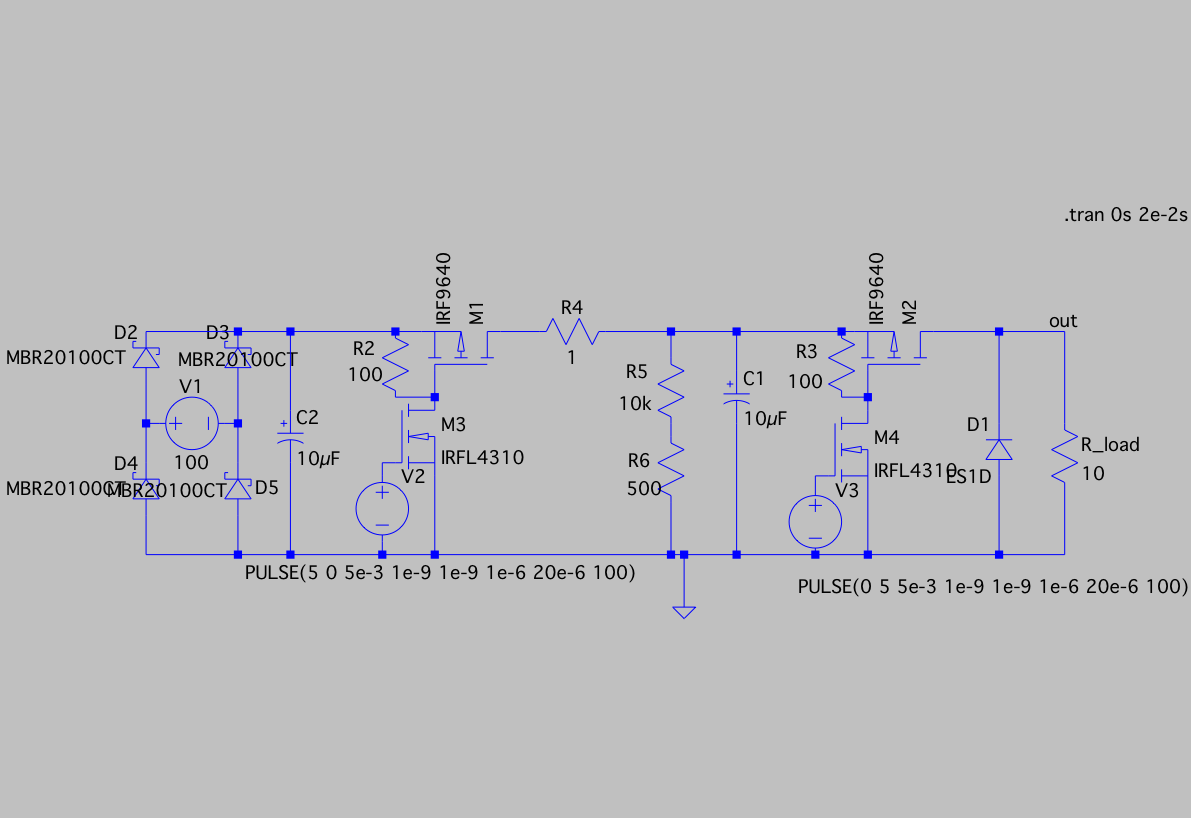
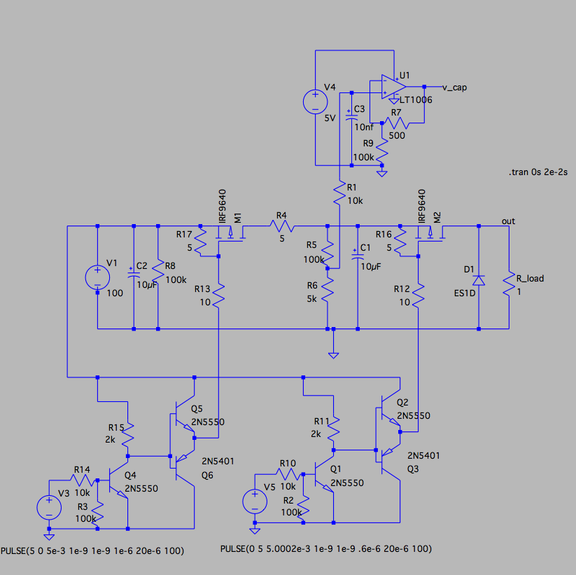
and ultimately looked something like this...
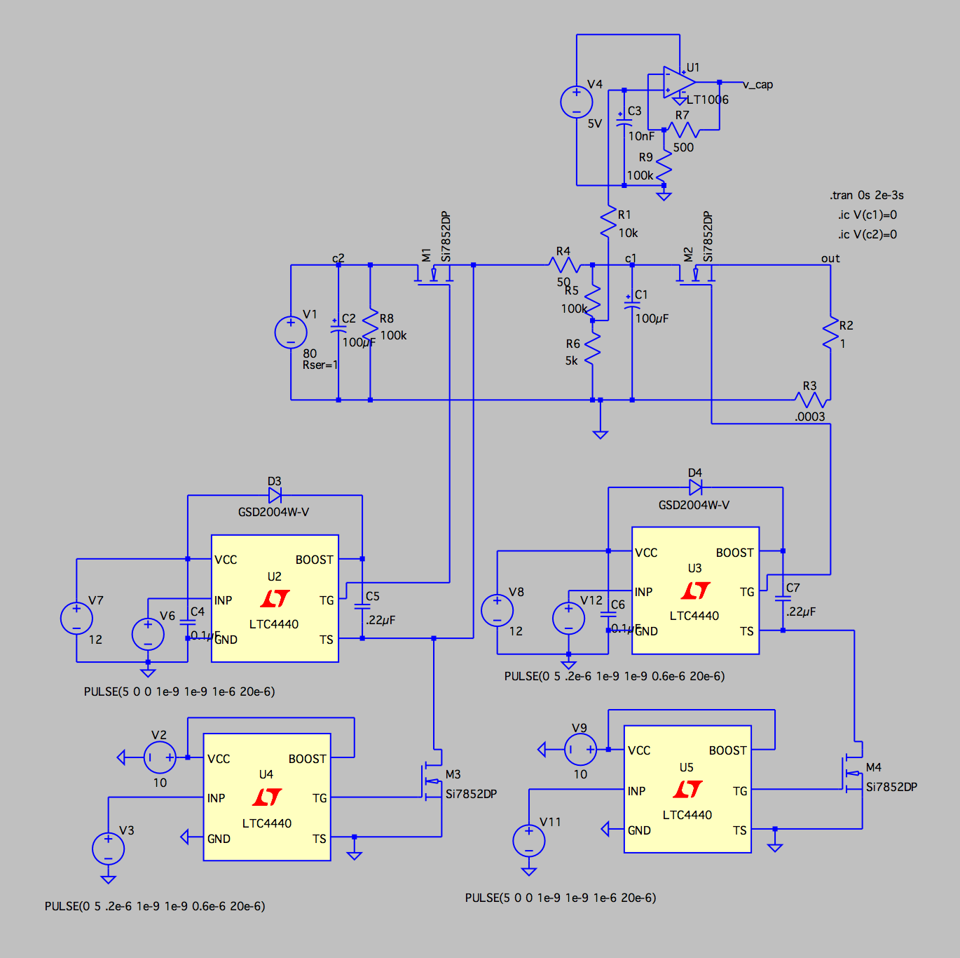
Here, high-side N-channel MOSFETs are being used to switch between charging and discharging the capacitor. Each high-side MOSFET has a high-side gate driver and a low-side gate driver. The high-side gate driver uses a bootstrap circuit (formed from the diode and capacitor) to generate a voltage higher than the supply rail. Because of this, the low-side driver was needed for this to function properly.
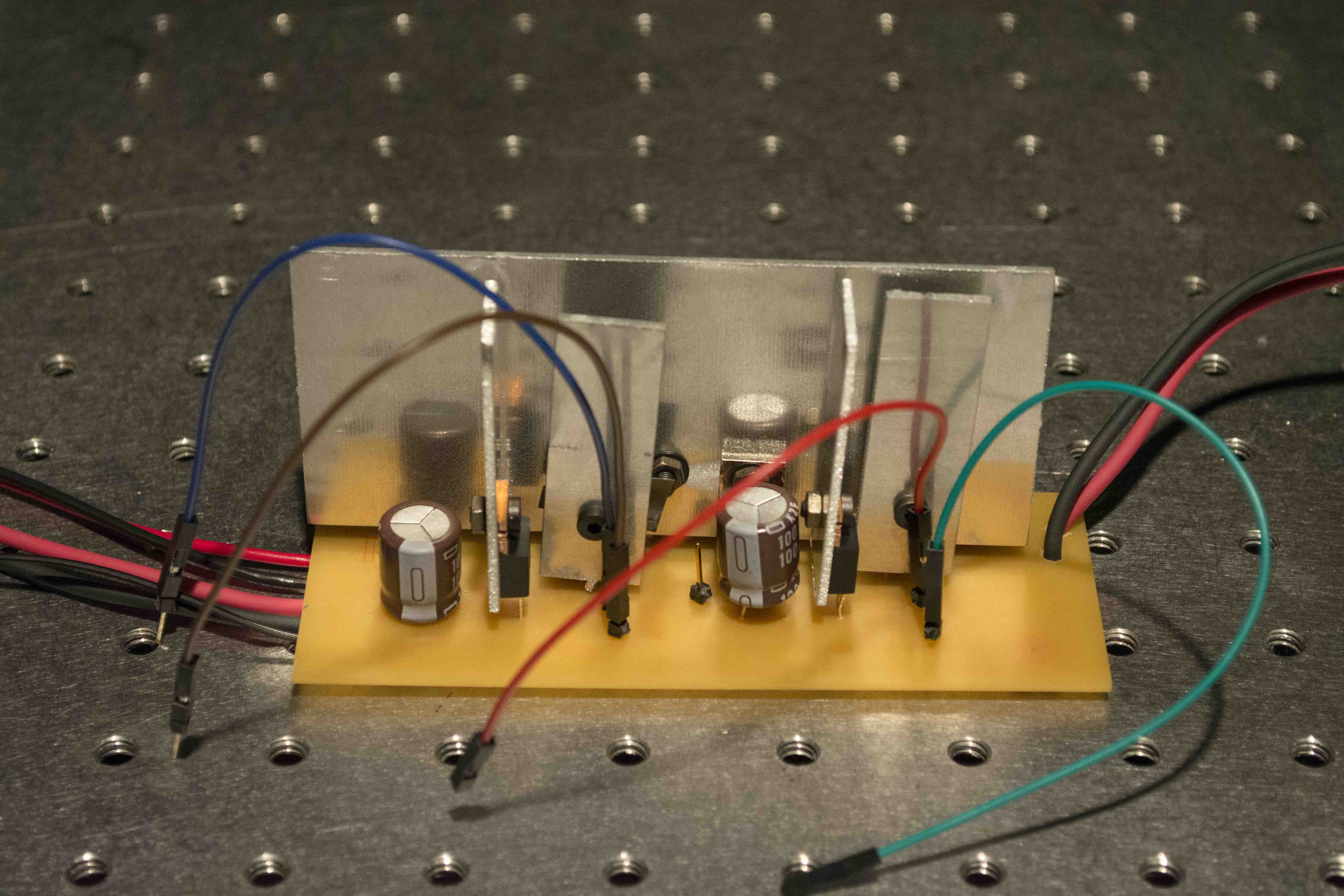
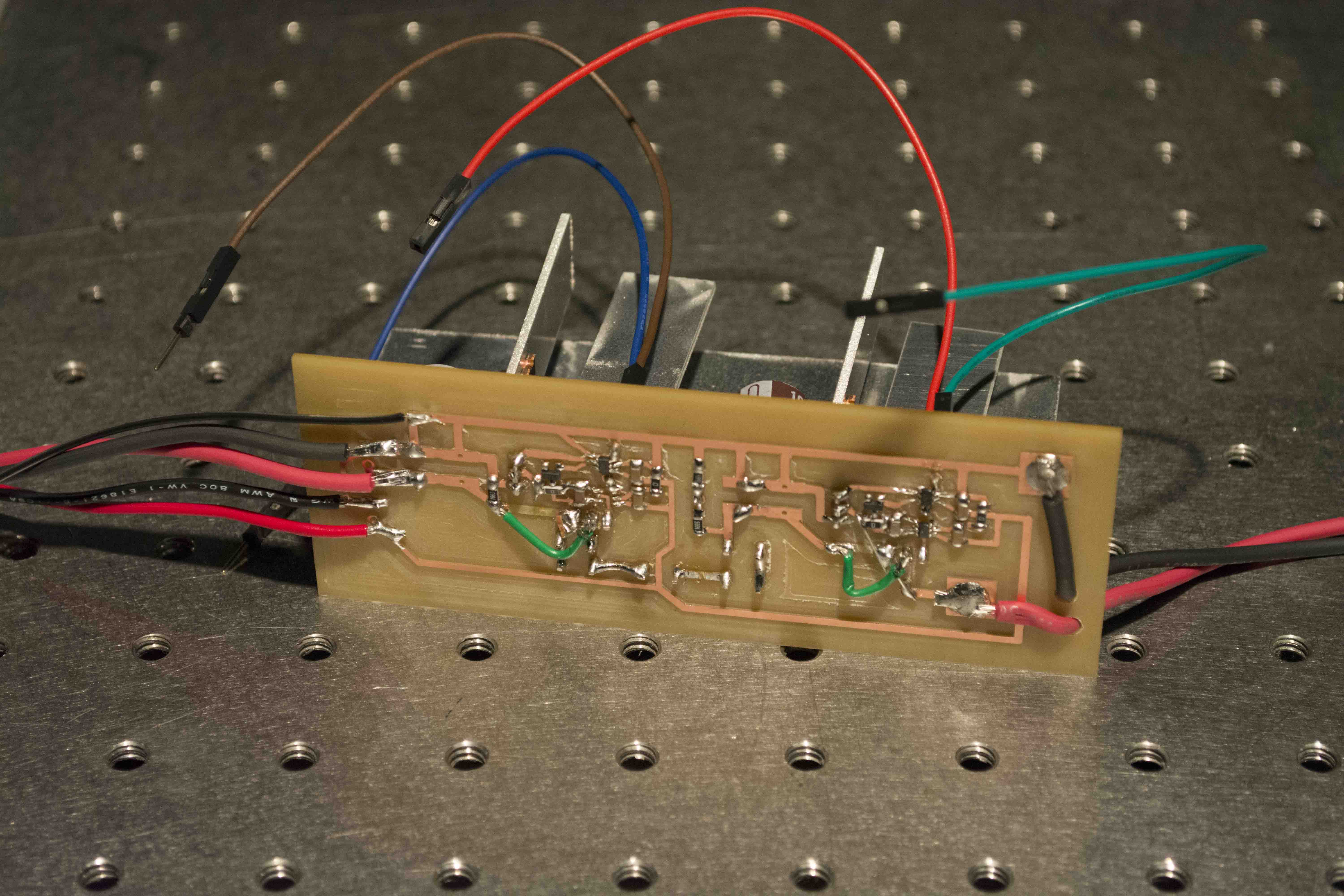
The physical realization of the circuit invovled lots of heatsinking to ensure the MOSFET's and resistors don't overheat.
After my previous success with a low-voltage implementation of a similar circuit, I was hoping to have success here. Unfortunately, it seems parts like gate drivers are quite fragile. In my early testing I seem to have quietly fried my gate drivers such that they no longer bootstrap and are unable to switch my high-side FETs. In the gate driver's defense, I probably made a pretty egregious error of initially testing the board while some of the FETs were mirrored such that their source and drain were swapped. After many hours of debugging and running out of gate drivers, I had to call it for this circuit.
Having spent most of my time worrying about the fabrication and power electronics of this machine, the controls have thus far been a little neglected.
The wire feed mechansim is working and is controlled by a dedicated A-Star microcontroller running a PID position control loop.
As a temporary means of control for the X and Y, I'm using a TinyG. The machine moves very nicely.