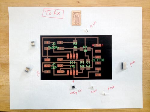
As I am still fairly new to embedded programming, I made the step response transmitted and receiver sensor from Neil's example to practice making a PCB and programming.
HOW TO MAKE A TOUCH SENSITIVE COLOUR WHEEL
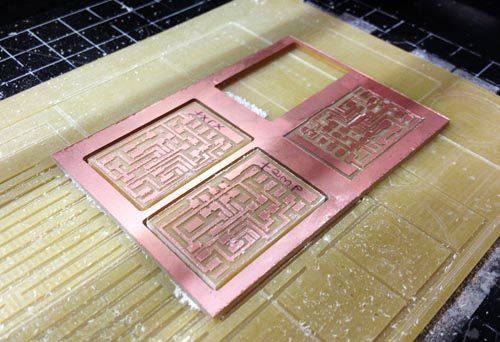
1: MILL AND STUFF YOUR BOARD
The milling process seems pretty straight forward now:
Stick board to base plate (make sure it lies flat and doesn't move too much when you press it - this happened to me the first try and the traces were cut through because the end mill seemed to bounce about as the board moved up and down!)
Open make_png_rml in terminal
Set settings to 1/64
Make path
Set the origin of the end mill by moving to the correct point on the board
Check the mill is touching the surface at several points across the cutting area
Make rml
Send it!
Repeat for the 1/32" end mill
2: DOWNLOAD AND INSTALL PYSERIAL AND THE CODE FILES
Kelly and Shahar's pages were very helpful in understanding how to install everything you need to make your circuit board work: AVR software, FTDI drivers, install PySerial etc
Connect the TxRx board to your FabISP with the ribbon cable, and the USB and FTDI cables
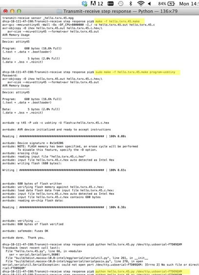
Open Terminal and write:
"make -f hello.txrx.45.make" - this executes the make file which turns the c code file into hex
"sudo make -f hello.txrx.45.make program-usbtiny" - this sends the hex file to the FabISP to program the TxRx circuit board
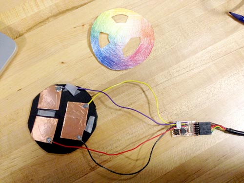
You can disconnect your ISP now and connect your copper pads - I used three pads with wire soldered to them and the wires fed though a 2x2 ISP header(the two outer wire connector points should be connected to the Tx and Rx/GND points when you plug it onto the 2x2 header on the TxRx board)
"ls /dev/tty.usb*\" and then Enter - this should give you the ID number for the USB port which your TxRx circuit board is connected to
"python hello.txrx.45.py /dev/tty.usbserial-enter your USB port ID code here" - this runs the python code which visualises the change in resistance when you touch the different pads
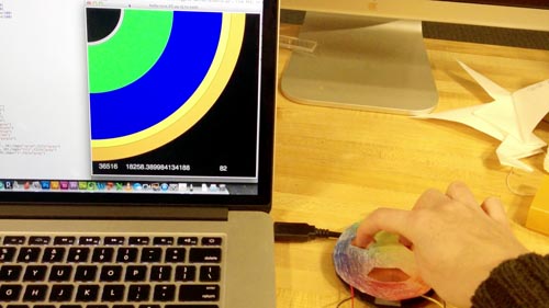
It worked!
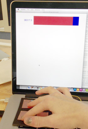
4: PLAY AROUND WITH THE PYTHON CODE TO CREATE DIFFERENT VISUALISATIONS OF YOUR SENSED DATA
Here I played with the visualisation to make touching one or more of the pads could be linked to a colour wheel, i.e. one pad is yellow and the other blue so touching both creates green