project proposal
press fit construction kit
pcb fabrication
3D scanning and printing
electronics design
molding and casting
embedded programming
cnc machining
| [08] ~ COMPUTER-CONTROLLED MACHINING |
|
This week we had to make something big.... I set out to make a reconfigurable-foldable piece of furniture. The idea is that the surface of the furniture is comprised of many slats connected by joints that can make any angle. This would allow the surface to approximate the curvature of any continuous line drawing. I quickly narrowed the scope of my joints from being able to make "any angle" to being able to make angles in 45 degree increments. However, after playing with the 45 degree angles in Solidworks and in the cardboard prototype, I decided I didn't like the forms I was seeing and narrowed even further such that the joints can only form angles at 90 degree increments. 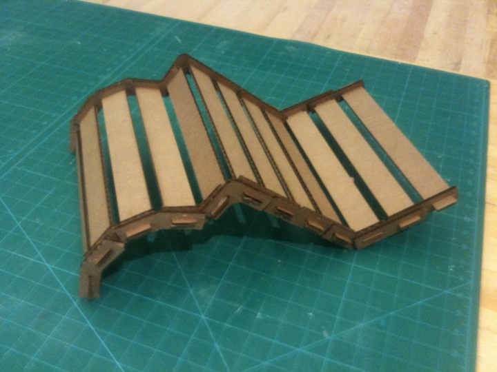
I like the idea of being able to sketch out arbitrary lines on grid paper and being able to replicate that with the surface. Here are some of the possible configurations given 10('ish) slats/joints. 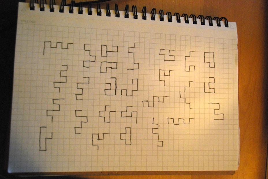
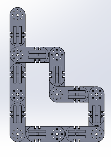
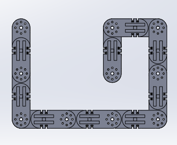
Ideally, most of the surface configurations would actually be able to support load. Since I didn't have time to do a full-scale prototype and test the load capacity I decided to do some rough FEA simulations in Solidworks. 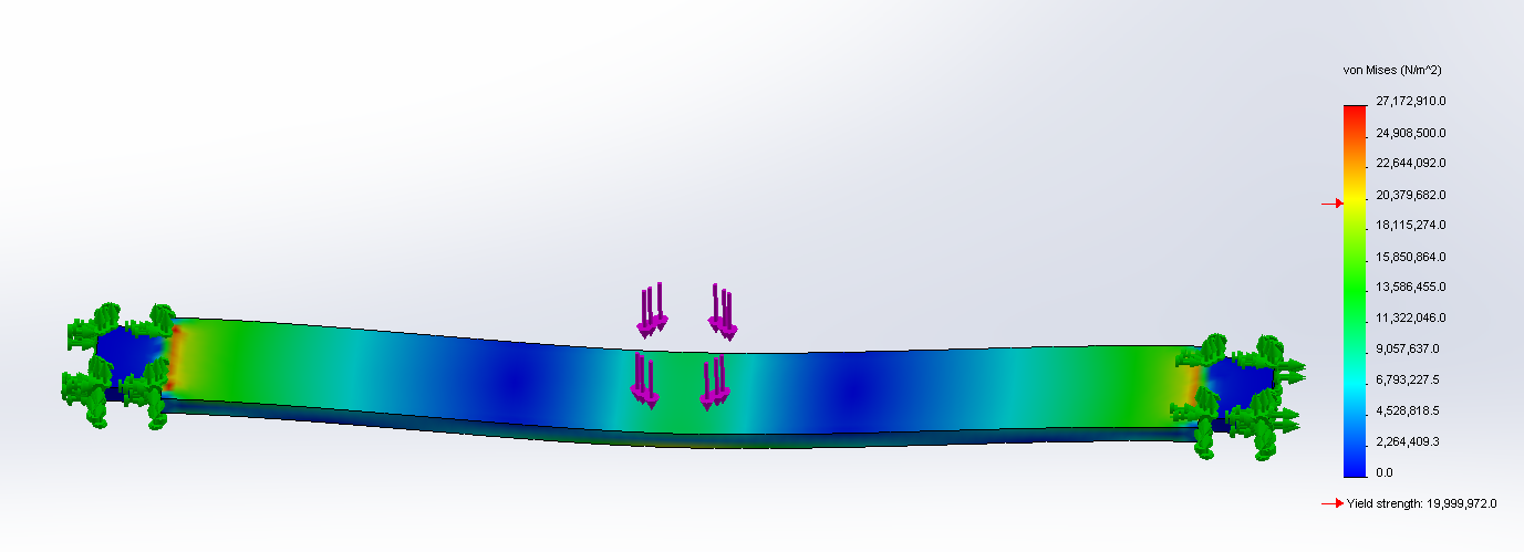
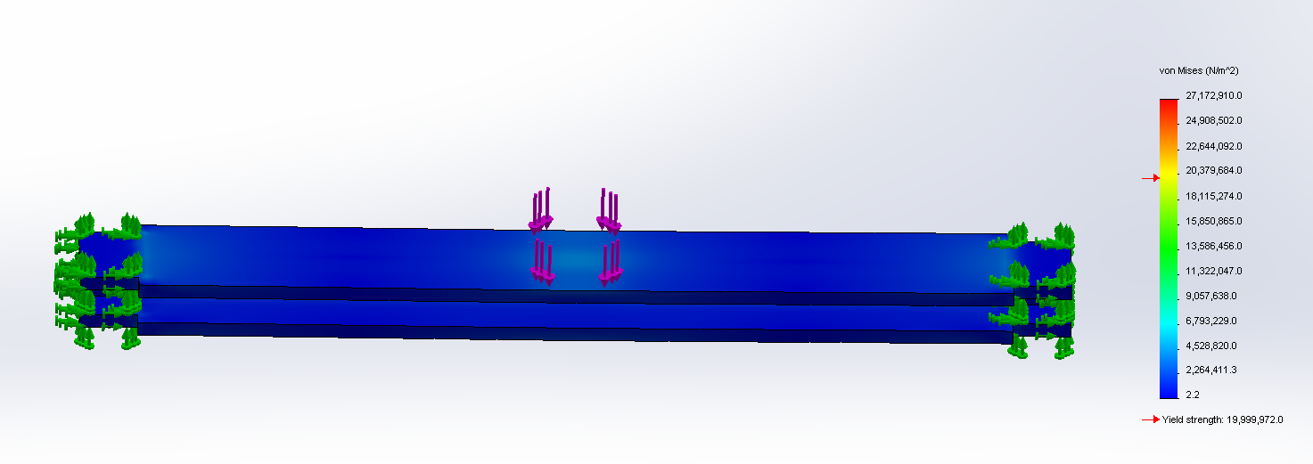
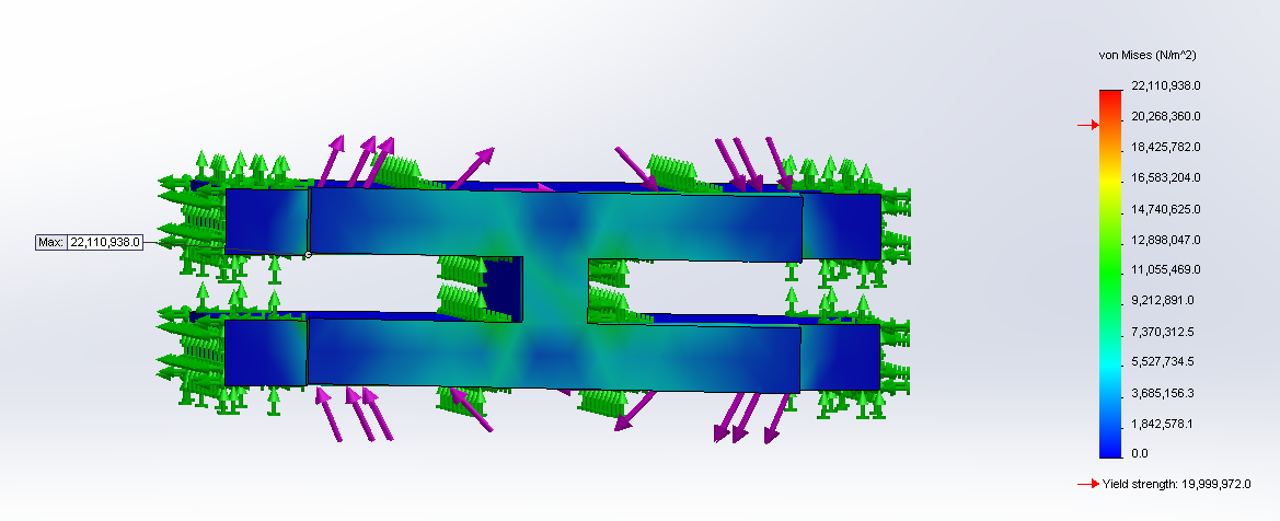
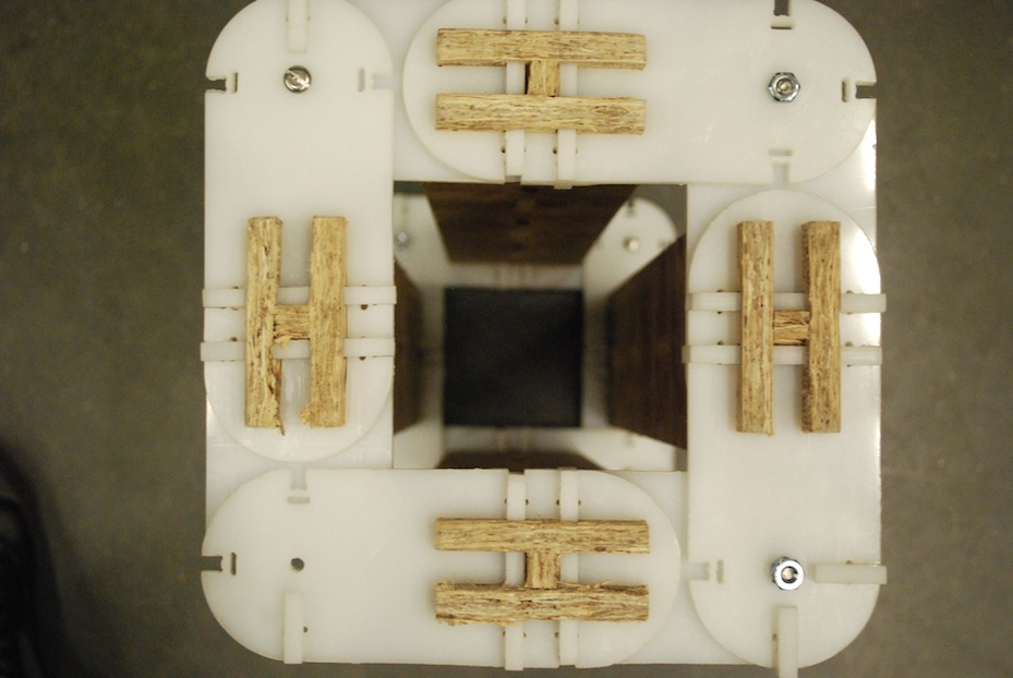
I employed a few engineering tricks to greatly improve the load capacity of the structure. For example, I made the slats into I-beams (albeit, very short ones) to better stand up to bending moments (and centrally located forces). I also used snap-fit sheer pins to connect the two joint pieces to the I-beam. This minimizes the torsional load that the wood sees (I suspect OSB doesn't like torsion) and converts it into a compressive load on the HDPE (much better). 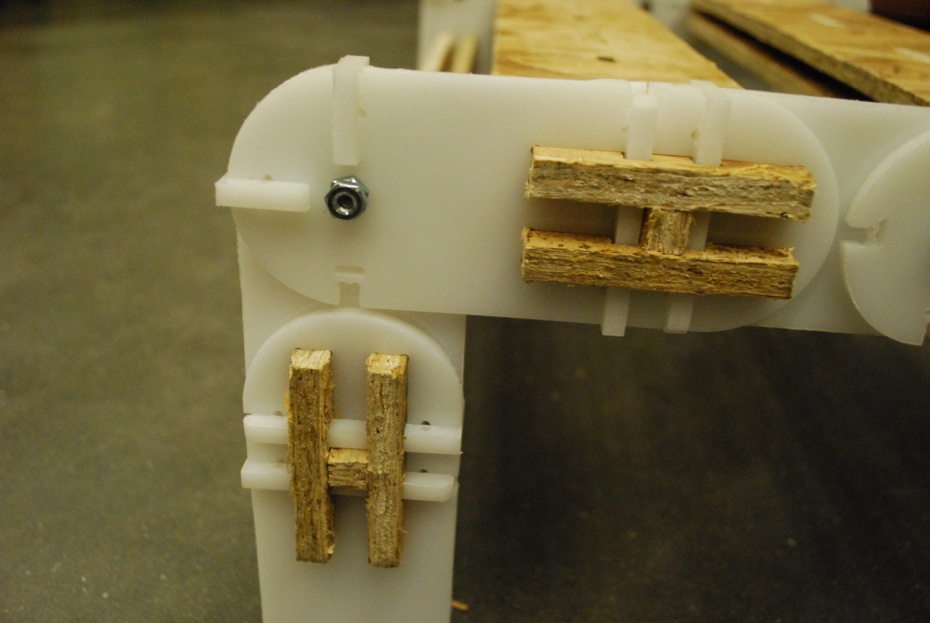 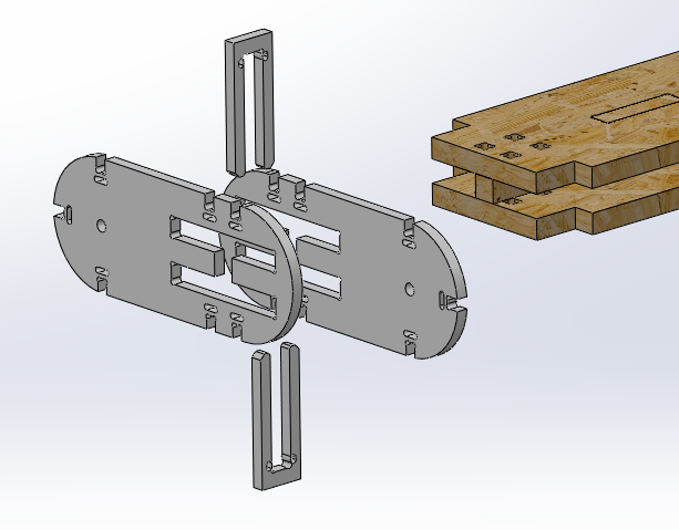
Ideally I would've made the slats out of a stronger wood and the joints out of a stronger or thicker material (like 1/4" aluminum or 1/2" HDPE) instead of the OSB and 1/4" HDPE, respectively, that I had on hand. I cut the wood pieces on the Shopbot and the HDPE on the waterjet. I layed out my pieces and fit just about as many slats on the 4'x8' sheet of plywood as I could. My trick for laying out pieces on the Shopbot is to leave a space between parts that is 3 times the diameter of the tool. This leaves a central spar that remains intact between the pieces that you can use to keep parts attached (using tabs). 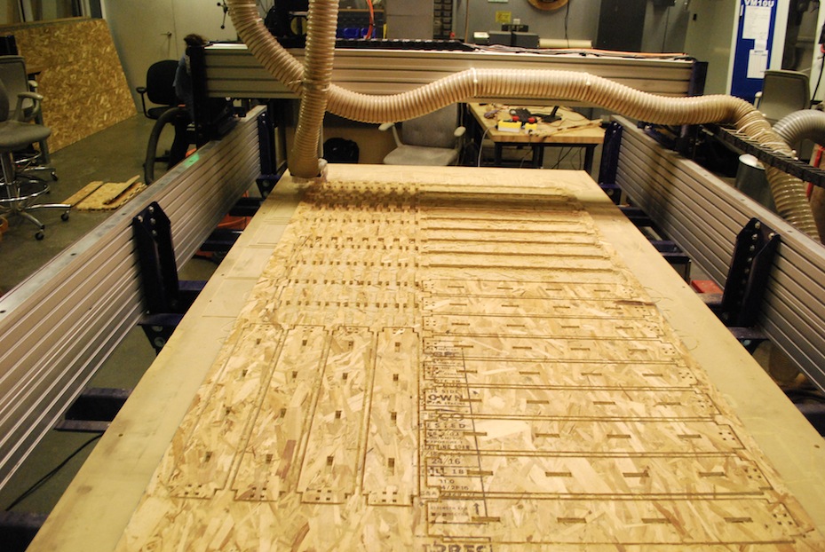 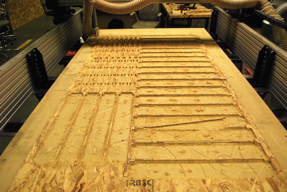
Here are the settings I used on the Shopbot: Job 1: Small-Holes Tool: 1/8" end-mill Pass-depth: 0.125" Feed Rate: 160 inch/min Plunge Rate: 60 inch/min Spindle speed: 10,000 RPM Time: 30 mins Job 2: Cut-out Tool: 1/4" end-mill Pass-depth: 0.25" Feed Rate: 160 inch/min Plunge Rate: 60 inch/min Spindle speed: 10,000 RPM Time: 1 hrAlthough I had designed the joints to be cut on the shopbot, I ended up using the waterjet because (1) the Shopbot was super busy because of the hurricane and (2) I've never used the waterjet and thought it would be fun to try. I was impressed with how easy the waterjet was to use. The trick that initially stumped me in creating toolpaths was to increase the "quality" of the lines (to at least 3). Then you can use the auto lead-in/out calculator and the path tool to calculate the toolpath. On the hardware side, you just want to make sure the abrasive doesn't run out and that you're material is clamped down nice and strong. 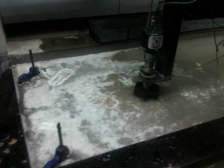
One thing that I learned is that for small'ish parts it makes sense to leave tabs so that the part remains attached to the stock until it's all over and you can use a chisel or knife to take out the pieces. Otherwise, the pieces end up floating around in the water (in the case of HDPE) or worse, end up sinking to the bottom of the pool (any kind of metal). The surface finish on the parts was decent but not nearly as good as milling would be. One odd thing that I wasn't able to figure out was that the small-feature-size flexures were uniformly broken on the second batch of parts I made on the waterjet. The first batch came out fine (left) but the second batch (which I ran a few hours later) have a poorer surface finish and the thin-features are broken (right). 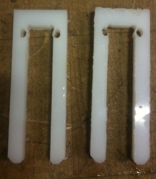
I made enough joints and wood-slats to make 10 surface sections. Unfortunately the wood was a bit of snug fit in the plastic and it took quite a bit of time and effort to make each one. So... I currently have 4 sections with the possible addition of 6 more in the near future. Once I made 3 sections I immediately began playing with shapes and stress-testing the beams. The beams and joints do hold up to my weight (just barely): 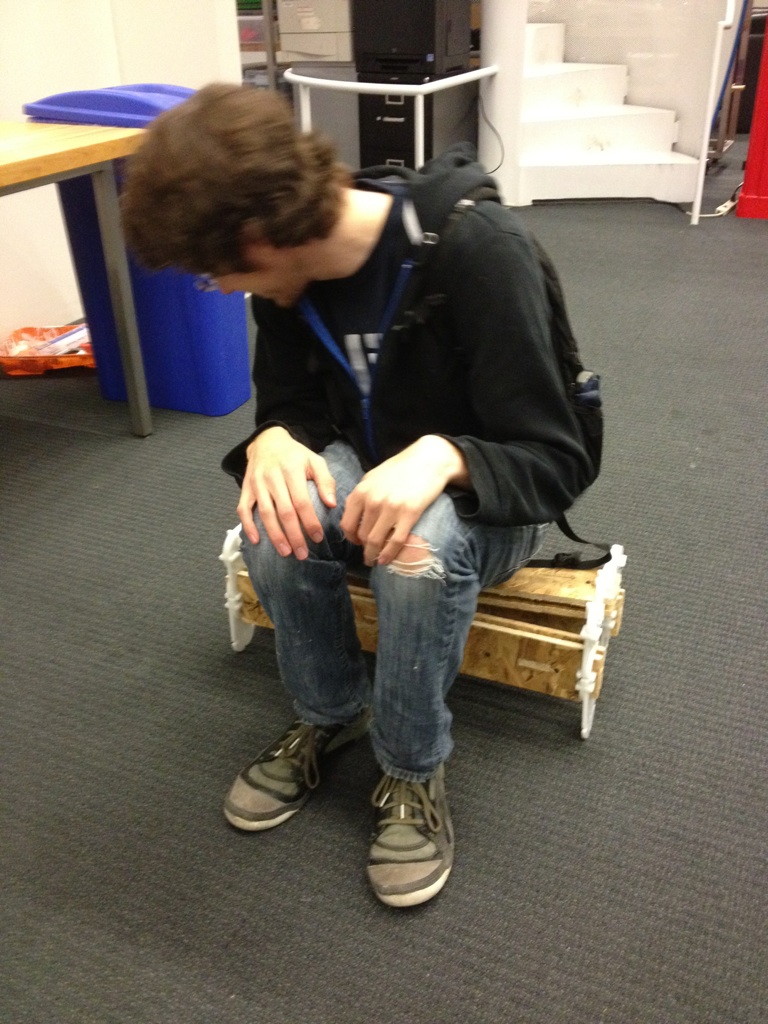 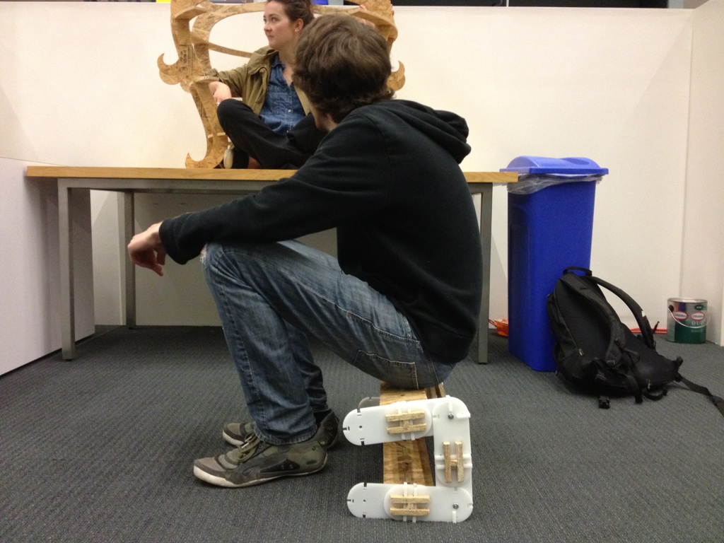
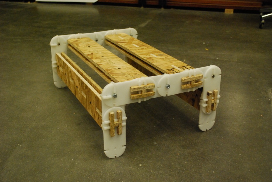
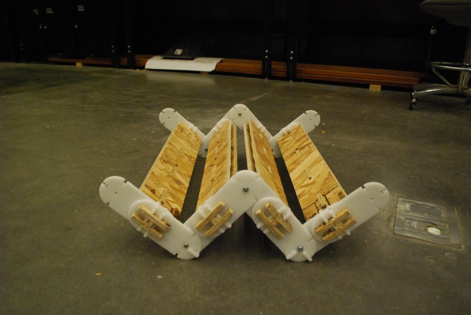
Four segments is nice because it allows you to fold it up into a square pillar. You can then fold it out into a table or some-sort-of zig-zag shape. 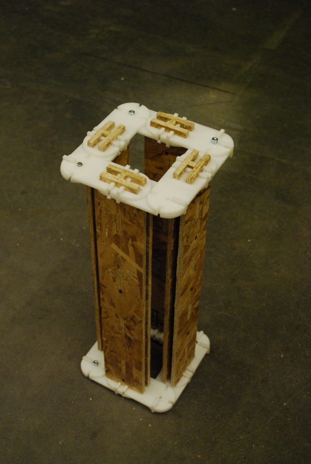
|