010: Input Devices
This week, our assignment is to design a microcontroller board with a sensor and read
what it is sensing. I have made a Hall Effect sensor!
Software:
Eagle (check out my documentation
from a previous week to see how I used it.)
Adobe Photoshop
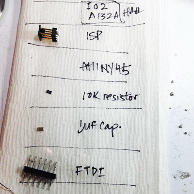
Other materials:
FTDI cable
FabISP
Ribbon cable
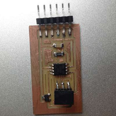
Your new, super awesome sensor PCB
hello.mag.45.c
hello.mag.45.make
hello.mag.45.py
SparkFun Sensor library
Procedure:
Board Design
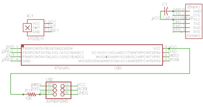
- All the components necessary for a Hall Effect Sensor can be found in the Fab library,
with the exception of the Hall sensor, which I downloaded from SparkFun. Below is the schematic I drew in Eagle.
It's probably a good idea to run the Electrical Rule Check (ERC) tool to verify that all desired components are connected. My
schematic was laid out exactly as Neil's had been (the reason is that I am quite a n--b at this stuff and am playing it safe; I'll
venture a little farther from the nest when my aviation muscles are better developed).
- After trying to route everything as it was done in Neil's example, I discovered that I simply did not
have enough room for one of the wires.
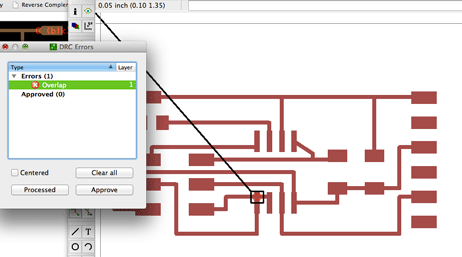
- I remedied this by tweaking the wire width option that is displayed when the routing tool is in use.
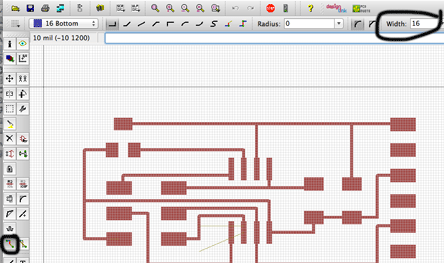
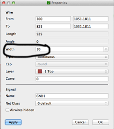
The problem is that changing this after the fact does not modify all your routes' widths. I have not yet found a way to
do this in one shot, but to modify a wire, select the Info  tool, move your cursor over a line, and double click. A popup window opens, and you should be able to manually modify the width of the selected wire.
That modification gave me sufficient room to route the last wire, and my board is complete.
- Exporting the board as an image caused me some trouble -- I forgot that my settings are NOT saved from previous Eagle uses, and
ended up milling boards with poor traces.
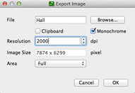
Here are some settings for future reference. The monochrome setting creates the black-and-white board you want,
but with your traces black, which you DON'T want.
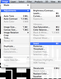
- I used Adobe Photoshop to invert my board image file.
- The milling process is done exactly as in previous weeks (I stick with the default settings). Again, I deburred obsessively to prevent any shortcircuiting.
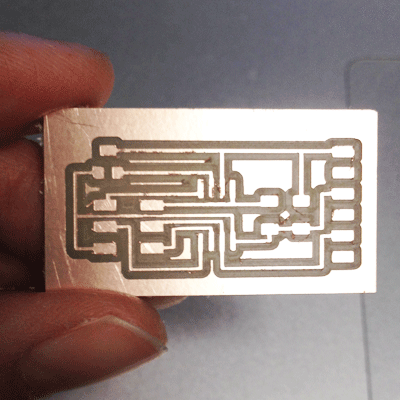
- Soldering was also done as we had done previously.
Programming
Firstly, I am still learning how to do this properly, but I needed a boatload of help! (Thanks, Charles!!)
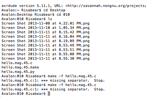
- In my Terminal, I changed my directory to the folder containing Neil's Make files.
- I ran the make files by inputting make -f hello.mag.45.c Unfortunately, I got this error:
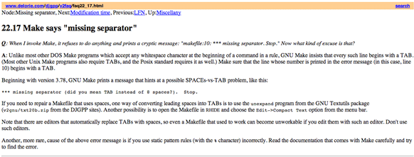
- Like, what the h*ll. (Joking.) I looked up the error and learned that a missing separator
usually results from using spaces instead of tabs in the code:
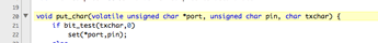
- I went ahead and replaced all spaces with tabs, but still ended up with a glitch in line 20, which
still looks errorless to me:
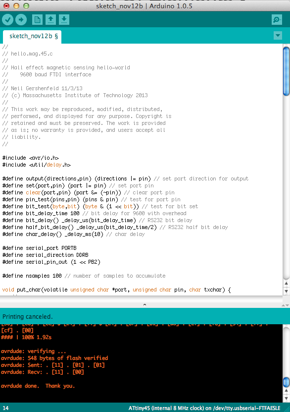
- Instead of fiddling with the code for another five hours, I ran the same make file in Arduino, after which, the
program miraculously worked:
- I went back to my Mac Terminal and opened the python file (python hello.mag.45.py /dev/tty.usbserial-FTFAESLE)
- Success!
2013-11-12 22.04.07 from Lisa N on Vimeo.