Project 09
Input Devices
With the final project on my mind, it seems like it is time to buckle down my understanding of embedded programming and working with sensors in their most rudimentary of states. It is clear to me that an accelerometer is the clear choice for size and simplicity in sensing orientation, but it can’t hurt to try out a few different roads along the way. Note, there are 2D accelerometers as well as 3D accelerometers. Note that a 2D accelerometer is enough to tell me 4 sides with certainty and the other 2 sides with 50% accuracy… a guess :). Since the components I plan to use for my final project are smaller and perhaps more robust, I will work with them soon, but this week, focus on supplied sensors and get familiar with the code.
I started with a list of possible ways to sense the dice orientation
- mercury switch
- capacitance (load or txrx)
- absence of light
- 2D accelerometer + button
- 3D accelerometer
Board Design
Starting with Neil’s load example, I extended this to have 6 inputs instead of just one. This requires a larger chip than the ATtiny45, so it will be some good practice for updating the code and getting the configurations just right.
Testing Neil’s accelerometer board w/ Serial. Note: A hall effect sensor is not a mosfet, just because they both have 3 pins that look alike, they are NOT the same thing. Yes, I did make this mistake, trusting that a part is the correct part because it looks like the correct part is not a methodology for electronics. Round peg in round hole is not enough. Is that enough on this point? I think so, moving on.

Board Construction
This is by far the easiest part for me now, as I have milled quite a few boards. I am happy to say that “rtscts” as a protocol is completely memorized, “ready to send, clear to send.” Without this, boards look funny, and the mill looks broken.
Board Programming
FUSES!!! – oh man, so think twice before setting fuses on a board. If you set the fuses incorrectly, it is not always trivial how to get the board back to programmable. Palash sent me to a wonderful resource for determining the fuses that you want to set for any particular board and configuration. Note: the checkboxes are 0 (LOW) and not checked is 1 (HIGH).
ADMUX — Different on different chips and can be set differently depending on your input pins and the gain necessary. There is a handy table in the datasheet that explains exactly how the register should be setup(this will be 8 bits).
BitShifting 0 (zeros). Looking through Neil’s code, it isn’t quite obvious at first what is what, but over time pieces can be broken down and then I come to find what is actually commented directly next to the code (it just isn’t so clear unless you already know what the heck is going on). For example, setting the ADMUX for inputs and the correct gain includes values the have bitshifted zeros. The reason for these bitshifted zeros is to be explicit. They aren’t necessary, but they do make the settings even clearer.
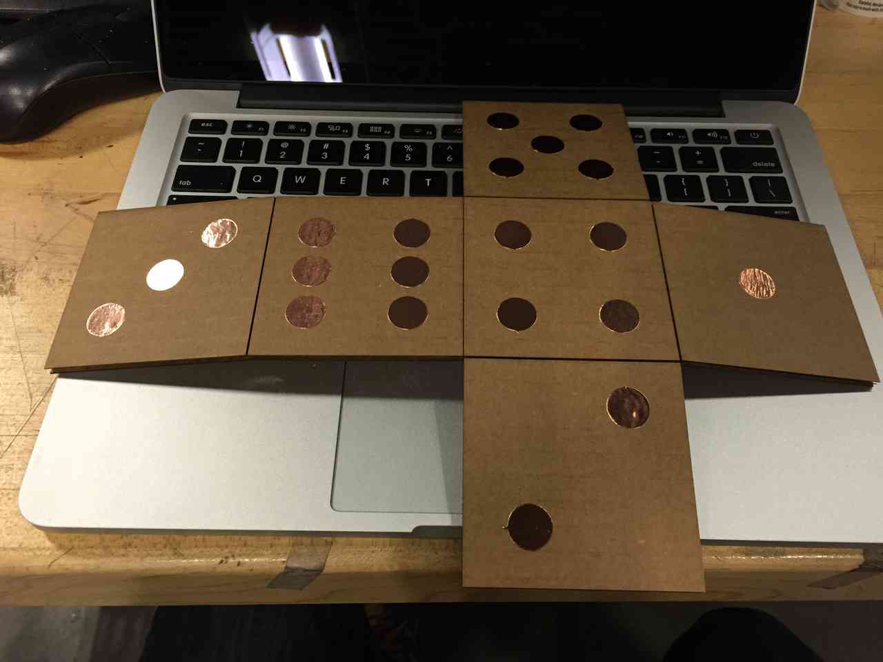
Dice Experiments
Figured I would try using the load sensing on 6 circular copper plates to see if I can tell which side of the die is facing down. The following is the simple process of creating a cube with “vias” for wiring.


Circuit Stickers
It seems like it could use a shout out here since thanks to Jie, I got a chance to play with Circuit Stickers for the first time this week. There is clearly some great potential for prototyping with these stickers, especially since there is a sticker with a programmable ATtiny85! It looks like the one I have is broken out specifically for touch sensing, but I will play around with it soon to see just how useful this could be. If you are working on a wearable project or something in the craft space, this is definitely a great reference, but I am sure there are a dozen other great uses for these sticker circuits.
ModyMyFABISP
While programming boards, I needed to give power to a board that I didn’t have an external power source on, so I decided to add a little switch to my FabISP to make it hot-switchable between powered and not powered programming. It is also nice to be able to give a board power over ISP when not programming, given you might need to power the board quickly for testing. To make this possible, I simply cut one of the legs off of a 2 way switch, and then connected the remaining 2 legs to where my jumper once resided.

ModMyFTDI
The FTDI cable that I purchased was quite long, and really I thought it would be nice if I could have a short one for easy of carrying around everywhere and keeping in my electronics box. Feeling unproductive with my other tasks, I decided to cut the cable and solder the wires back together carefully with heat shrink tubing for insulation. Note: cut and place all of your heat shrink tubing before even turning on the soldering iron. I have made this mistake so many times before that this time, I didn’t even hesitate and wanted to share the wisdom with you. This hack included two layers of heat shrink tubing, just to be extra clean and ensure a useful product in the future.

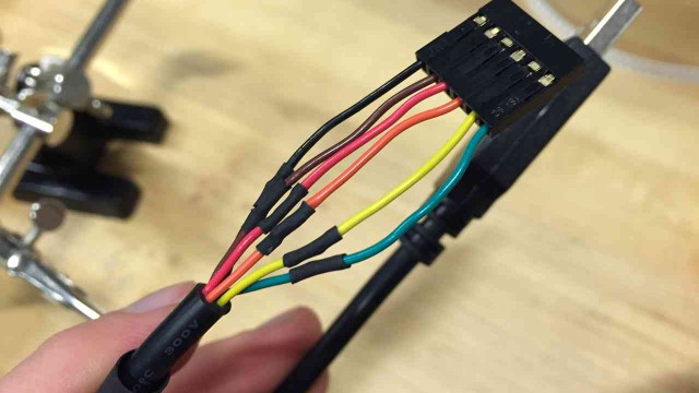

Kind of cute, right? Of course once I made this modification, I thought of all of the times I would need this cable to be nice and long (i.e. if it were being used to communicate the orientation of a cube that I would like to hold more that 6 inches away from my computer :/