Project 11
Networking and Communications
This week was focussed on having more than one embedded device talk to another or many other embedded devices. While there are many protocols and options with regard to structured data transmission, I decided it would be nice to make completely self contained nodes that communicate with each other in a simple way, perhaps using light or sound, not necessarily a form of radio or digital communication.
Ever since I was introduced to the concept of Cellular Automata, I have had a continued fascination with emergent behavior and simple simulations for complex systems. About a year ago, I was discussing with my friend, XiaoYang, that I wanted to make Conway’s Game of Life a tangible experience, something that kids and adults could play with on a table or in a room. He too had thought about this experience and wanted it to be as analog as possible, and that resonated with me.
First let me explain Conway’s Game of Life. The intention of Game of Life is to emulate the pattern of life. This is done with 3 simple rules. 1) Life births life 2) No one survives alone 3) Overpopulation creates a lack of resources and so also ends life. It is a simple simulation organized in a pixel grid (originally on a table top board game of Go), where each pixel has 8 neighbors. With every step of time, each pixel will update simultaneously based on its previous surroundings. Conway’s rules are that 2 neighbors …
So you might have noticed a couple of difficulties in creating this physically.
- The tiles all need to update at the same time
- The tiles need to communicate(sense) with their neighbors
- Pixels don’t take of physical space, so 8 neighbors is much easier in virtual space
Let’s tackle each one of these separately.
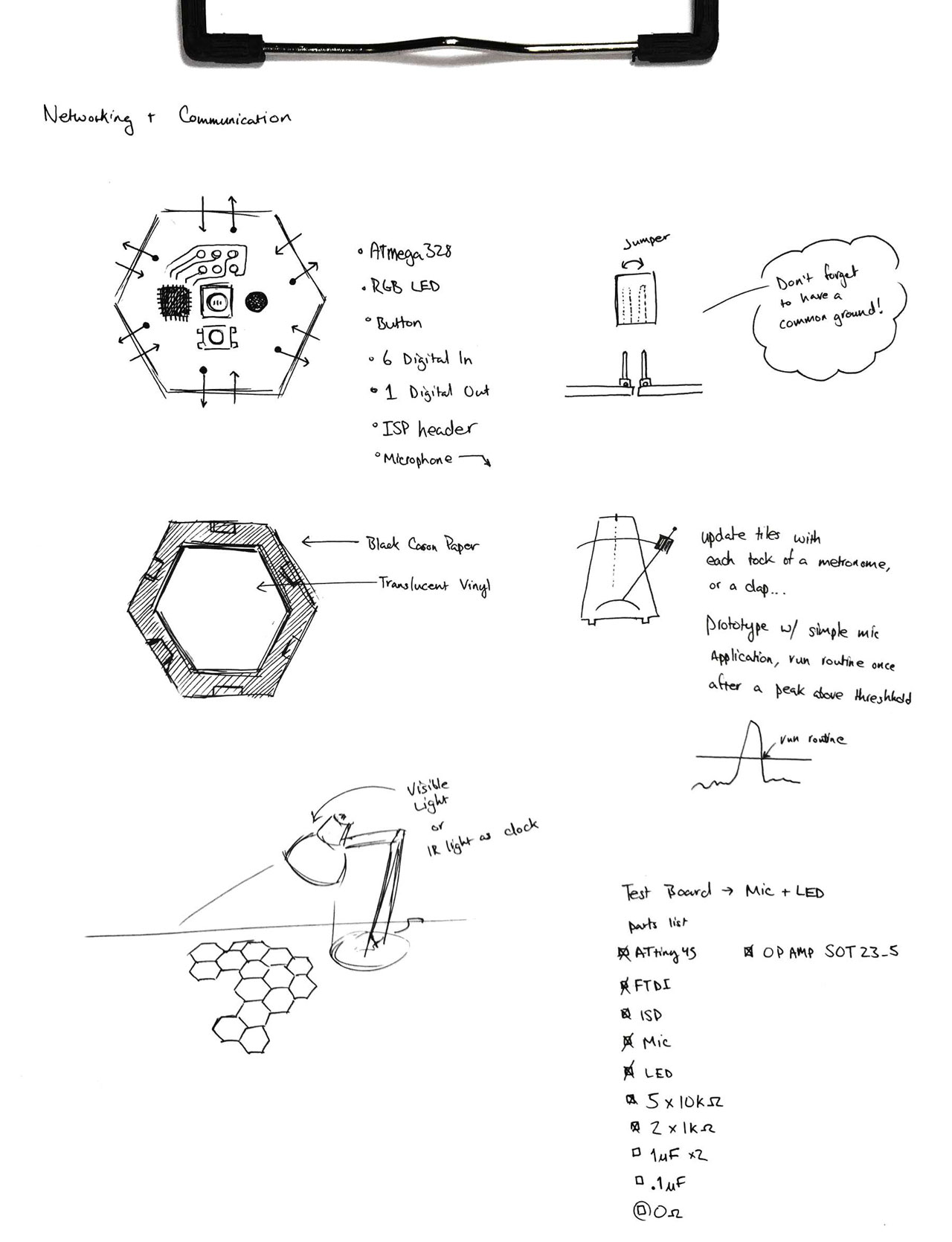
1. To make the tiles update all at the same time, there are many methods that could be used to synchronize the clocks of each of the micro controllers. I particularly liked this one that Palash suggested which relies on a bit of biomimicry to emulate the way Fireflies synchronize their flashing (original link, refined). That would have been cool, but I didn’t do that. What i decided is instead of having a computer be the clock, why not let the user. Using the Electret microphone and the basic fab op-amp, I can sense when someone snaps fingers or claps or sets a metronome on the table to be a regular source of ticking. I am hoping that the user causing each routine or tick will help with the understanding of the system and make it more fun/inclusive in the process.
2. Sensing neighbors! To sense our neighbors, there are again many options. Since I will be signaling the on and off state of a single tile by illuminating it, I would eventually like to have phototransistors on each side and simple sense the state of the neighbor directly. Imagine each phototransistor is protected from sensing its own state and only focused on the neighbor. Another option is some spring loaded pins, a la MagSafe or little bits. (Btw, sides will definitely have magnets either way). And lastly, for prototyping speed, sensing can just be high/low on pin. Even with this method a bit of thinking needs to go into the process. The sides will be mirroring each other and we need to have transmit, receive, and ground. Luckily 3 is easily reversible, so 3 pins at each side will act nicely as a link for communication.
3. Conway liked having 8 neighbors, but unfortunately octagons are not a regularly repeating pattern. Sure, an 8 sided shape can repeat, but for sake of simplicity, I chose the next closest, the highest regular repeating polygon, the hexagon. So instead of this simulation being Conway’s Game of Life, it will be inspired by and have to have a rule set of its own. There is some existing work with the hexagonal version. While the results don’t seem as interesting as the original, maybe the physical version will provide new exploration with the hexagonal game of life.
Sketch
Prototypes
First I needed to figure out how the mic works, so I decided to modify one of Neil’s boards with the Electret mic on it, and add an LED output to simply display noise over a thresholded value. Sparkfun has a nice board just for this kind of thing, but I won’t be using it, just learning from it :).

Milling was a little weak in the corner, but a little x-acto work can fix it. Note: when milling a board, placing your board in a spot that is less often used will yield a more flat cutting surface. So don’t cut in the bottom left corner. If you are in the current class and reading this… carry on cutting in the bottom left corner :)

Not sure if this is much quicker, but it does remove much of the doubt with regard to quality of soldering, and it really makes the board look clean. That said, these boards are not final boards, so I should be doing this as quick and dirty as possible.
Melting the solder paste at 235 degrees Celcius for about 60 seconds (just watch for the joints to become shiny). Careful, the board remains hot for a while (i.e. 5 minutes after being on the hot plate).
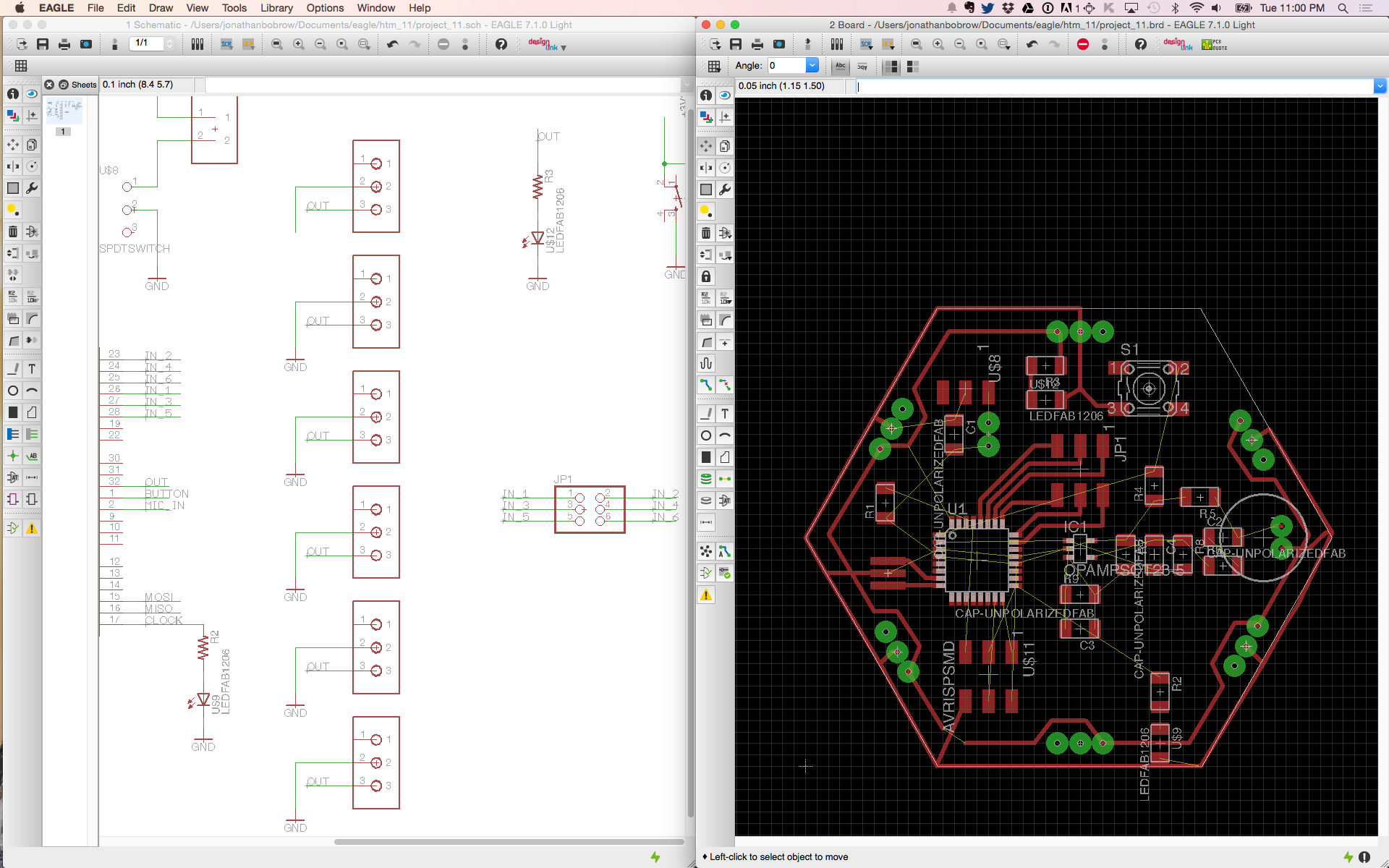
Designing a board
For me, this class could be renamed How to Make (Almost)…
Designing a board takes time, and I consistently underestimate the amount of time with which it will take. I need to remind myself that these are not production boards, but it doesn’t help that this board was going to be a hexagon. My tip to future HTMers is to make the board the quickest way you know how. (i.e. skip the shape here and use it like a breadboard). Anyway, that is not how I proceeded so enjoy my struggle to route this board within 2 inches and on a single side.

Getting the connectors and main components in place.

Making the board a hexagon in eagle is not easy, and there is not a quick way to have traces snap at 60 degrees… (I would love for someone to correct me here)
Got me strategy down and almost there with the board design.
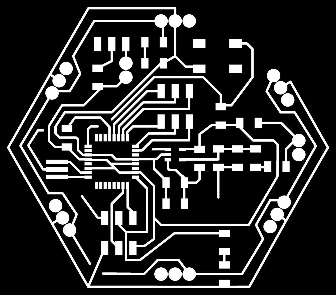
A couple of jumpers still needed but what the heck, let’s mill the board and then solder some wires where needed :)
Programming
The application itself is quite simple. Each node needs to sense 6 sides (6 digital input reads), and display its state (1 digital write), listen for a tick (1 analog in from microphone). Also, to toggle each nodes state, a button is on board. For the final version, the button should be mounted on the bottom so that the whole object clicks down. The order of the 6 sides doesn’t matter, we are simply going to count how many of them are high, and determine our next state.
Software Simulation
To test that the snapping for steps would be fun, I made a quick processing sketch to run Game of Life but using the microphone in my computer.
Communication for Dice
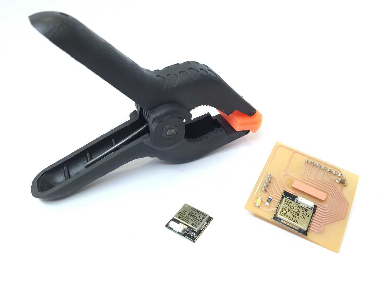
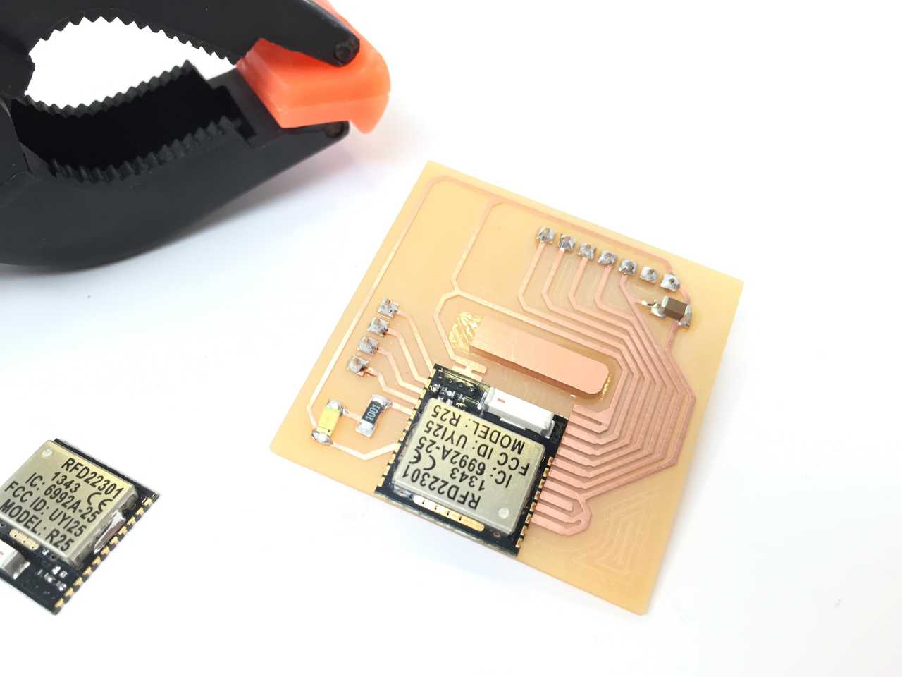
Due to the relatively small size of dice (16mm x 16mm) the PCB inside of the dice is going to have to be fabricated slightly differently than my previous boards. The brain of the dice will be an ARM Cortext M0 w/ a BLE (Bluetooth Low Energy) stack in the form of what is called an RFduino. The footprint of this board is 15mm x 15mm, so I have started the designs for a daughter board, which will surface mount onto the back of the RFduino (which itself is a surface mount part). There will be two versions of the daughter board.
Version 1 will consist of a 9-dof IMU which is show here on a breakout board by Sparkfun. The SMD IC is actually only $12, so it closely mimics Amanda’s IMU within the same price range. This board is internally performing sensor fusion among a 3-axis accelerometer, a 3-axis gyroscope, and 3-axis magnetometer and then delivering that message via I2C.
Version 2 will have the same 9-dof sensor but in addition, it will have 3 H-bridges to control 3 momentum wheels (which are custom modified vibration motors, more on this later).
To program the RFduino without mounting it to a breakout board, I created a programming jig. It matches up with the pins and simply requires the pressure of a clip to maintain contact while programming. The jig also has an LED on pin 6 so I can test that the board is successfully programming. Once programmed, the chip can then have its daughter board soldered in place. I am figuring out if I can extent the programming pins to be accessible through the number 6 on the die.