Final Project Progress Part One
Intro
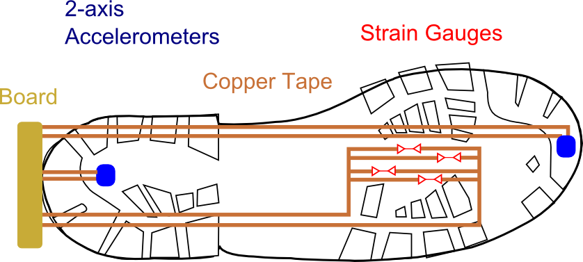
This week is similar to molding and casting in the sense that the work will directly translate to my final project idea. If you remember from my initial project proposal, I want to place an array of sensors on the bottom of a boot to provide proprioceptive feedback to astronauts during extra-vehicular activities. This week, I will focus on accelerometers and strain gauges. The idea is to use flexible copper tape to connect the sensors to a board that is located in the back of the boot. The copper tape will be over cast with the silicone boot created in a previous week.
Hardware
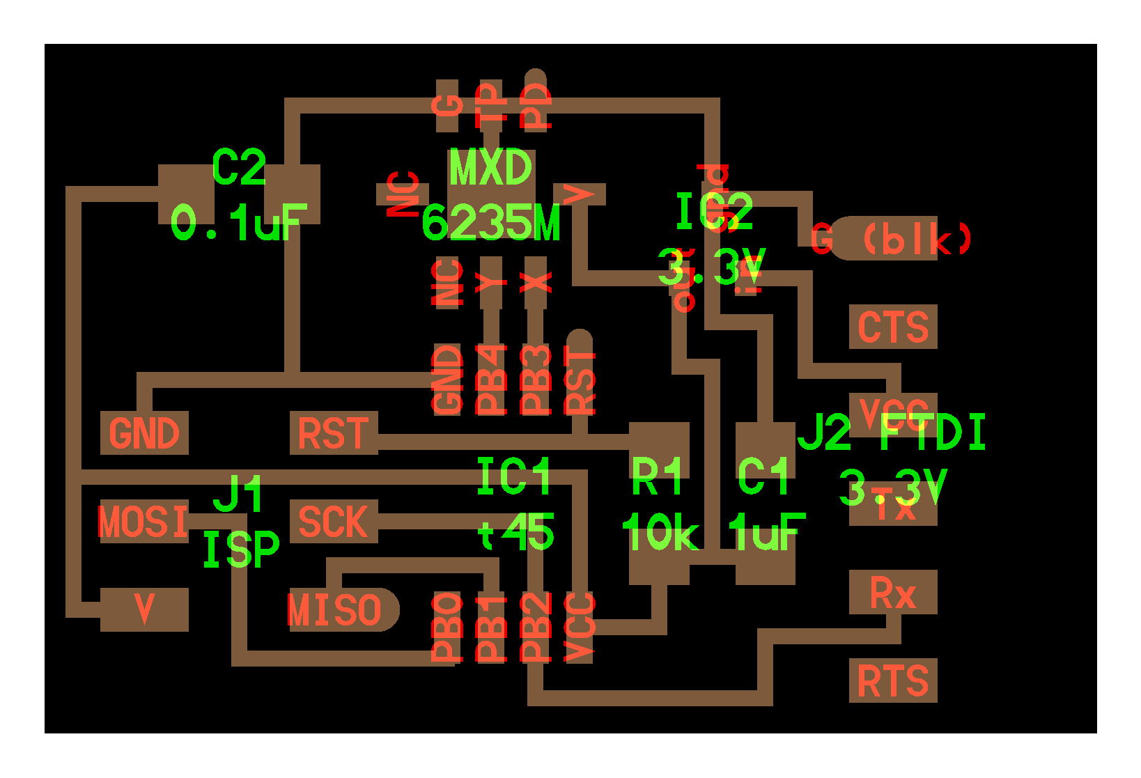
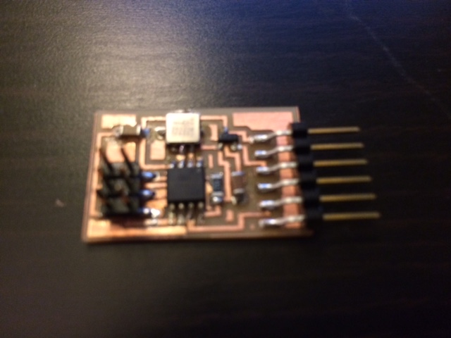
For simplicity, I began with Neil's 2-axis accelerometer board, seen below. This board makes use of a MXD6235 2-axis accelerometer. The board is pretty simple compared to previous boards I have made, with the exception that it uses a voltage regulator to bring down the voltage from 5V to about 3.3V before reaching the accelerometers.
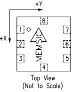
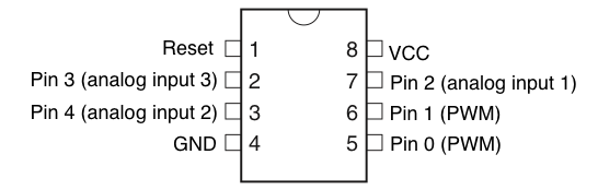
The accelerometers themselves are also pretty simple, having only 8 pins. These pins, in order according to the schematic below, are (1) Power down, (2) connect to ground, (3) connect to ground, (4) do not connect, (5) do not connect), (6) Yout, (7) Xout, and (8) 2.7V to 3.6V Voltage source.
Input Reading
So this is the fun/hard/learning/difficult/Idon'twanttodobutI'mexcitedfor part. Given that during embedded programming week I focused on talking to my board using the Arduino IDE, I did the same thing again. Before starting, I had to determine Arduino ATTiny45 pin layout (not the physical numbering layout). A quick google search revealed this answer.
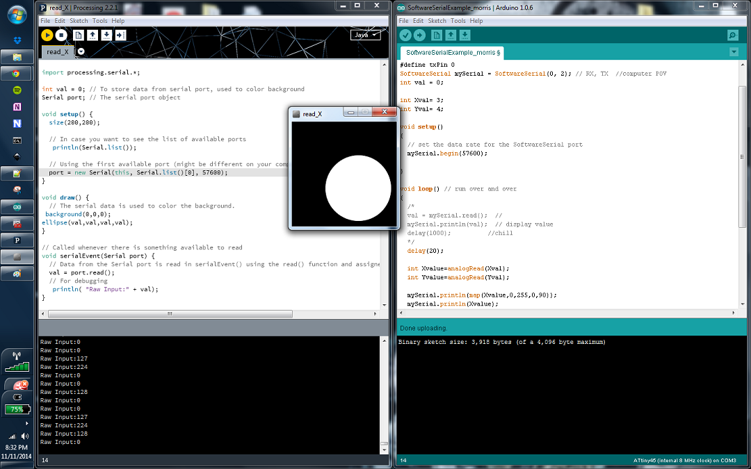
The Arduino code is fairly simple, after I understood what I was doing. Mad props to Diego and Matt from the architecture section for helping me understand exactly what I was doing. From reading the data sheet on the accelerometer, I realized that it prefers digital communication. This means that I cannot use the standard Arduino "Serial" commands, since these are analog. Instead, I had to include the "SoftwareSerial.h" library. I instantiated the RX and TX pins (From the computer POV), picked the Xval and Yval (the pins I am reading from in the accelerometers), and began my SoftwareSerial object at 9600 Hz. In my loop function, I "analogRead" the pins from the accelerometer, mapped the highest and lowest values to between 0 and 90 degrees, and println-ed them. The Ardiuno code, along with all the commented stuff that didn't work, can be found here.
I then used processing to read in what my board was doing. I used processing because I have heard it is great for visualization and I want to get comfortable with it. The Processing environment did a similar thing to the Arduino code. First, I created a serial port object, listed the available ports on my computer, chose one to listen on, and drew shapes as the raw data was read. I also created a function called SerialEvend, which only responded when a new port was read. Just for fun, I had a circle be drawn on a small square when data was read. The four inputs for an ellipse in Processing are x,y,a-radius,b-radius, thus, as the data was read and the value of the accelerometer increase or decreased, the circle was sized appropriately. The Processing code, along with commented code, can be found here.
Final Words
I am not sure why, but the data is still very noisy. My next step will be to be able to compile C code and simular my GUI using python, much like Neil does. This way, I can use his board designs and examples to trouble- shoot my work. I will keep you updated as this continues forward.
Update: Compiled with C
Finally was able to compile with c!
How to add c code to your microcontroller
To check everything is connected correctly. "avrdude -c usbtiny -p attiny45" *be sure to use the right 44, or 45*
Type "make", this will run the first function in makefile, and any associated functions.
Type "make program-usbtiny" to send your c code to the micro controller.
While in the directory of the C code, type "C:\Python27\python.exe hellow.accel.45.py COM3" The bar changes according to the x tilt of the accelerometer.
VIDEO PROOF!.