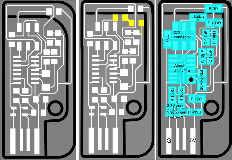
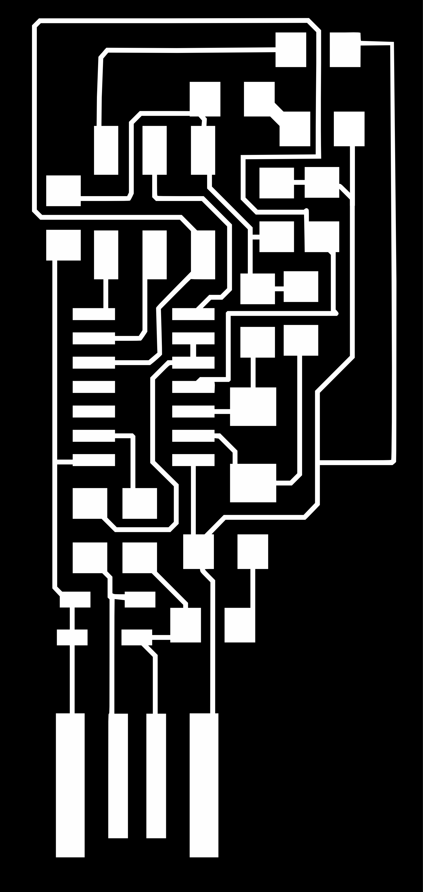
Rendered Inkscape overlay - "Valentin" FabISP modified for a power indicator LED
We were pointed to a few choices on FabISP designs: Neil's FabISP, the FabISPkey, and the Valentin. I chose the Valentin, which had the combined features of small size, an on board USB connector, a key ring, and a snap off design. I also wanted to modify it to add a power indicator LED. I first imported the board .pngs into Inkscape, and used the trace bitmap tool with multiple scans without smoothing to make a vector representation of the png. With all the traces as objects in Inkscape, I could easily select subsets to move around in order to modify the board. In the image above, the left is Valentin's original board, and the right is my version. I extended the board by altering the exterior cutout, and moved some traces around so I could add a few additional pads (in yellow) for a resistor and an LED. These pads bridge the power and ground rails, making for a nice indicator. I found the LED datasheet by following the part number from the fab inventory page. The green LED had a pretty typical (worst case) voltage drop of 2.1V, meaning a 499ohm resistor from the 5V rail would be more than sufficient to keep the current under the 20mA maximum current of the part.
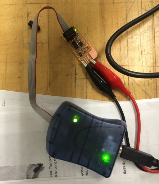
Programming the LED modified Valentin
Unfortunately I don't have images of the initial construction, but here is an image of programming the FabISP Valentin. A few comments on the assembly: Milling the FabISP wasn't too difficult, but there were some tricks. My first attempt didn't work due to the 1/64th endmill not being correctly zeroed and the board not being properly taped down. It only polished the copper a bit and cut on one side. After retaping, rezeroing, and hitting down on the modela 2 times after zeroing but before cutting, it made clean cuts for the traces. However, the toolpaths being created by fab modules weren't quite right and some shorts existed. By decreasing the tool diameter parameter (0.3mm 1/64 endmill, 0.5mm 1/32 endmill), the path was generated correctly and everything cut like I wanted. Overall, it took 2 1/64 runs and 2 1/32 runs. This was fine as the Modela is high resolution enough that as long as everything is zeroed properly it will cut in the exact same places. Programming was a bit tricky as well. First off, this resource on what the AVRISP mkII's lights mean was quite helpful. I guess I didn't read the instructions properly as it took me awhile to figure out that the FabISP needed to be externally powered. In the image above I'm powering it off the bench power supply. I also installed some 499k resistors instead of 499ohm, which took a while to figure out. Next, I tried to compile and install the firmware on my mac. I installed the avr toolchain using MacPorts, but could never get the thing to program properly. The error log is here. In short, it seemed to program successfully, and then failed with "avr_read(): error reading address 0x0000 read operation not supported for memory "signature"". No idea what the issue is, but I tried again from the Ubuntu computer running the Modela and it programmed perfectly.
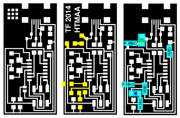
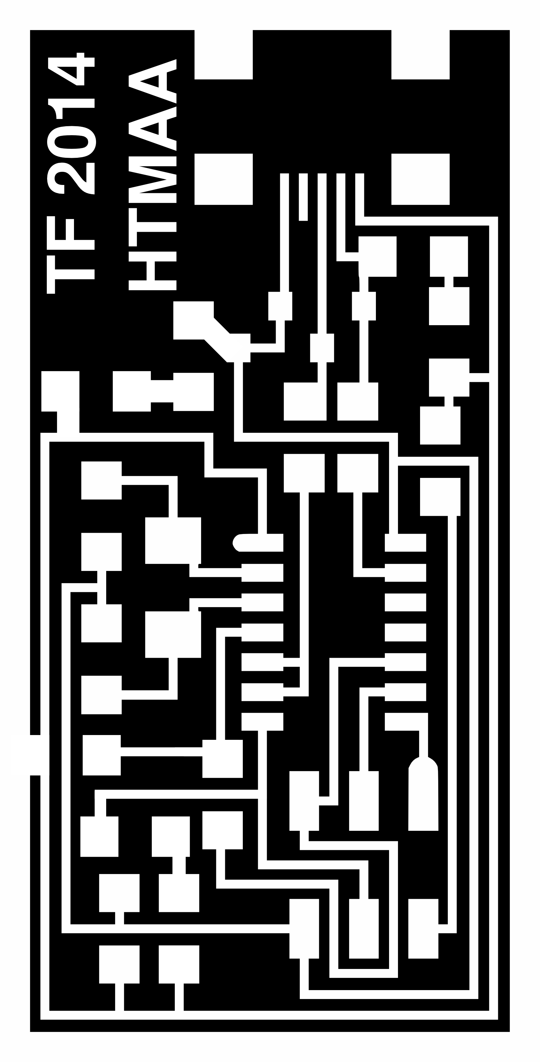
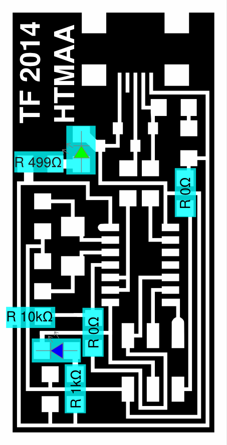
Modifying Neil's FabISP for more blinkage
The Valentin worked fine, but it seemed a bit little fragile, and having to plug it directly into my laptop's USB port made it harder to work with. I also still wanted more LEDs, in particular I wanted LEDs that would flash with activity. The USB data lines seemed off limits due to their low current sourcing capability and expecting certain impedances. On the other hand, the MOSI / MISO, SPI lines were being driven by robust microcontroller pins that could source/sink enough current to light an LED. I went back to Neil's FabISP, moved some things around, and took advantage of the extra space. The left side in the image above shows Neil's original design, while the middle and right images show my modifications. I added two LEDs: one green power indicator like the last design, and a blue LED going from 5V to the MOSI trace for the ICSP connector as an activity indicator. I found this helpful document on Atmel's ICSP protocol. When there is no data transfer, the MOSI pin is in a high impedance state. However, when data is being transfered, the MOSI pin on the attiny44a is asserting either 5V or 0V. The 0V state sinks current through the blue LED, thereby lighting it up only when a data transfer is being attempted through the ICSP connector. According to the attiny44a datasheet, the I/O pins on the micro can sink/source ~40mA. In theory that is more than enough headroom to drive an LED while simultaneously asserting digital logic. I put a 1k ohm resistor to current limit the LED, by eye the blue LED flashes as bright or brighter than the green LED. In actuality I'm unsure if the addition of this LED on the MOSI trace will affect the programming process, as I haven't yet tested it directly. That being said, the LED can easily be removed or the resistor changed to a (less disruptive) high resistance value if it significantly affects the robustness of the programming process.
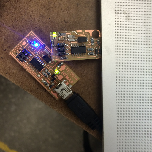
FabISP-LED and FabISPKey-LED
End product turned out pretty well! If you're wondering how I took a picture of the blue LED (purportedly only active with activity): I entered sudo make fuse on my computer while simultaneously taking the picture. This makes the FabISP briefly ping for things to program on its ICSP connector. Overall I really enjoyed making circuits on the Modela, really neat way to rapidly prototype circuit boards. Source files below:
Source files
Original design: Valentin HTMAA 2011. Modified by Tim Fallon HTMAA 2014FabISPKey-LED Valentin Inkscape .svg source
FabISPKey-LED Valentin cutout .png
FabISPKey-LED Valentin circuit .png
FabISPKey-LED Valentin circuit annotation .png
Original design: Neil Gershenfeld. Modified by Tim Fallon HTMAA 2014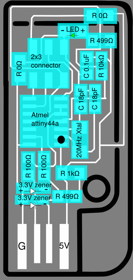