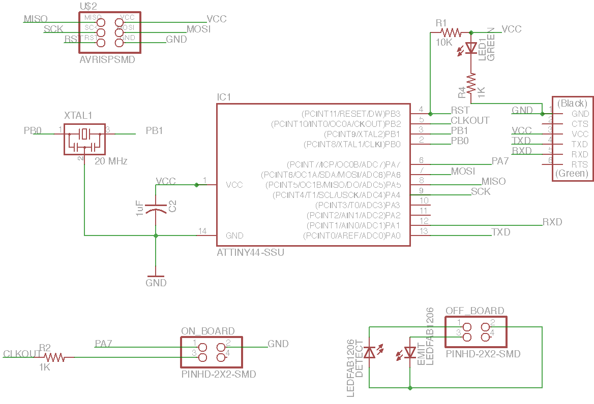
Schematic
I started the assignment by modifying my previously designed board. I removed the switch, the extraneous LEDs, and the MOSFET. The picture shown here is actually the 2nd revision. After heading into the Fab Lab and seeing that Morgen was building a two-piece board, I thought that was an interesting design and went back to redesign my board. I added some 2x2 connectors and moved the light detection LEDs onto a separate board, and planned to connect them with a 4-wire ribbon cable. The LED board only needed 3 connections, 1 for ground, and 2 pins for the emitting and detecting LEDs respectively.
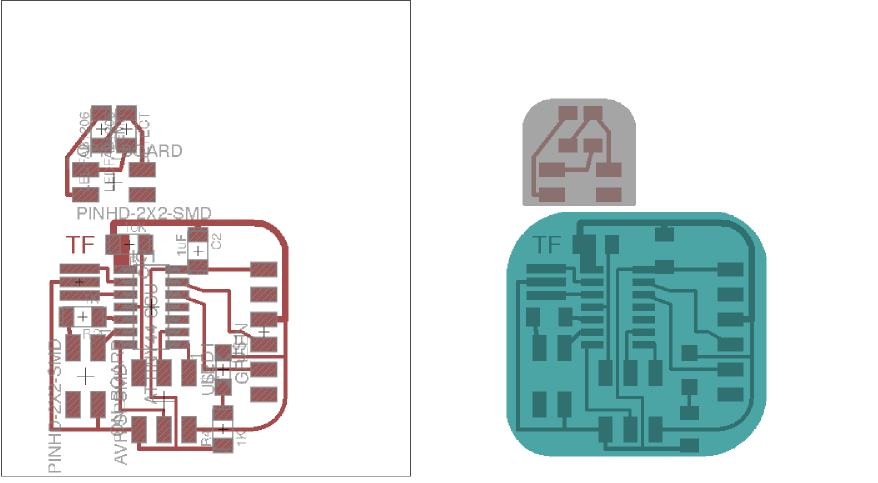
The pads and exterior cutout for the board
I'm not sure what the official protocol for designing two part boards is, but in my case I kept a merged schematic and trace design and just milled out two using a two piece exterior mask. I used the "measures" layer for the mask for the smaller board. A note: I actually made these boards too close. Fab modules didn't want to cut the spot between the two boards, as there wasn't enough clearance for the offset of the tool. I had to adjust the tool diameter down to get the paths to calculate correctly.
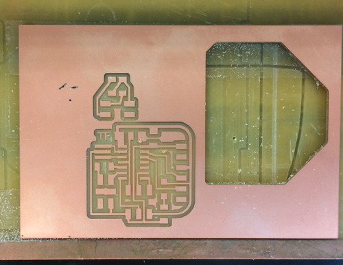
Part successfully milled
The modela mill went well. I did experiment with some of the fab module settings this time, notably the number of offsets. I reduced the number of offsets to 1 instead of 4, which made the modela mill the absolute minimum. Although the milling was extremely quick, I thought soldering without enough free space would be problematic so I went back and milled it out with the full 4 offsets.
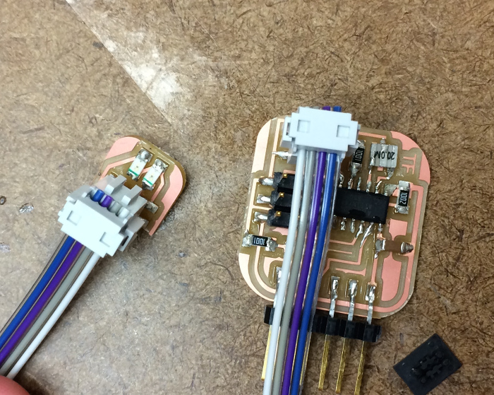
Board soldered up with design flaws starting to become apparent.
Once I soldered the board, I started to understand that I had some real design errors on my hands. Firstly, the way the off-board connector was designed, the ribbon cable had to go over the main board, thereby precluding programming the board through the ISP header at the same time as having the LED sensor be attached. I did fix this by cutting the ribbon cable and putting a half turn in it, but unfortunately the plastic connector on the ribbon cabble for the LED board still blocked the ISP ribbon cable from attaching. Secondly, the LED board (which was meant to have a finger placed over the two LEDs), was too small. You can't really put a finger fully on the LEDs, as the plastic connector for the ribbon connector on the LED board physically prevents it. Really these design issues could be handled by not making such a tiny board. A bit of extra clearance in the design would solve both problems. In short: don't make things needlessly small, as it could led to physical problems with the downstream assembly. In a broader more important sense, always consider the physical reality of your design.
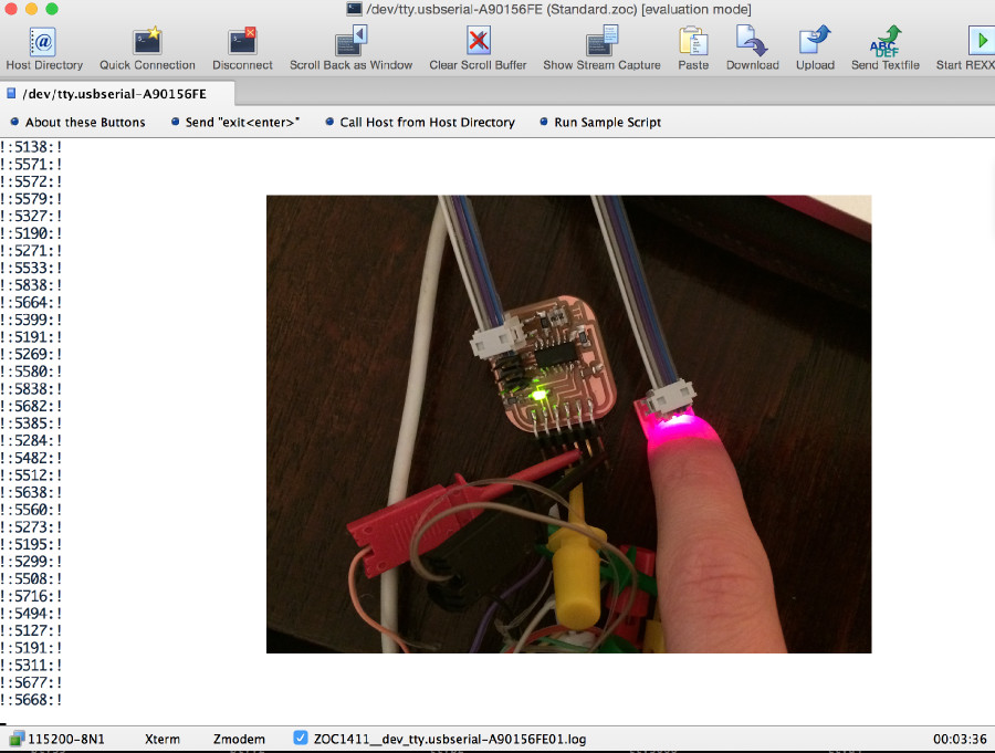
Test setup: Ambient light
Here is a the board in the test setup, overlayed over the serial communications. I am doing the serial communication and power with the Bus Pirate, and recieving the serial communications on my laptop with Zoc6.
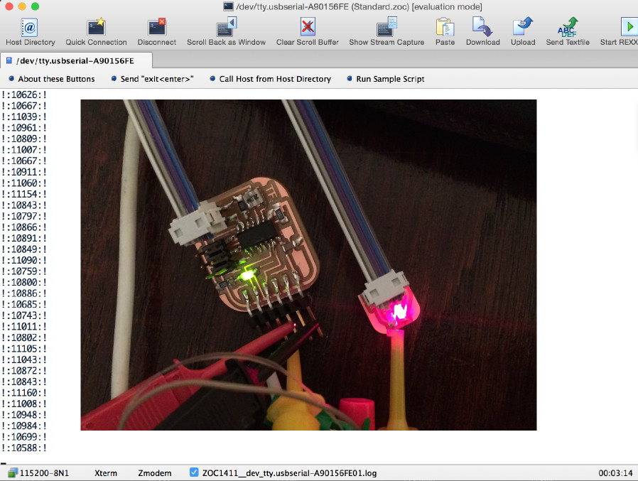
Test setup: Finger on LEDs
With my finger on the LEDs: the value reported by the board (cycles needed for the pin to discharge), goes down, indicating higher levels of light!
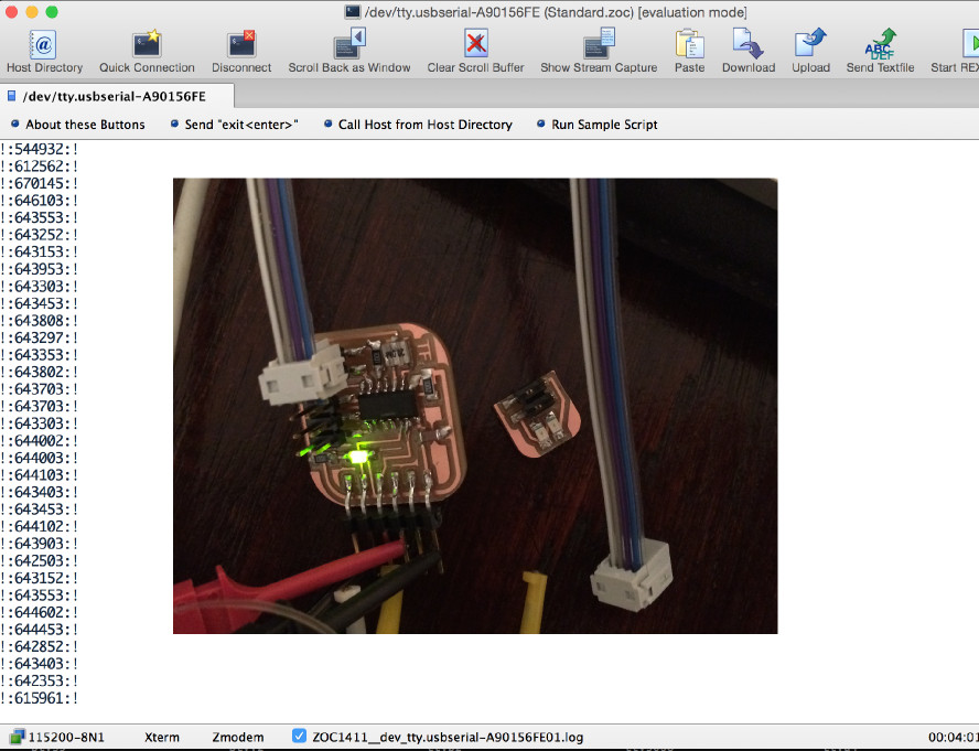
Test setup: No LEDs connected
Without any LED at all: the cycles needed for the pin to discharge get quite high. Even though the microcontroller is waiting for the pin to discharge for 100,000s of cycles, the program still works as the microcontroller is so fast compared to "human" timescales.
Still to be done: keep programming the board so the reflectivity is measured instead of just intensity. As Neil described, this is a software analysis which pulses the emitter LED on and off, and measures on and off cycles times. By comparing them, it is possible to detect reflected light specifically.