Electronics as Tools
CIRCUITS do so many things. They make our lives convenient (think of cell phones or thermostats). They give us new interfaces with each other (think of laptop computers, email, and FaceTime) and with our world (think of modern cameras). Circuits are the foundation for electronics- in things we make, they are the circulatory system for electricity. If we knew how to create them, we could build circuits that help us extend our abilities to understand and empathize with the natural world. Let's make one.
The circuit we will make this week is a PCB - printed circuit board. These are often made with chemicals, but we can make them in non-toxic way using a computer-controlled tool that cuts away unwanted copper from a surface. Here are some of the steps we'll do:
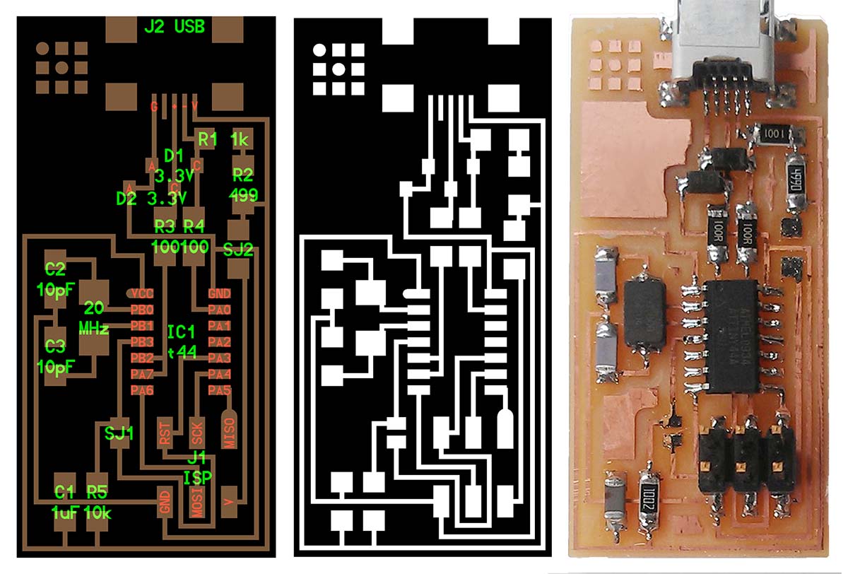 ^ Starting on the left, this is a computer-aided design of a circuit, complete with labels for each component (among other abbreviations, C stands for capacitor, R stands for resistor, and D stands for diode). The middle image shows how this design is communicated to the mill (the tool that cuts, or 'mills,' out the circuit from the blank copper pad). The right image shows a finished circuitboard.
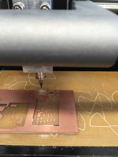
^ Here you can see how the circuit is cut into the board by the mill. Imagine a tiny, controlled 'drill' (although the bit is slightly different) moving across the surface removing copper to create roadways for electricity.
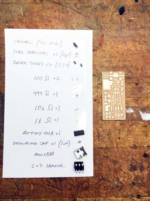
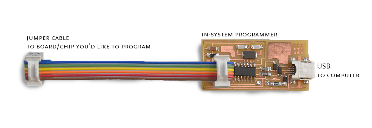
^ After this board was cut, I picked out the electronic components required to build the circuit. In this case, the circuit is designed to be an in-system programmer- a device that can be used to program chips in other circuits to accomplish other tasks. Making this is a bit like a carpenter first learning to make a handle for his hammer— a tool to make other things. The cost of all these little bits is just a few dollars.
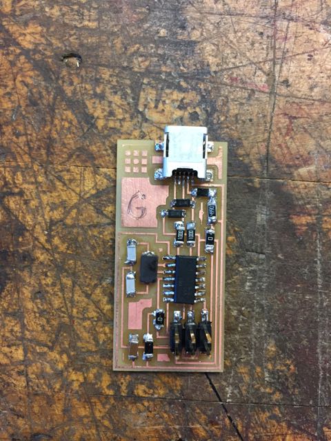
^ After a little bit of soldering and a little bit of personalization, I'm left with this finished circuit. Each of the elements was first 'tacked' on to the surface roughly, and then a little more solder was added to make sure things conducted properly and are well-connected.
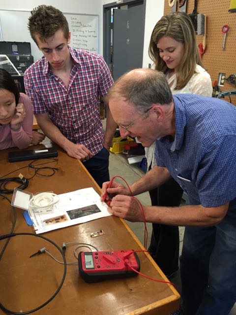
^ Here, Elizabeth and Glenn look on as Rob shows us how to test a final circuitboard using a multimeter. A general approach is to first identify the ground pin on your circuit and then probe various locations to check whether voltage is either zero (other ground locations) or 5 V (the input USB power level our circuit and 'brain' chip likes). You can also probe the resistances across different elements to make sure contacts are all conductive and resistors are the correct rating.
After this initial check, the ISP (in-system programmer) was itself programmed by connection to the lab computer and a sequence of command lines. Then I used an oscilloscope to measure the vibration of the quartz processor crystal at 20MHz- this was cool! This little crystal gives the system an internal 'clock' to help execute sequential tasks. Here's how it looks once it's all put together... I etched a 'G' on it to help with identification.

Circuits are the foundation for all computers; one of their many possible uses is to track endangered condors. Can you imagine others?