Xin Wen
Week 11: Input Devices
1. Fabricating the Board
2. Programming the Board
3. In Action!
4. My own board.
This week's assignment is to make an input device. I decided to use the step response to make Neil's transmit-receive board to understand how it works. One of the input for my final project is going to be pressure so I wanted to understand how step response works to make a pressure sensor later.
1. Fabricating the Board
Fabricating the board is fairly simple since I have done it a couple times by now. I used the traces and outline from the class website. I also have been getting faster at soldering compared to when I made the first board in week 2. I found a soldering temperature at 660F works the best for me.
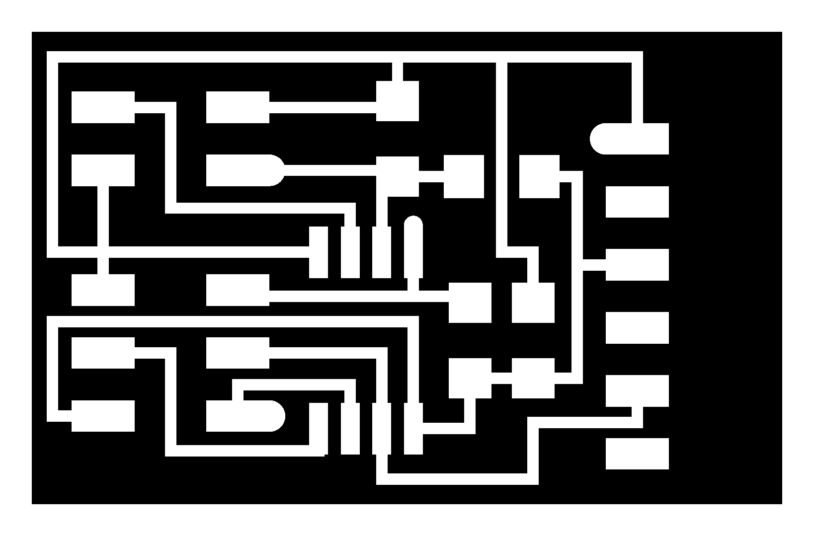
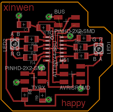
Figure 1. Traces of the TxRx board.

Figure 2. Outline of the TxRx board.
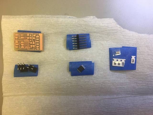
Figure 3. Components of the board.
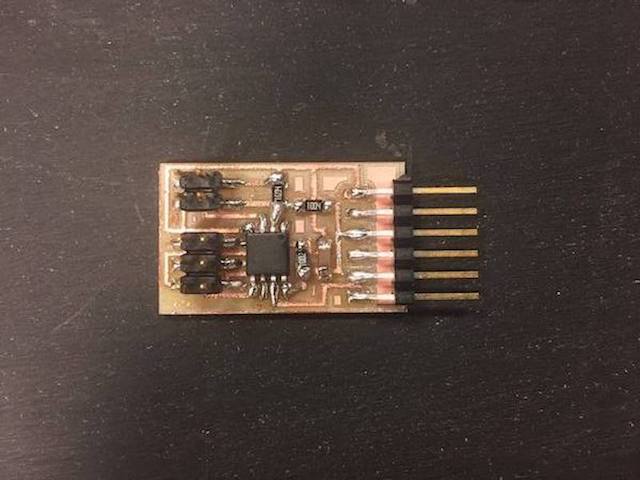
Figure 4. Soldering done!
2. Programming the Board
Magically, there was no connection issue this time! I was able to program it without having to resolder anything. It's pretty amazing how much this board can do with so few components. I used the make file provided by Neil and ran the following commands.
- make -f makefile_name.make
- make -f makefile_name.make program-usbtiny
I then used Neil's python code to bring up the visualization by running
- python hello.txrx.45.py /dev/tty.usbserial-[your serial port]
3. In Action!
I connected Tx and Rx to one copper plate each, and connected the two GND pins together. At first, the visualization didn't respond to my touching either plate. I was suspecting that I messed up the order of the 2x2 pin header so I found another empty header (without rainbow ribbon) and figured out which pin goes to each wire in the rainbow ribbon. I was indeed connecting Tx, Rx together while taping the two GND to the plates. After I fixed that, it responded to me touching the plates!
4. My own board.
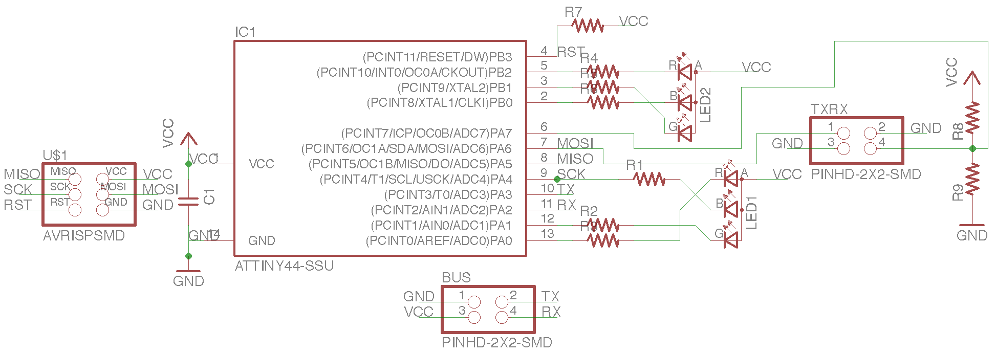
For the pressure sensing on my own board, it's very similar to Neil's design but it detects if certain threshhold is met. Here's the schematic and layout. The thing to be aware of is that the step response need to be read through an ADC pin.