networking and communications
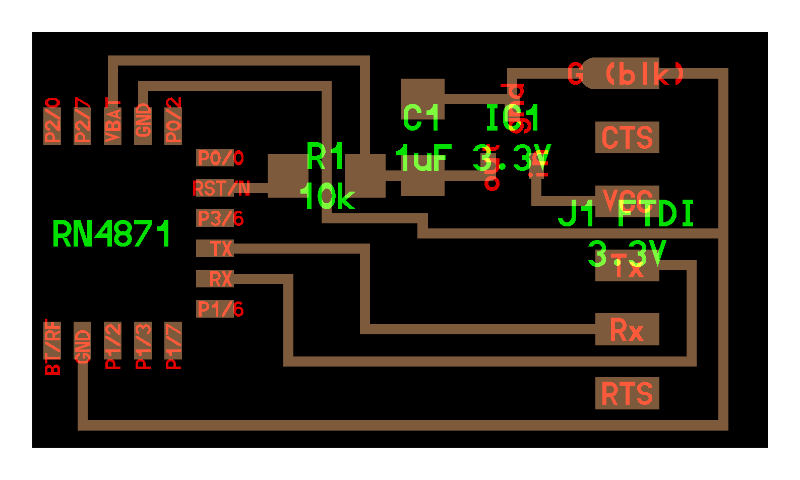
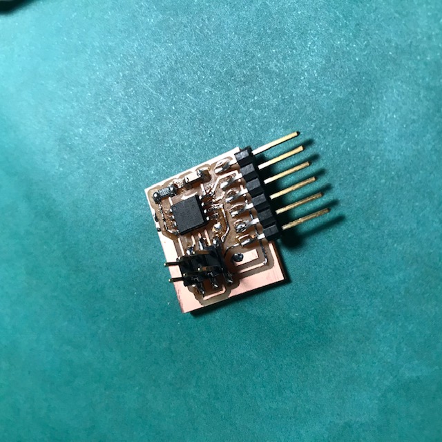
This week, we made a thing that could talk to another thing. AKA I played around with RN4871 2.4GHz bluetooth module. I basically remade Neil's board , but with an LED added to indicate that things were working. I followed Rob Hart's tutorial to get everything set up. I only added one LED (green with 499ohm resistor)(to P0/2 and not P2/0, which is I think what Rob did). This LED turns on and does some blinky type stuff that indicates the board is working.
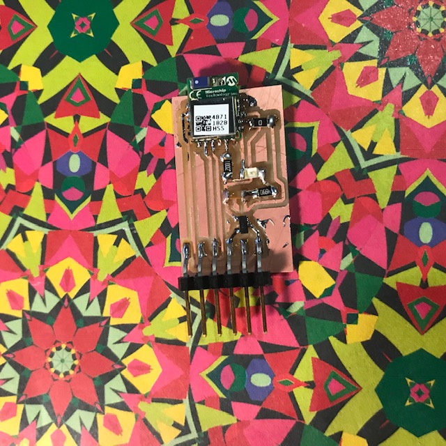
That's a photo of the completed board.
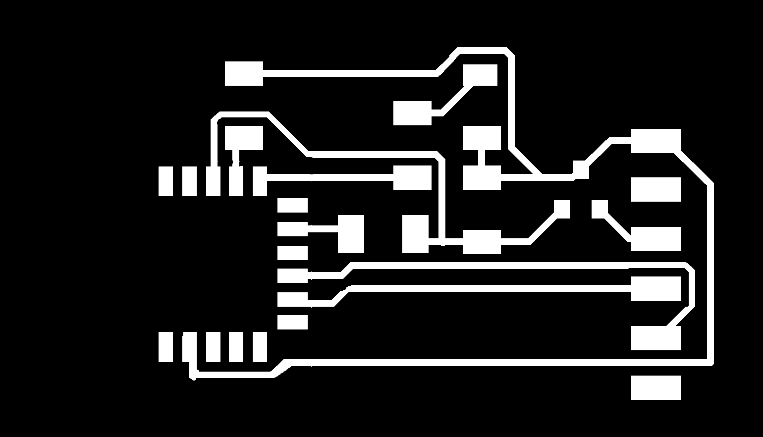
These are the traces. Something not super interesting is still happening with mods for me, which is that when I calculate a tool path from mods while at the EECS shop, it seems to assume that the mill is larger than when I calculate a tool path from mods from my laptop, and I don't understand why this is happening? The mill diameter, min cut depth, etc. is all the same, I think? Anyways, so that keeps happening. Which is easy enough to deal with.
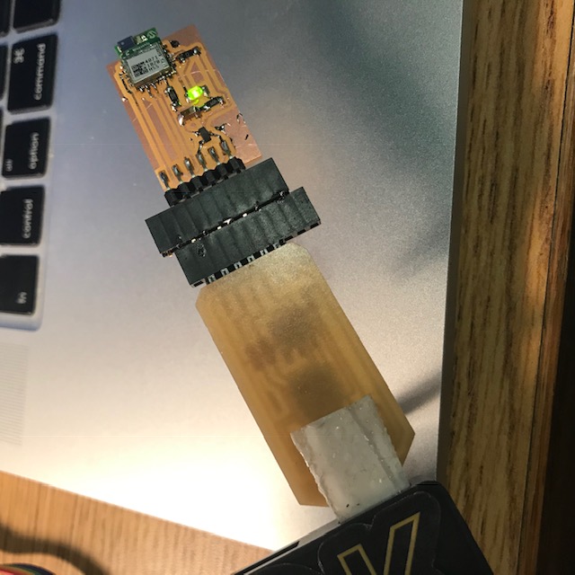
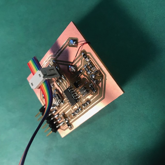
Here's a photo of the board (with LED on!) plugged into my FabFTDI board.
After making the board, I installed BLE Scanner onto my phone (an iPhone). This app alledges to have been made by the same people as the identically named Android app that Neil uses in this video. Though the UI is different and tbh kinda worse. In Neil's video, the board shows up named, and I couldn't figure out how to do that. And in the tutorial that Rob linked to, the board shows up named RN4871. When I went searching for it, my board just showed up as BLE-A8AC which seems terribly generic.
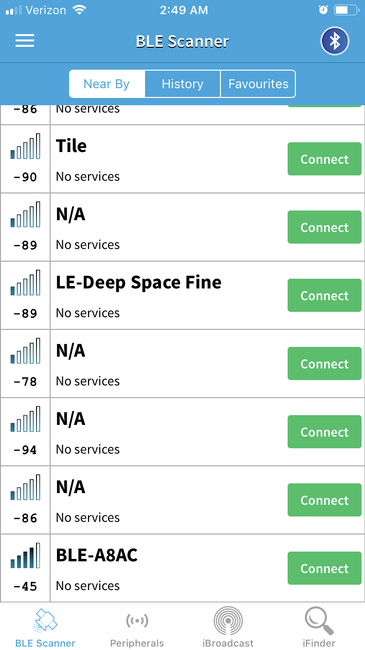
The above picture shows how it was listed. I identified it as my board because it had the strongest signal, and that signal would change as I moved around. I also found it concerning that it was listed as having "no services" because this was inconsistent with Neil's video and Rob's tutorial.
From there, I followed Neil's video and ran miniterm.py to configure the board and then to communicate between it and the phone. The things I did here that were dumb were 1. I forgot to call miniterm with a baud rate and couldn't figure out why nothing was happening and 2. miniterm will not necessarily display what you are typing and that's just a little disconcerting.
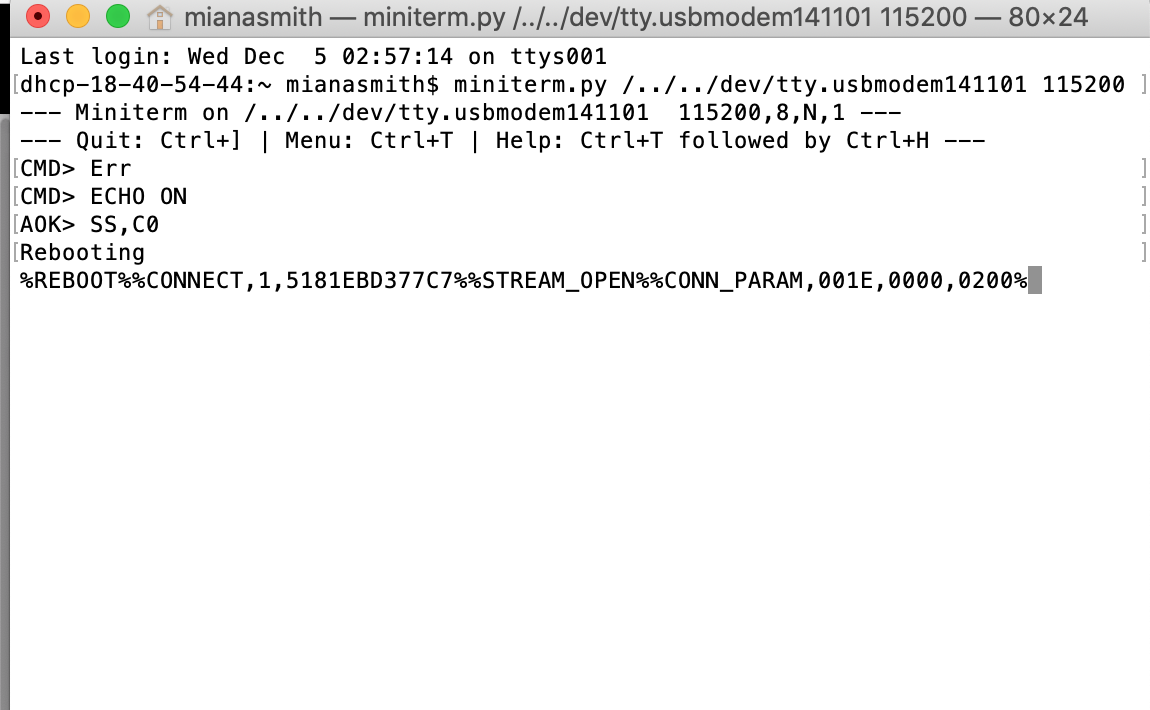
It was an exciting moment when a bunch of numbers that I don't know how to interpret ran across the screen.
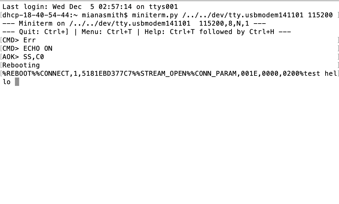
It was even more exciting when there was communication between the bluetooth chip and my phone. I typed "test" and "hello" in from the BLE Scanner, and would you look at that, they appeared on my serial connection!
I did have a false start with that though, in that BLE Scanner listed several services which the RN4871 could do, but it looked like only one of those services would actually communicate back through serial. I don't know why. I should find out, probably.
Also, this week I tried to make an RFID reader/writer with an attiny44. (And also an RFID tag with an attiny45). None of that is working yet, if it will ever work...
This board is a programming board for the attiny45. I've seen other projects that use an attiny85 (there's one (attiny85A or something like that) that's meant to run at really low voltages, like ~1V, which makes them ideal for something passive like rfid. However, I've also seen a project that uses the normal attiny85, so I was hoping that this would all work on a normal attiny45 as well). The way attiny-as-rfid tag works is you basically just have to stick an appropriately inductive inductor across the CLKIN and CLKOUT pins. And then, more ideally, the inductor is wired in parallel with a capacitor so you have a 125kHz resonant LC tank. The attiny uses the LC tank as an external clock, and also as an output/input with each clock cycle.
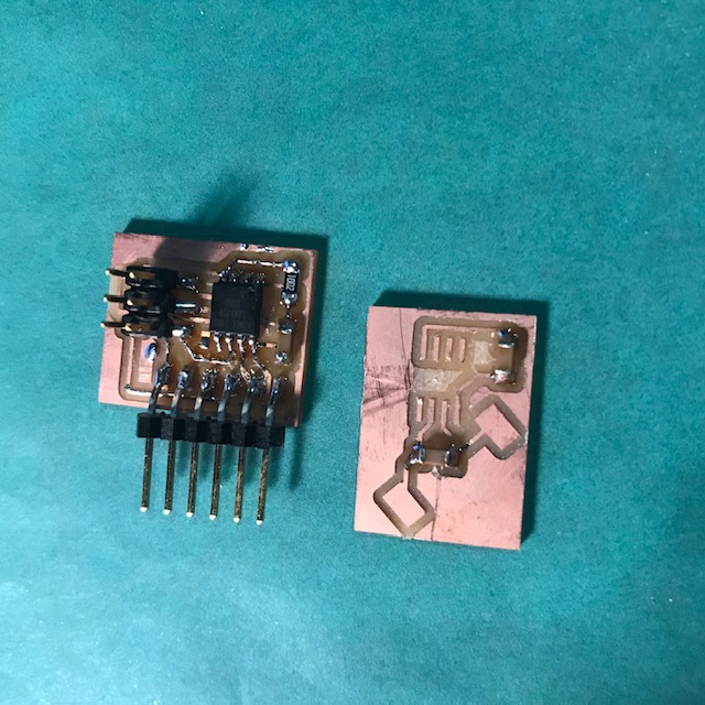
Another photo of that board, plus the tag board (which is missing a coil and the attiny45). The tag board has a 1uF capacitor going to the LC tank and another .1uF capacitor going between ground and vcc, because the attiny datasheets suggested doing that, and I saw another rfid project that seemed to suggest this would help clean the data a bit. The board also has two breakout pads for an inductor.
Aside from those, I was mostly trying to make an rfid reader with an attiny44. So that would primarily be the attiny44 and another 125kHz lc tank. The attiny would output a 125kHz PWM signal to the LC tank, and then read a filtered signal from across the capacitor. To this end, I made one board, which turned out to have foot prints for parts we didn't have in stock (and also may just be over complicated)(and also wrong).
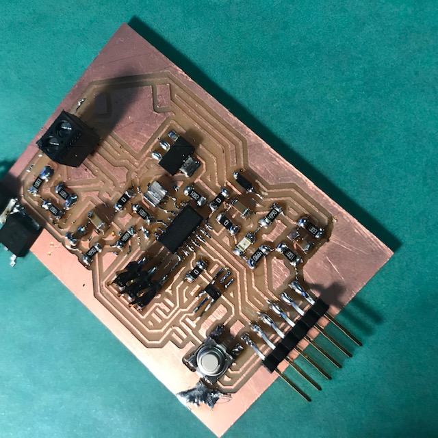
Hm, parts with the wrong foot print are the op amps and the n-channel mosfets. Also, I'm pretty sure I wired the MOSFETS up wrong. Like even if everything were connected, I highly doubt this board would work. Also, I don't super duper get op amps, so the resistances I picked might've been unreasonable.
I decided to make another board that's a lot simpler.
This board is based on a project you can find here. This person makes a reader/writer using a Nucleo dev board, and this may just be because I don't properly understand what's going on, but I feel like you don't need the additional functionality of a Nucleo for this application.
So I'm still working on these boards, but the second reader seems promising? I need to look at some signals from it with an oscilloscope. I really don't trust the inductor I made to be at all reasonable.