making a
push pedal for
a conveyor belt :
push pedal for
a conveyor belt :
stepper board using an atmega328p :
This week we were asked to add a sensor to a circuit board.
In order to direct this assignment to my final project, I wanted to make my input device a push pedal to control my conveyor belt.
Immediately after class this week, I asked Anthony what would be the best way to do this, and he said there are many many ways to go about it - the easiest would be to use a limit switch and have the pedal push on it. The more complicated way would be to do it using the step response.
This week I'll be attempting the step response for my push pedal because I think it'll be more of a challenge than a button, which we've already included in our previous boards, and because I think it would allow me to switch the conveyor belt to be on/off to increasing speed depending on how much the pedal is pushed.
I asked Anthony if I would have to change anything in order to program the board using Arduino IDE, and he said I should switch the attiny45 for an atmega328. You could use neil's board as is, but then you would have to install software serial, which does not alwaysssss work!
So I went ahead and did that.
neil's step response board (transmit / receive) :
To be clear - I used Neil's step response board, and just switched out the attiny45 with the atmega328.
To be clear - I used Neil's step response board, and just switched out the attiny45 with the atmega328.
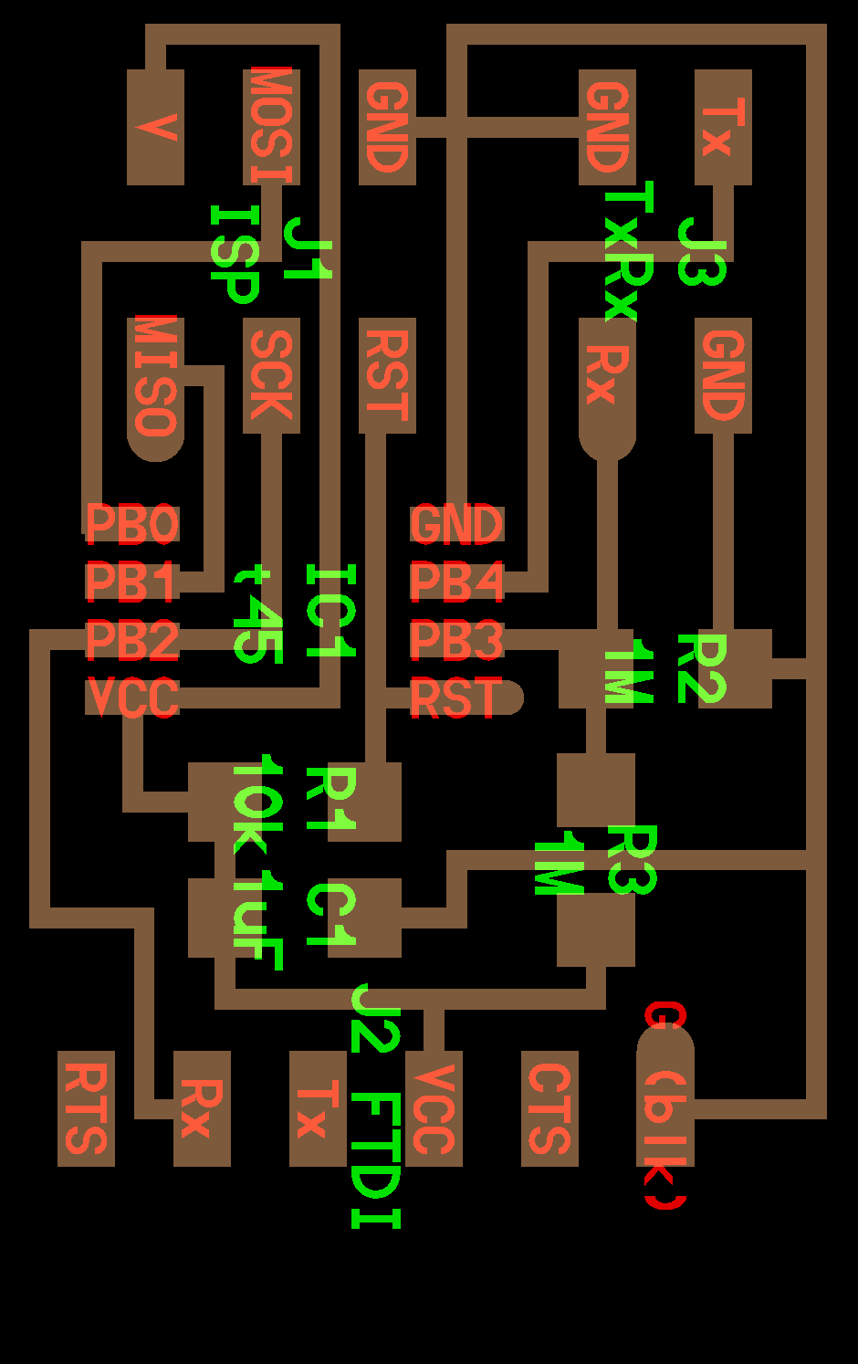
schematic on eagle :
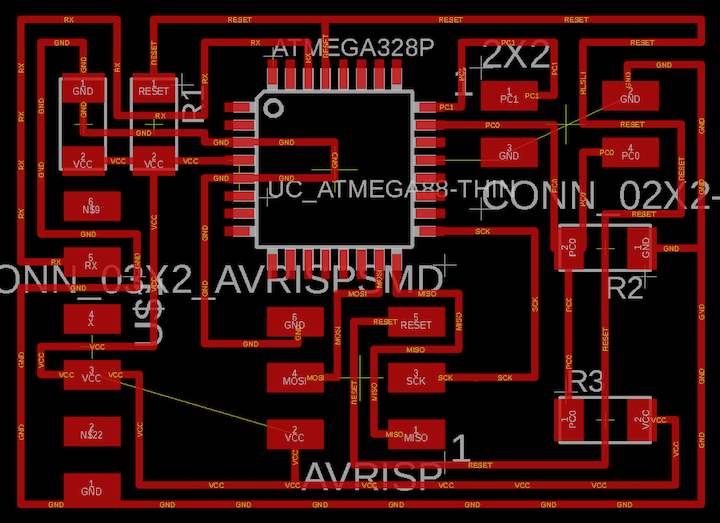
board on eagle :
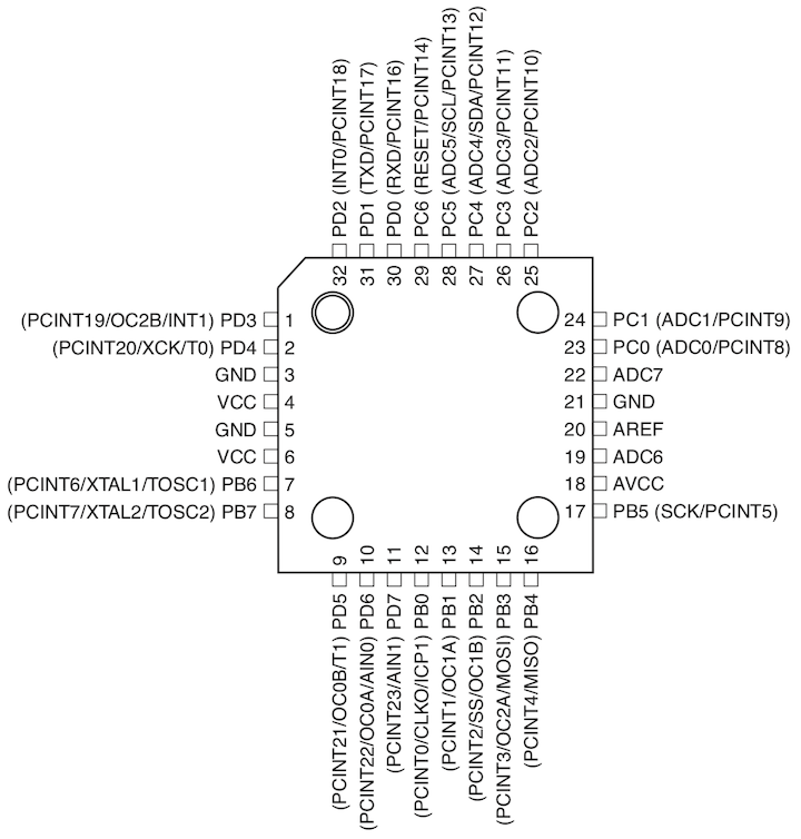
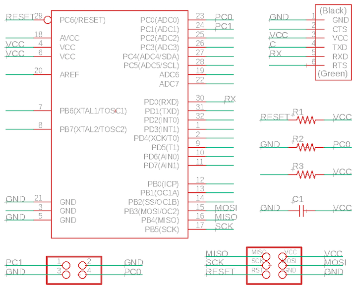
atmega328 pin out :
the atmega does differ from the attiny in a few ways - you'll notice in the pin out that there are specific pins dedicated ot miso / mosi / sck - which I don't think is the case in the tiny24.
there are also more than one GND and VCC - i imagine this is because once you start using this, you'll probably have a lot of components on your board and that makes it complicated to arrange everything so that it all connects the way it should.
in any case - Eagle is pretty easy to use at this point. I did take a bit in terms of arranging the board in a neat way. I am a bit OCD about how the traces turn and align throughout the board, so I took my time to make the board look nice.
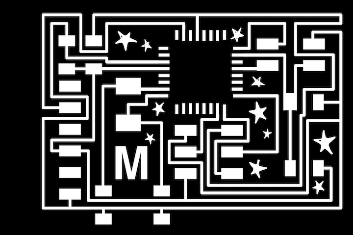
final traces :
I tried to space things out a bit more this time.. The last few times I've always tried to make the smallest board possible and that ends up being kind of a pain just because for whatever reason eagle doesn't catch traces that wouldn't be properly milled.
I tried to space things out a bit more this time.. The last few times I've always tried to make the smallest board possible and that ends up being kind of a pain just because for whatever reason eagle doesn't catch traces that wouldn't be properly milled.
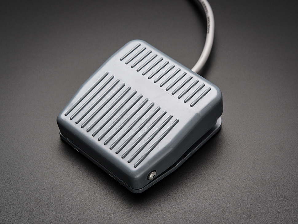
foot switch :
I again naively purchased a product on adafruit - no ragrets.
I want to mill a really beautiful push pedal, but I kind of wanted to buy a really simple one just to take it apart and see how it works. Turns out its pretty simple. There's a spring inside, and this footswitch has a limit switch inside.. so I guess worst case scenario, I just make a button board if this step response doesn't work out.

pedal test :
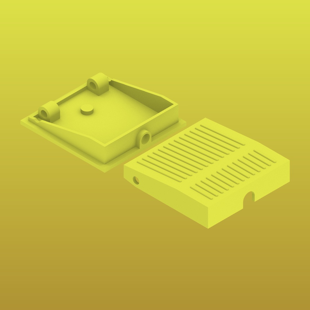
two stls sent to 3d print on abs printer :
for now, i re-modelled the pedal and sent to 3d print. I kind of want to see if this copy works and if it does, I can use to test the input device / board, but I can also make a nice pedal and hopefully mill it, not just print it..... but i suppose i don't necessarily have to finish the pedal this week - though that would be nice.
for now, i re-modelled the pedal and sent to 3d print. I kind of want to see if this copy works and if it does, I can use to test the input device / board, but I can also make a nice pedal and hopefully mill it, not just print it..... but i suppose i don't necessarily have to finish the pedal this week - though that would be nice.

2 incorrectly milled boards :
On Sunday I milled my board and encountered some errors.
The first board, I made the mistake of using a 1/32" bit to mill the traces. On the second attempt, the 1/64" bit seemed to be old or have some kind of issue because my traces were furry and they were not easy to clean - like when you use a brand new bit.
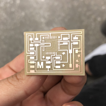
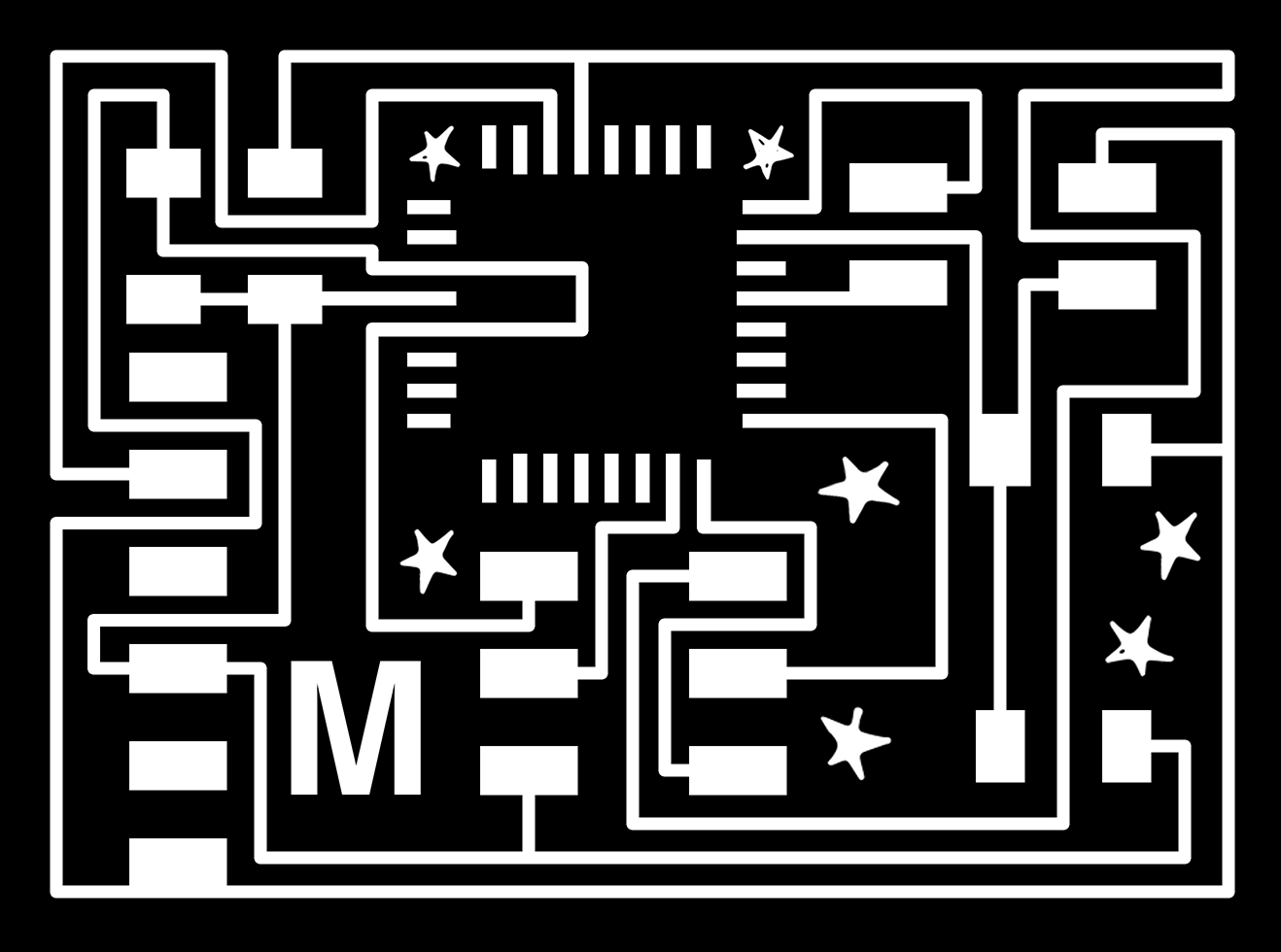
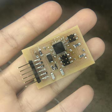
nice traces :
on the third attempt, I was able to mill the board correctly. I will add that I didn't really have issues with traces not being milled, so I think in general its probably best to not try to make the smallest possible board, ha.
on the third attempt, I was able to mill the board correctly. I will add that I didn't really have issues with traces not being milled, so I think in general its probably best to not try to make the smallest possible board, ha.

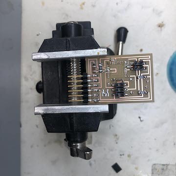
making sure scale is correct :
I'm a bit nervous to solder the atmega - it really is so tiny. I spoke to Diego soon after milling my board and he recommended soldering the atmega traces, cleaning them w the braid, then adding the mega, re-soldering, and re-cleaning with the braid - so you clean the solder twice.
I'm a bit nervous to solder the atmega - it really is so tiny. I spoke to Diego soon after milling my board and he recommended soldering the atmega traces, cleaning them w the braid, then adding the mega, re-soldering, and re-cleaning with the braid - so you clean the solder twice.

soldering traces before placing atmega :
surprisingly, I was able to be careful enough to not need to use the braid - which I was relieved about because I have not successfully been able to use the braid at this point.
surprisingly, I was able to be careful enough to not need to use the braid - which I was relieved about because I have not successfully been able to use the braid at this point.
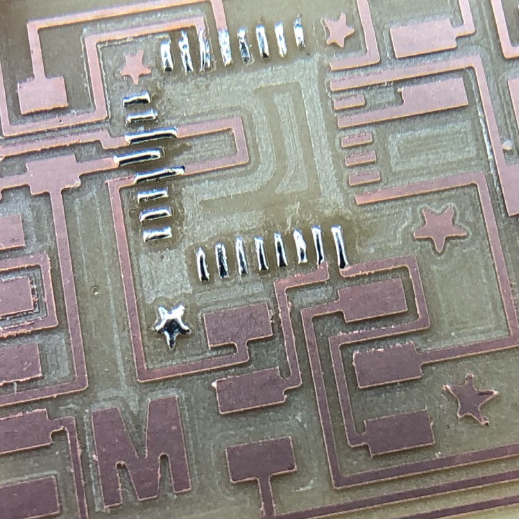
close up :
it wasn't even super difficult to place the atmega - I did unfortunately join two pins, and after a lot of work was able to unjoin them.. But in total, it took me around 2 hours to solder - anddd even though I used the magnifying glass, I think I strained my eyes!
it wasn't even super difficult to place the atmega - I did unfortunately join two pins, and after a lot of work was able to unjoin them.. But in total, it took me around 2 hours to solder - anddd even though I used the magnifying glass, I think I strained my eyes!
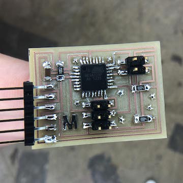
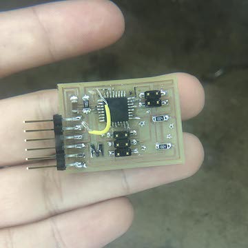
components soldered :
ok so - now, assuming i made the board correctly, i'm going to try to program this using arduino IDE.
ok so - now, assuming i made the board correctly, i'm going to try to program this using arduino IDE.
atmega pin out:
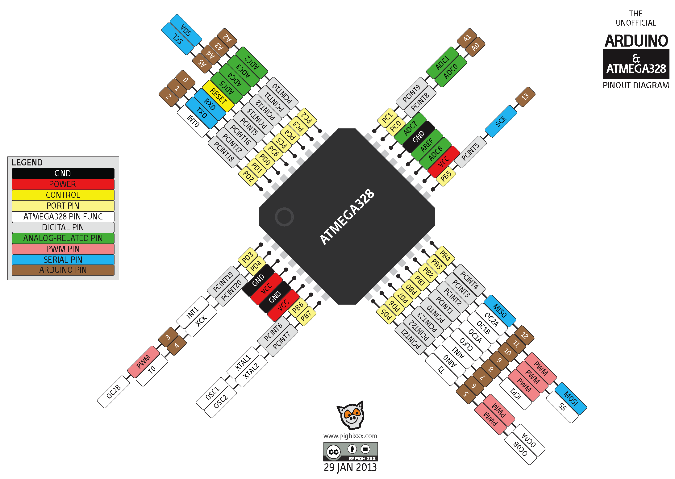
atmega328 pins for arduino :
I am anticipating issues as I've 1 ) switched out the attiny for the atmega, and 2 ) using arduino as ide. One of my first questions was, how do I call the pins that are attached to the copper sheets?
I've attached them to Pin 23 (A0) and 24 (A1). Honestly, I should have known better, and read through the atmega pin out... Not all pins are equal, duh. Well, I think I actually got lucky because this pin seems to be both analog / digital, which is what I need, right?
The search bar for isthe class also super helpful. After looking up "step reponse arduino ide", I got a couple of student pages that were pointing me in similar directions!
In order to use arduino ide to recognize the copper sheets as an input it seems you have to install the CapacitiveSensor.h libraries.
well, this is the working code i have right now :
when I tried to upload the code to my board, it didn't work.. my programmer has been kind half-functioning... the usb connector does not always connect, so I think tomorrow i might just try to program on the ICE programmer in RPL... otherwise, I'll be at office hours!
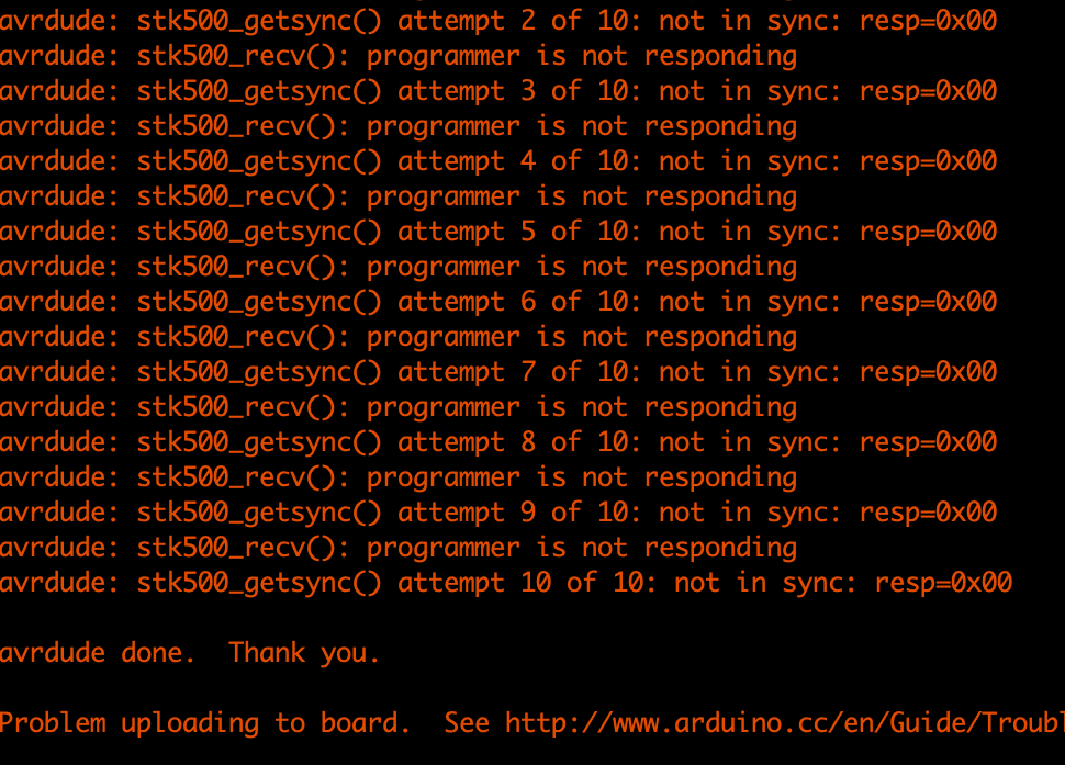
errrroooooors :
I spent four hours at office hours, about half the time w Anthony and the other half w Ben.
I spent four hours at office hours, about half the time w Anthony and the other half w Ben.
switching out the atmega328p :
Anthony rechecked everything I had earlier that day. Whether everything was connect / there were no shorts. Whether ground to vcc was 5 volts... etc etc. Finally, Anthony suggested switching out the atmega to see if that was faulty.
I really didn't want to do this because I had a hard time putting it on, but Anthony showed me how to properly use the heat gun and the copper braid, so it was actually super easy to remove and put back on. This was a big lesson I'm sure will benefit me in the future.
Anthony was out of ideas and suggested I speak to Ben.

adding an 8mhz xtal :
after about at least an hour with ben, he suggested adding a 8mhz xtal. when using the 328, you choose arduino as your processor but there are only two clock options 8 or 16, and ben was able to find out that my mega was working at 1mhz, so its highly likely the arduino ide was just not finding my mega because it was running at a slower clock. ben thought the easiest thing would be to add an xtal + 2 10 pf capacitors.
in order to get the correct footprints, i found and downloaded the part on snapeda.com. The part number was : ABM3-8.00MHZ-D2Y-T
I decided i would just remake the board. I actually ended up soldering TX to the wrong mega board input so I already had to do some surgery there, and i didnt really think trying to add three components via wire would be best...
new board:
thus we arrive back at the beginning - i went back to eagle and corrected the board (tx / rx issue and added the xtal + capacitors) - i plan to mill in the morning before class and hope to at least be able to upload my sketch even tho it probably has its own problems!
in the meantime, my pedal is printing! so that will be ready by the time i get this working.
old board:
corrected board:
I came in early to mill and solder my board to see if adding the crystal would solve my problem. Milling and soldering went pretty smoothly (though now after seeing the EECS soldering set up, I kind of think we are lacking in our tools).
When I went to program in Arduino - it did not work, again. I don't know what to do anymore!! I honestly don't know if its the board, the programmer, or the IDE. I am probably going to seek out a TA for assistance. I mean the goal was to avoid software serial, but at this point I'm wondering if software serial is that bad?
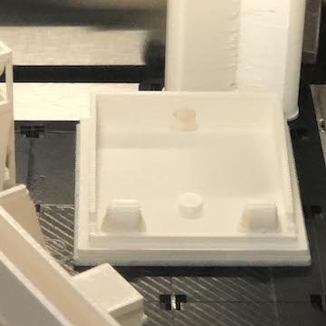
pedal printed :

pedal printed :
Well, my pedal was printed last night, but now has to soak in acid bath.
I hope I can get this board to work so I can incorporate it into the pedal....
Update : if you refer to WEEK 10, you will see that I was able to successfully add a button to my fabduino.
Here is a video of that small success :
Well, my pedal was printed last night, but now has to soak in acid bath.
I hope I can get this board to work so I can incorporate it into the pedal....
Update : if you refer to WEEK 10, you will see that I was able to successfully add a button to my fabduino.
Here is a video of that small success :