making
a "fabduino" :
a "fabduino" :
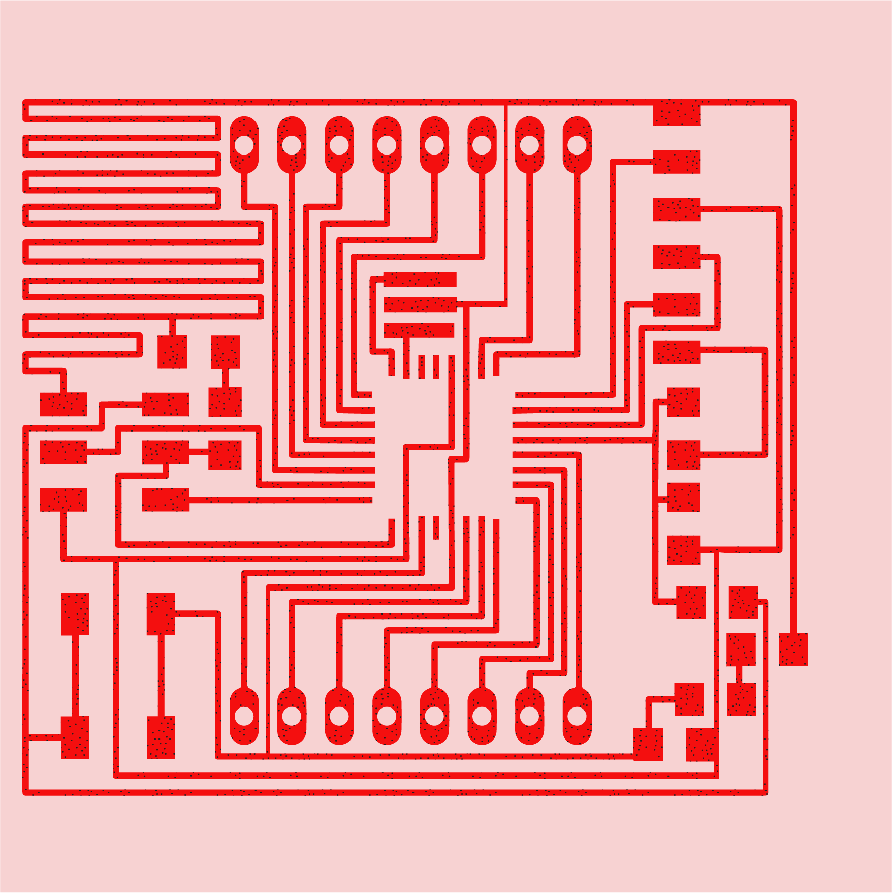
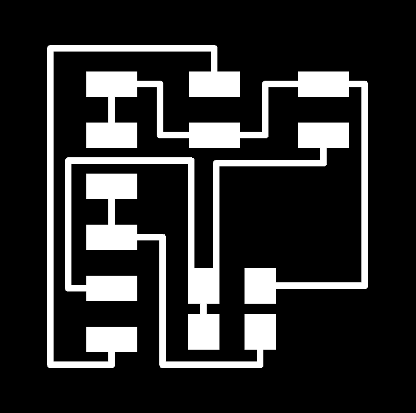
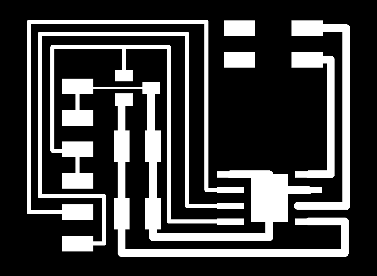
fabduino traces :
NOTE : I used WEEK 07 to make my board do something to make my board move a motor. Please refer to that week, and my FINAL PROJECT page to see my motor assembly. OR look at this week to hopefully see me attempt to combine input and output devices via a fabduino!
NOTE : I used WEEK 07 to make my board do something to make my board move a motor. Please refer to that week, and my FINAL PROJECT page to see my motor assembly. OR look at this week to hopefully see me attempt to combine input and output devices via a fabduino!
working final project motor assembly prototype :
Last week was incredibly disappointing :
In an attempt to slightly change the step-response board, I was unable to program my board to do anything. it seems changing the attiny45 to the atmega328was not as simple as I thought it would be.
To be clear, I now understand that I could have kept the attiny45 and not used software serial but used Neil's code. I understand that I can use Neil's code in the Arduino IDE, but I do not want to use Neil's code because while I do more or less understand it when parsing through it slowly, but I know that after the class I will not be using that workflow and so while Arduino in its various forms is not as efficient, I want to pursue it because I do think I will be using that on my own after this class concludes - in fact I would like to very much continue to do projects in Arduino. This is ultimately why I changed the attiny to the atmega. *Writing this out, I realize it's not completely logical - my apologies!*
After speaking to numerous TAs it seemed the problem lied in arduino IDE not being able to clearly identify the processor and what clock it was using. There are no preset boards (that I could find that also worked) for a "naked" atmega chip. Even when I added an 8MHz clock, the board refused to be programmed even though there is a preset board option for that in Arduino IDE. *update : it turns out the atmel ice on my mac osx was also an issue in not allowing me to program my board via arduino ide - see more below*
Finally Diego suggested making a fabduino, he said it was a turning for him when he took the class in 2014. From my understanding, an fabduino / diy arduino would allow you to easily, quickly, flexible interchange parts - inputs and outputs, vs necessarily making brand new boards designed to do very specific things...
So, having said that, I hoped that my fabduino would allow me to correct my failed step-response from last week and then I would try to hook up the motor I got working in WEEK 07. Maybe I could even control the motor with the input via just one board - the arduino.

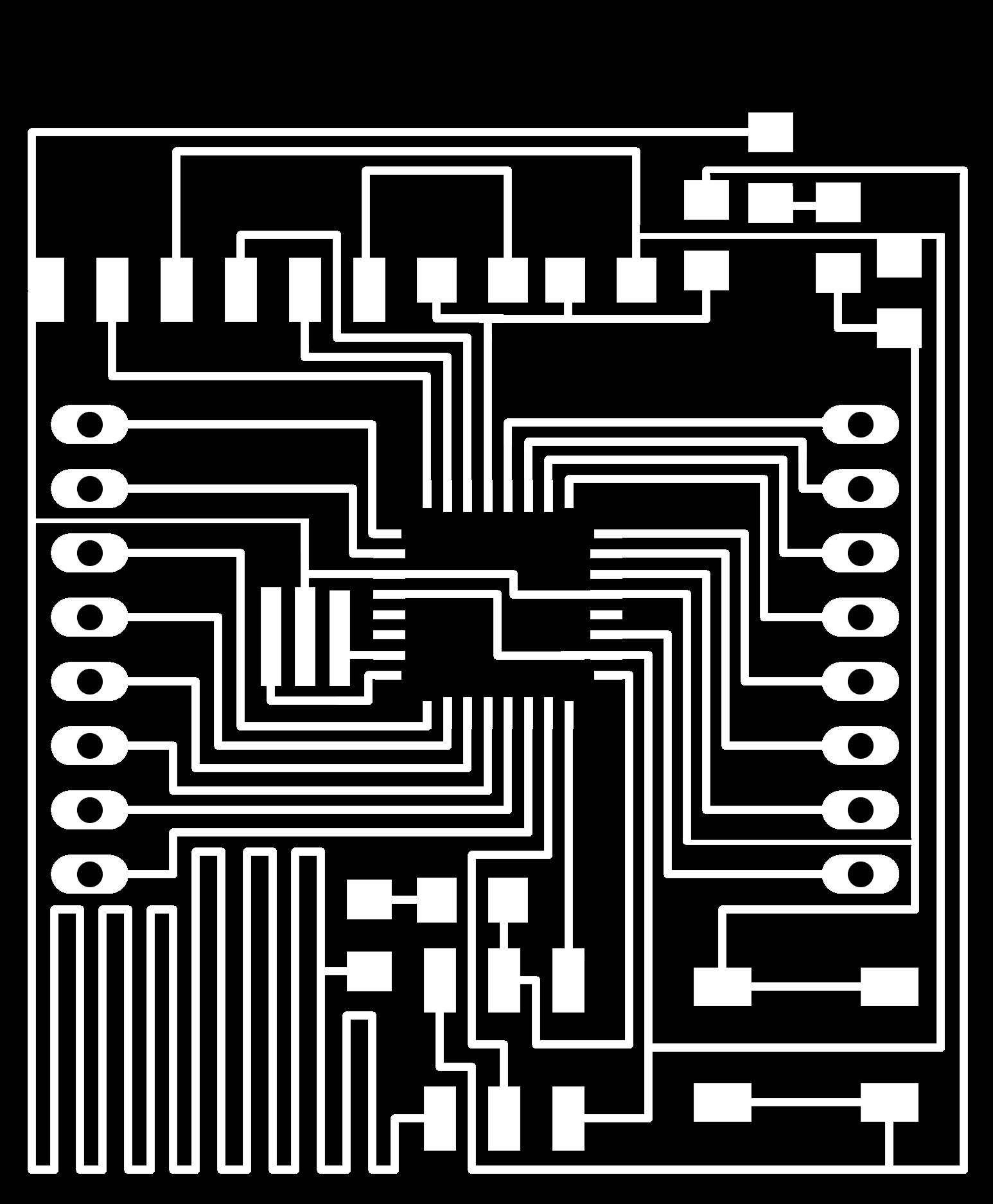
neil's arduino board :
I didn't remember / realize, but Neil had an arduino board too - found on the embedded programming week's page.
I didn't remember / realize, but Neil had an arduino board too - found on the embedded programming week's page.
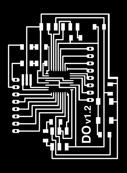
diego's arduino board :
Diego also pointed me to HIS BOARD he had made in the past - which I believe was based on Neil's board, but extended empty pins to be easily accessible.
Diego also pointed me to HIS BOARD he had made in the past - which I believe was based on Neil's board, but extended empty pins to be easily accessible.
my arduino board :
I more or less copied Diego's board. I was interested in extending the pins in order to make use of as many pins as possible.
this board was fun to make because it was the first time i used 0 ohm resistors to jump across traces and the first time i would drill holes into the board.
I more or less copied Diego's board. I was interested in extending the pins in order to make use of as many pins as possible.
this board was fun to make because it was the first time i used 0 ohm resistors to jump across traces and the first time i would drill holes into the board.
unsoldered atmega:
i was not looking forward to soldering the atmega, but after soldering two in the past week, i had learned a thing or two.
i was not looking forward to soldering the atmega, but after soldering two in the past week, i had learned a thing or two.
prepping traces w solder :
I found it was best to apply solder to the traces and remove as much as possible with the copper braid. For some reason this makes it easier for the chip to stick.
I found it was best to apply solder to the traces and remove as much as possible with the copper braid. For some reason this makes it easier for the chip to stick.

prepping traces w solder :
You solder one corner and then another and you still have a bit of give so you can still adjust the chip as you solder the second corner. If you're really careful, you can actusally solder the legs without creating bridges, but it is super easy to get rid of them w the braiding if you do. here you can see there is a tiny bridge on the top right corner.
You solder one corner and then another and you still have a bit of give so you can still adjust the chip as you solder the second corner. If you're really careful, you can actusally solder the legs without creating bridges, but it is super easy to get rid of them w the braiding if you do. here you can see there is a tiny bridge on the top right corner.
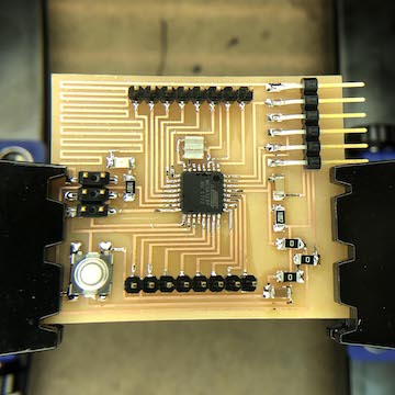
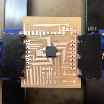
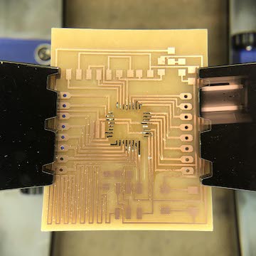
finished traces :
I actually was able to mill, solder, and (attempt to) program my board in under 4 hours! Which was kind of crazy! I wanted to do this before leaving for the long weekend, but alas I was NOT able to program my board. I was starting to feel like I was cursed or something. I had at this point milled three boards I was unable to program.
I actually was able to mill, solder, and (attempt to) program my board in under 4 hours! Which was kind of crazy! I wanted to do this before leaving for the long weekend, but alas I was NOT able to program my board. I was starting to feel like I was cursed or something. I had at this point milled three boards I was unable to program.
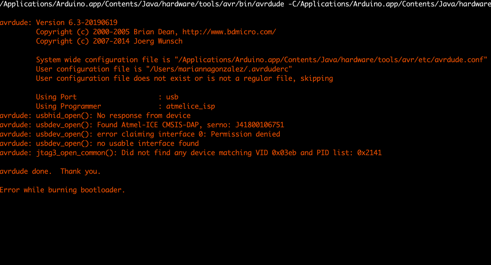
errorrrrr:
I tried multiple different things but I ultimately continued getting this message when I attempted to burn the booloader as an Arduino Uno, which is what I thought I should be doing.
I tried multiple different things but I ultimately continued getting this message when I attempted to burn the booloader as an Arduino Uno, which is what I thought I should be doing.
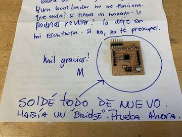
help me (!!!) note:
in my dispair i left a note w my board on diego's desk (we conveniently sit in the same studio space), hoping something would jump out at him that i had missed or that i was skipping a step.
It seems the problem was that I had not looked closely enough and left a bridge in between pins!
When I tried to run the burn bootloader on my own computer, I had many issues. Diego pointed me to make sure to add the fabkit, shown HERE under "Step Five".
But then I ran into issues because my Atmel ICE was not being recognized by my Max OX via this error :
Anthony pointed me to THIS WEBSITE in order to try to fix that.
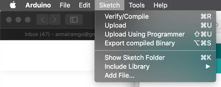
upload using programmer:
The bootloader finally ran, though it did have an error. It was enough to then be able to upload a sketch, but I still was not able to upload a sketch as one normally would, but after going through the debugging steps on the previous link, I was able to upload sketches via "Upload Using Programmer".
At this point, I'm a bit behind, but my intention is to try to hook up an input and an output to the Arduino.
So, I guess the point of making the fabduino was to somewhat quickly and easily test things.. I will try to make an additive board for the step response, a button, and a motor that I hope to connect to the fabduino. I haven't had luck using the step response, but I was trying to use it as a kind of button for my conveyor's push pedal.
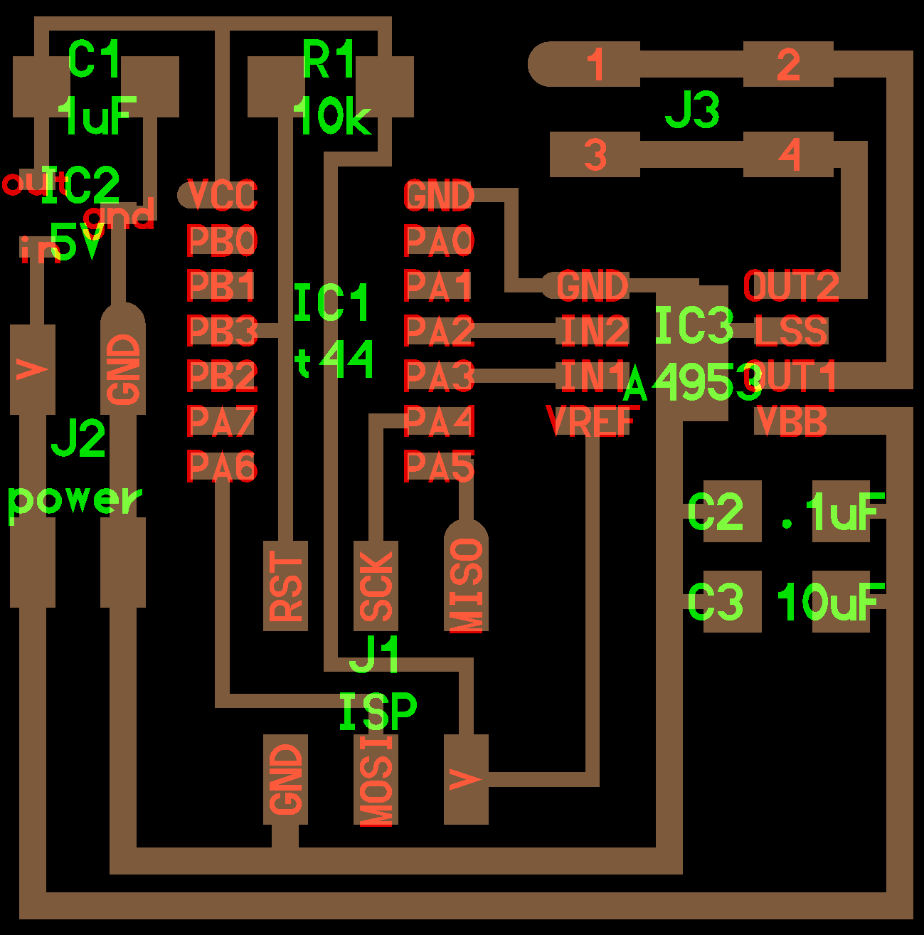
Here I basically took Neil's boards for a step response, a button, and a motor and made boards that would allow these components to be connected to their pin(s), ground, and vcc :
The bootloader finally ran, though it did have an error. It was enough to then be able to upload a sketch, but I still was not able to upload a sketch as one normally would, but after going through the debugging steps on the previous link, I was able to upload sketches via "Upload Using Programmer".
At this point, I'm a bit behind, but my intention is to try to hook up an input and an output to the Arduino.
So, I guess the point of making the fabduino was to somewhat quickly and easily test things.. I will try to make an additive board for the step response, a button, and a motor that I hope to connect to the fabduino. I haven't had luck using the step response, but I was trying to use it as a kind of button for my conveyor's push pedal.
Here I basically took Neil's boards for a step response, a button, and a motor and made boards that would allow these components to be connected to their pin(s), ground, and vcc :

neil's step response board:
step response board to be added to fabduino board:

neil's button board:

button board to be added to fabduino board:
neil's motor board:
motor board to be added to fabduino board:
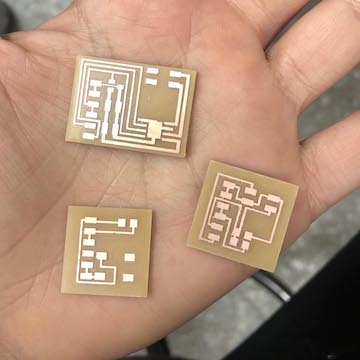
mini boards to be added to fabduino :
So, I guess the point of making the fabduino was to somewhat quickly and easily test things.. I will try to make an additive board for the step response, a button, and a motor that I hope to connect to the fabduino. I haven't had luck using the step response, but I was trying to use it as a kind of button for my conveyor's push pedal.
So, I guess the point of making the fabduino was to somewhat quickly and easily test things.. I will try to make an additive board for the step response, a button, and a motor that I hope to connect to the fabduino. I haven't had luck using the step response, but I was trying to use it as a kind of button for my conveyor's push pedal.

motor / sresponse / button boards soldered :

not working :( :
Unfortunately, when I hook everything up, the motor does not move... I was able to upload the code but nothing happens. Here is my code, taken from WEEK 07.
I did check to see there were no shorts. It seems the pins other than GND and VCC were not connecting to the fabduino. The solder was perfectly avoiding the headers inserted into the board. But once corrected, this still did not work.
I did upload Blink to the board successfully, so I feel like there is something wrong w the code or I'm plugging in things incorrectly... tbd.
In class, Neil noted that the 5v regulator will not work as it should if you do not add the capacitor. If you refer to my added motor board w neil's motor board, you'll see I failed to add it, so I'll try adding that to see if that changes anything.

arduino pin out :
I keep looking back at last week to refer to this diagram...
I keep looking back at last week to refer to this diagram...
button blinking working :
Though my motor board was not working, I was able to use my button board to control the LED on the fabduino.
When I tried to use the serial monitor, strangeness occurred :
Though my motor board was not working, I was able to use my button board to control the LED on the fabduino.
When I tried to use the serial monitor, strangeness occurred :
huh :
Although the characters seemed to indicate there was a recognition of when the button was on vs when it was off, I was getting weird characters vs 0 and 1s.
At office hours, Anthony said this was likely due to bad timing and when we reburnt bootloader with the breadboard internal 8mhz, the weirdness concluded!
Here is the code I used :
woohoo :
I thought this might solve my motor board, but alas it did not. I went ahead and checked whether there were any shorts and it seemed there were. I re-soldered where needed and plugged everything in and tada!
Finally, success.
I thought this might solve my motor board, but alas it did not. I went ahead and checked whether there were any shorts and it seemed there were. I re-soldered where needed and plugged everything in and tada!
Finally, success.
motor working w fabduino board :
The motor was acting strange though. While it would do a couple of turns, after a while it would stop and squeak unhappily, as if it was not able to turn but it didn't even move, it just made a very low squeak.
Turns out my battery is deaaaad! I'm so happy that is the problem here. The code I used is the same code w updated pins from WEEK 07.
Next stop : making the button control the motor:
In order to make the button control the motor, I basically combined the blink and motor sketch. I had a lot of trouble for whatever reason. While my board had been working earlier to stop and start the motor, it no longer worked. So I desoldered and re-soldered things. At some point the additive motor board causing the wheel to go without even being connected to the main fabduino, so I'm not sure but something must have been connected or not that was allowing the battery power to reach the motor as if the battery alone was hooked up to it.
button controlling the motor :
I'm not sure what I did, but at some point the button / motor worked! I was pretty happy. It seems like this was two weeks in the making! I think I might add another button that allows the motor to go in the opposite direction.
Here is the code I used :
And now I do want to try to make either a really nice button that allows you to go in either direction or a really nice pedal that goes in one direction and a button that allows you to go in the other direction.
More on that hopefully soon in the tracking page.
For now, I've successfully been able to add an input / output to the fabduino!!!