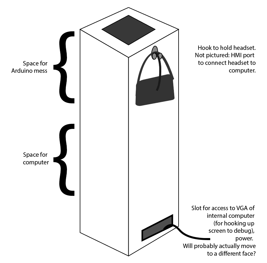
This week, in additional to... several other components... I'm making the board for my final project. The design has changed very little since week 1:
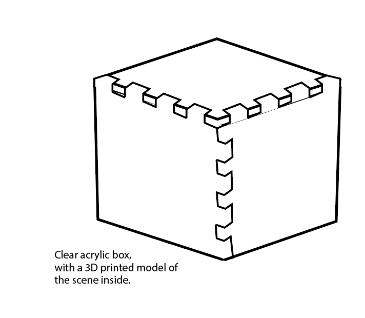
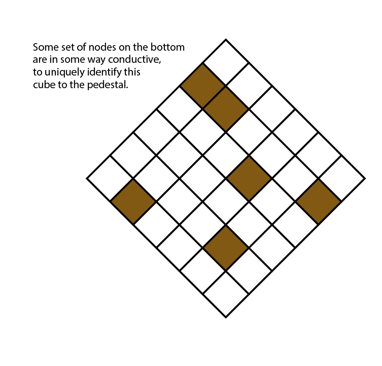
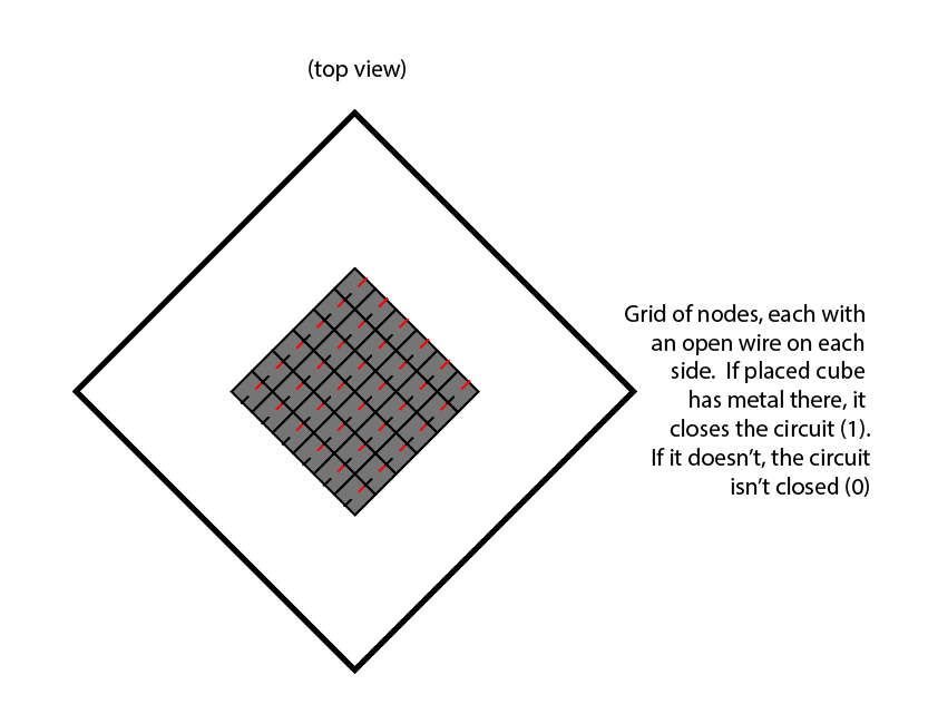
What has changed about it is that I've more or less figured out how to do it. When I talked to Jake about it a month ago, he helped me work out a way to use only 9 GPIO pins to get the effect I'm looking for, by connecting my whole "sensor" (which, to be clear, senses if the data and power pins are connected by copper on the bottom of the cube) to VCC, and then checking if VCC and any given GPIO pin are being connected by checking if the pin is high. It seems to be, in terms of embedded programming, not much harder than what I've already done in weeks 5 and 7. Then I can do the rest of the programming in Unity, which is my comfortable home language.
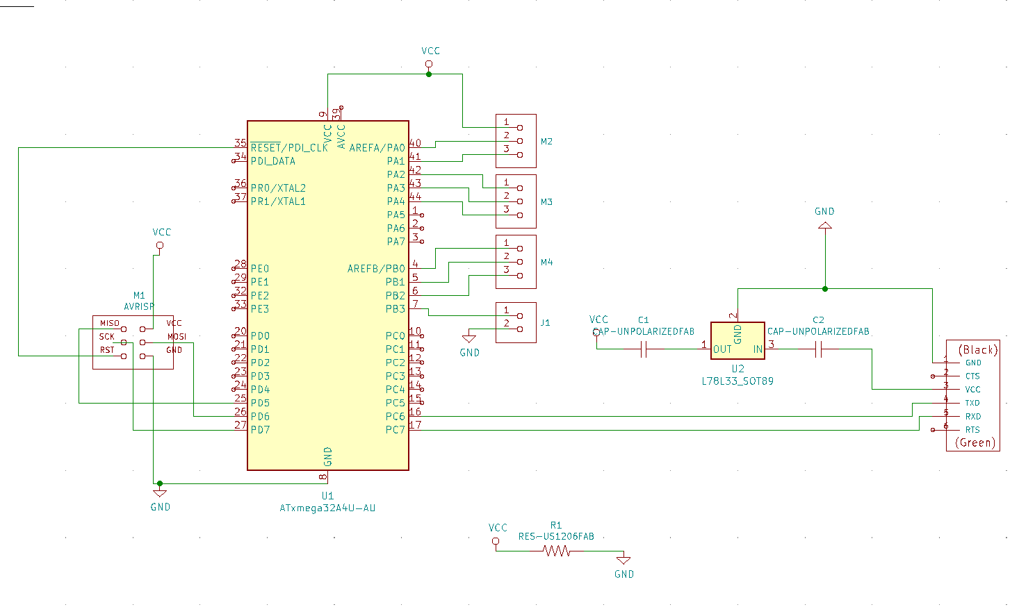
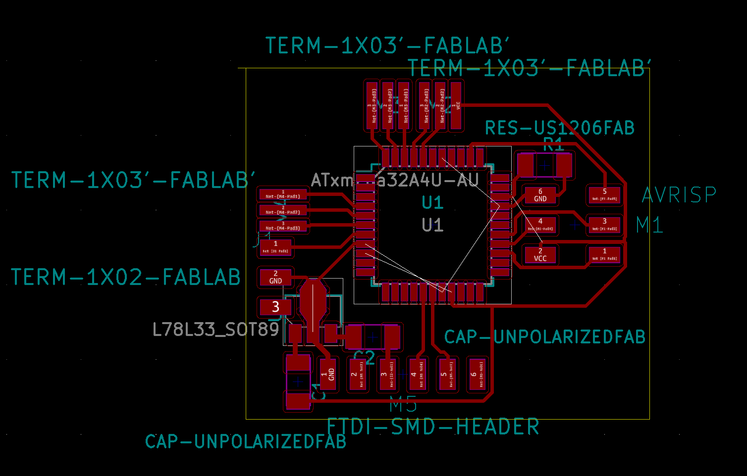
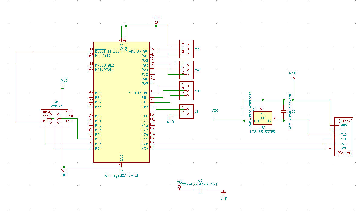
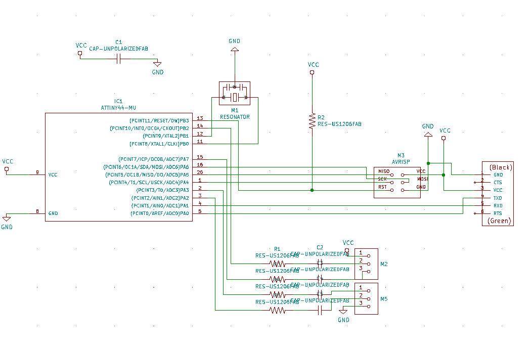
Jake also recommended that I use the ATxmega32A4U. I found this other project which also uses the ATxmega32A4U , and borrowed heavily from it's board design. This was my first, but not final, round of schematics and traces:
This time, before making a board that may or may not work over and over again with small changes until maybe I find all of the problems. I asked Zach to take a look at it. He suggested that:
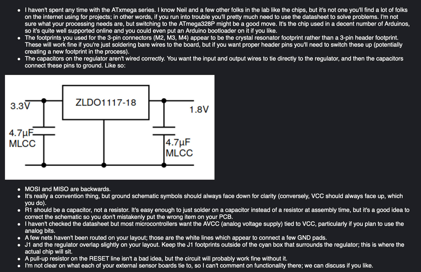
I fixed what of those changes I really understood.
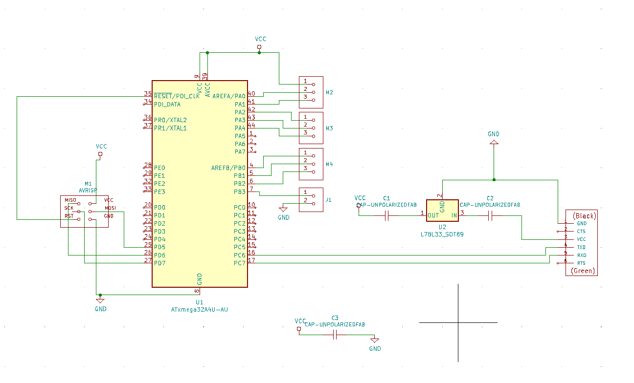
Then, I sent the board to Jake to take a look at.
Jake noted that there were still some problems with my bypass capacitors, and that there were some issues with Thresyvoulos's design related to pin outs-- his might use a slightly different or older configuration of this board? He shared an updated example of working with this board .
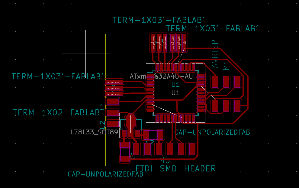
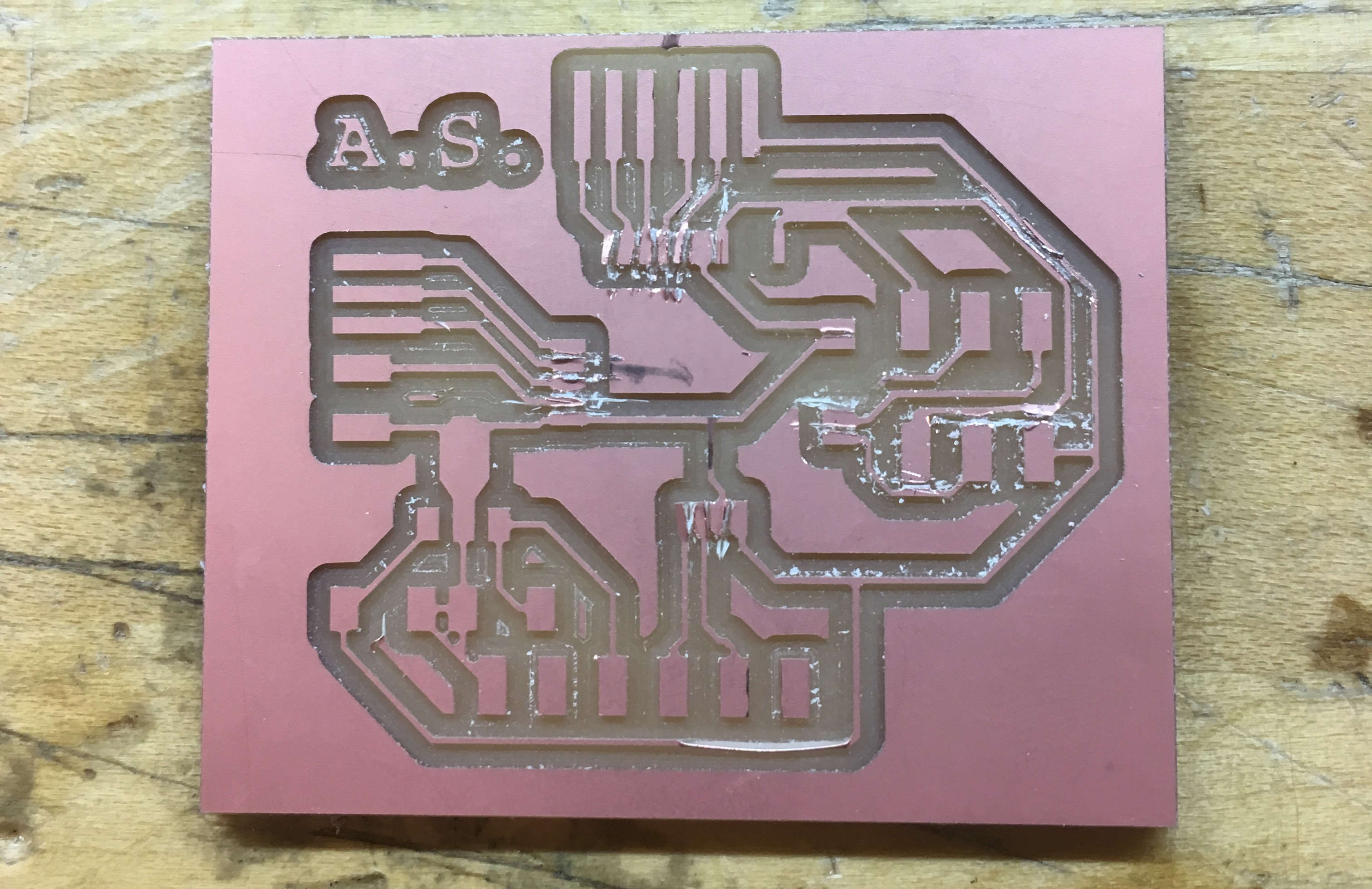
After one last round of fixing the bypass capacitors, these are the first round of traces to be tried out:
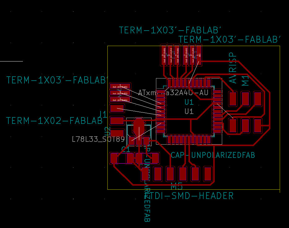
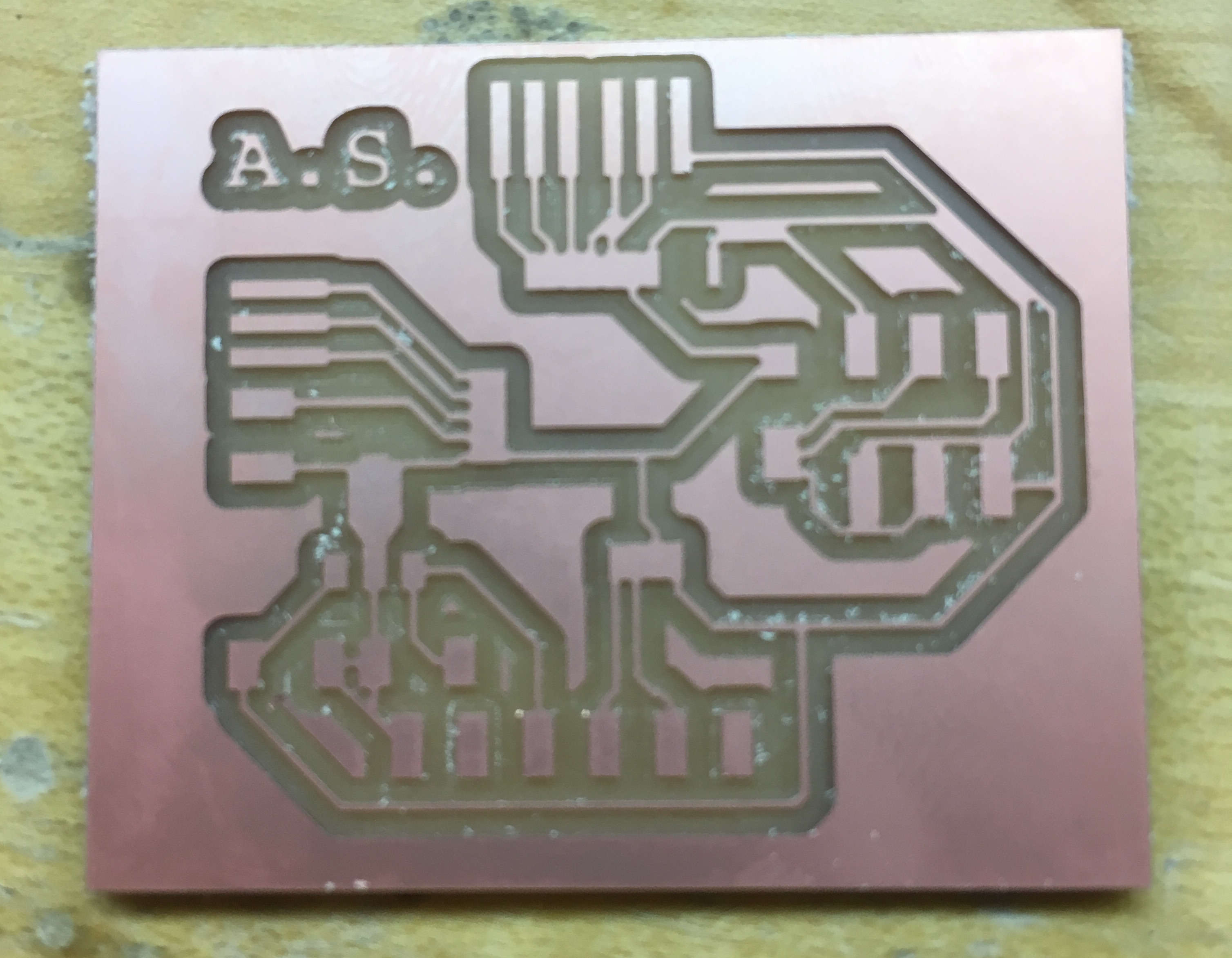
I very quickly learned that a 1/64" endmill cannot mill the pads of an ATmega-- they're just too small. I therefore tried to mill these details with a 0.01" endmill, and broke it almost immediately. Finally, I tried to mill what I could of the board using the 1/64" endmill, and then fixing the details by hand. It went exactly as well as you would expect.
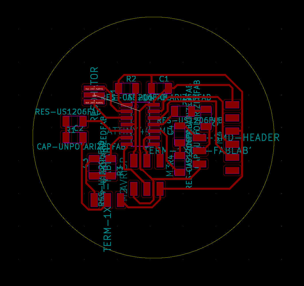
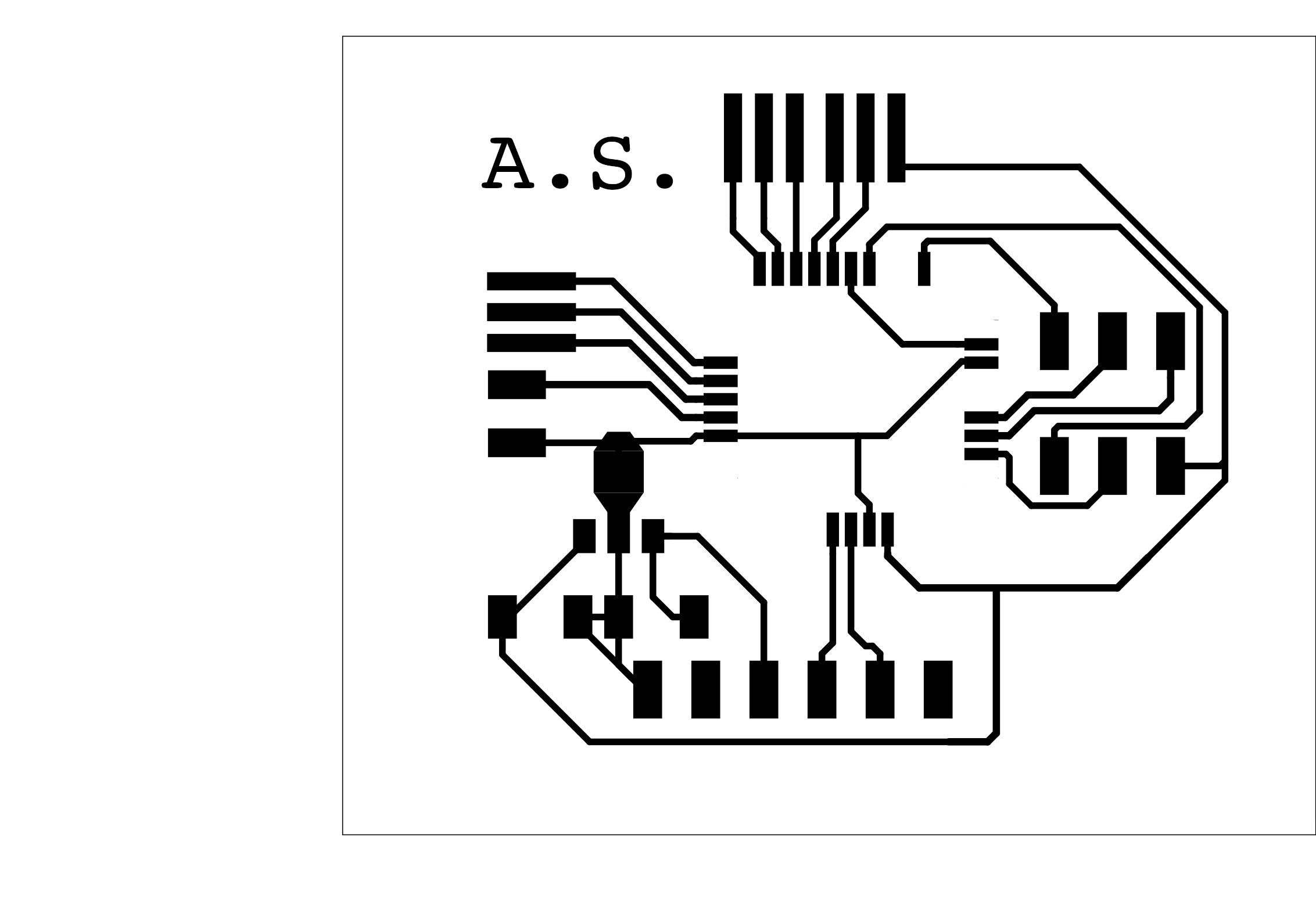
At this point, I decided that I do not like ATMEGAs. The most complex board I've ever gotten to work is the hello-echo board from week 5 (or, for me, week 11). I decided to make some modifications to my hello-echo board. Using every pin, it should be able to read 4 pins. That's 24 total different cubes, rather than the 362880 options available to me with 9 pins, but it is now Saturday, and 24 is plenty for a class project. I decided to add an LED to each pin, for debugging purposes.
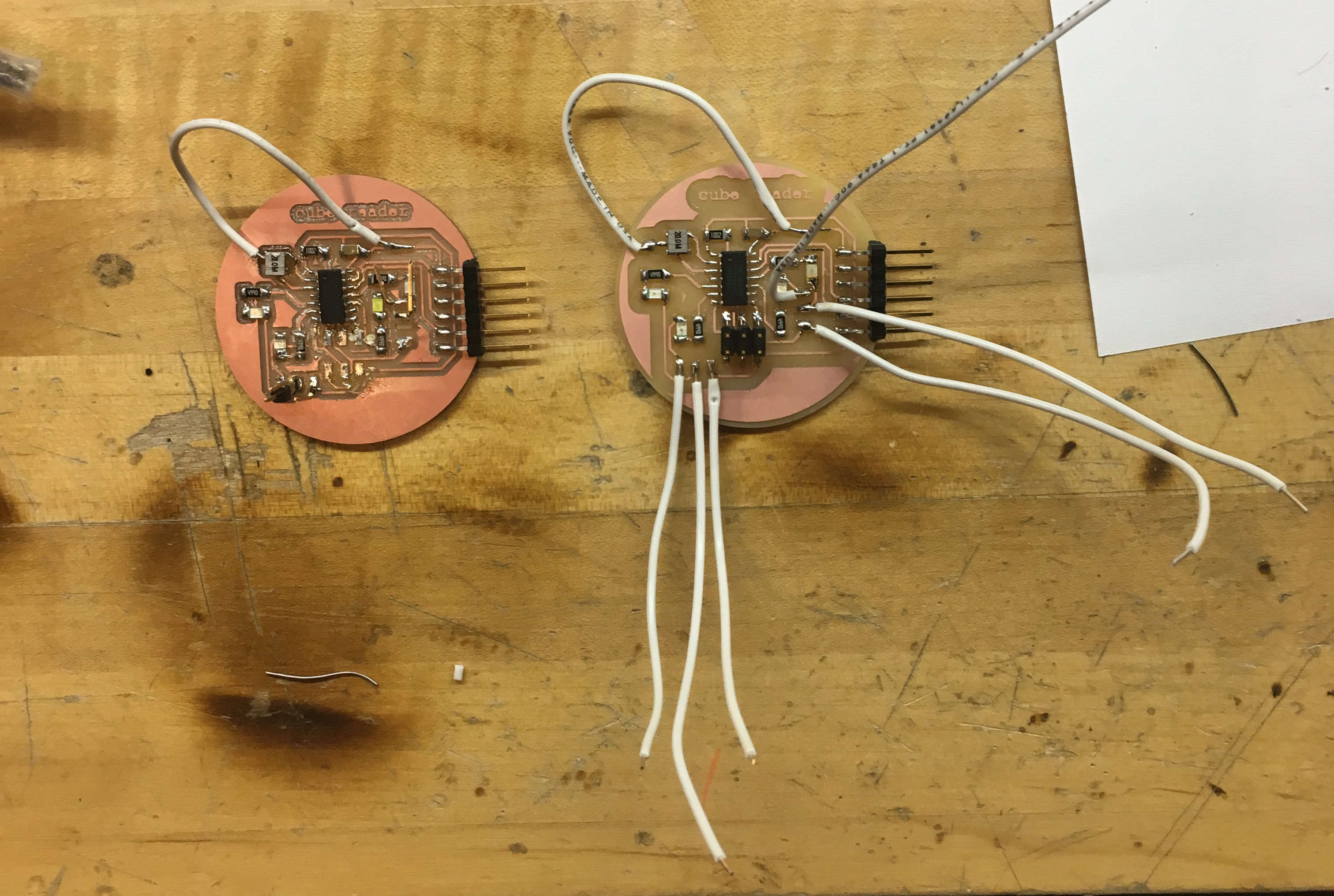
All of the LEDs on the board light up the way they should.
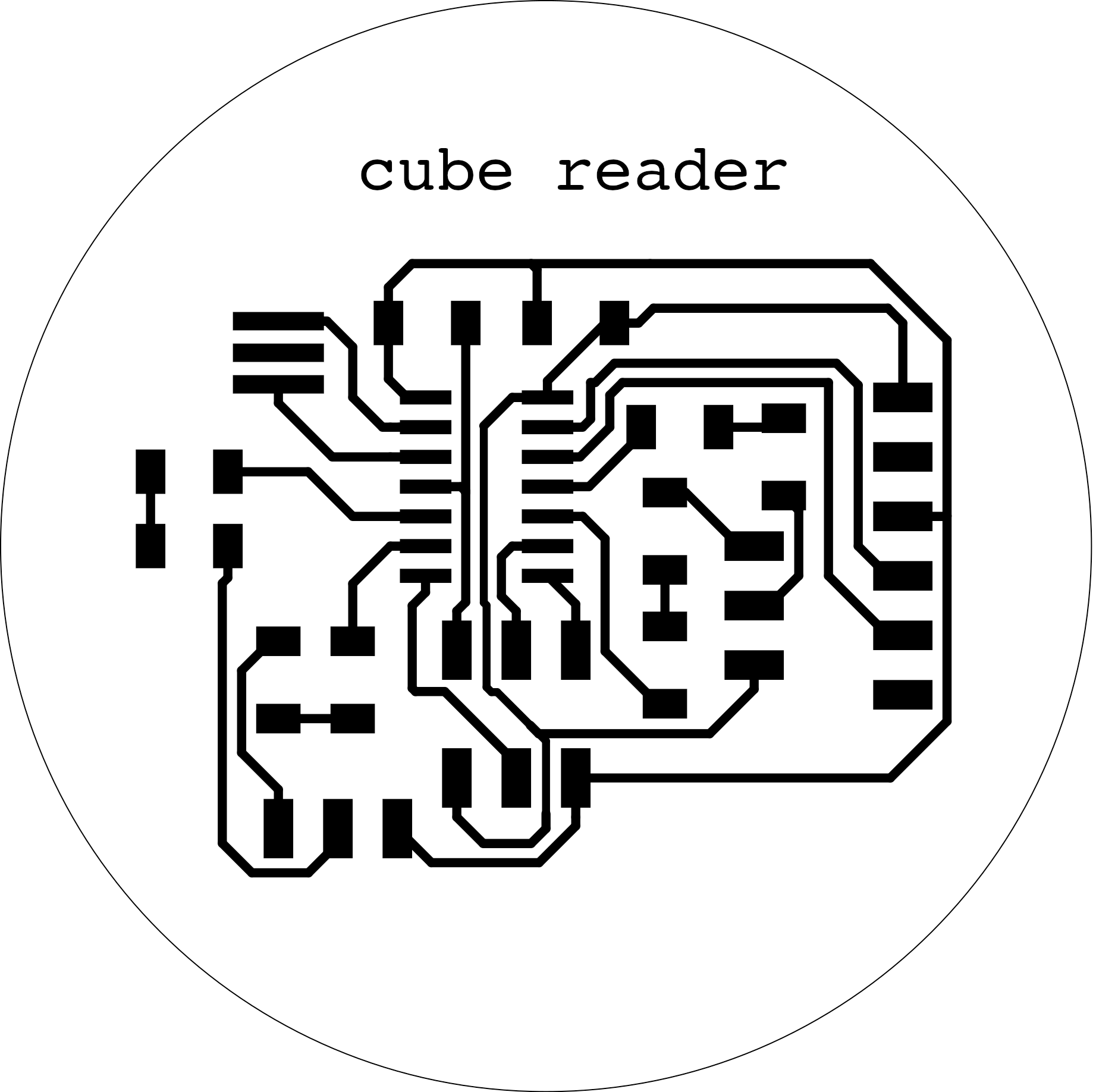
`Note the unconnected net between the resonator and ground anywhere else on the board. "That looks hard to route." I said. "I'll just connect it with a jumper. That will be fine."
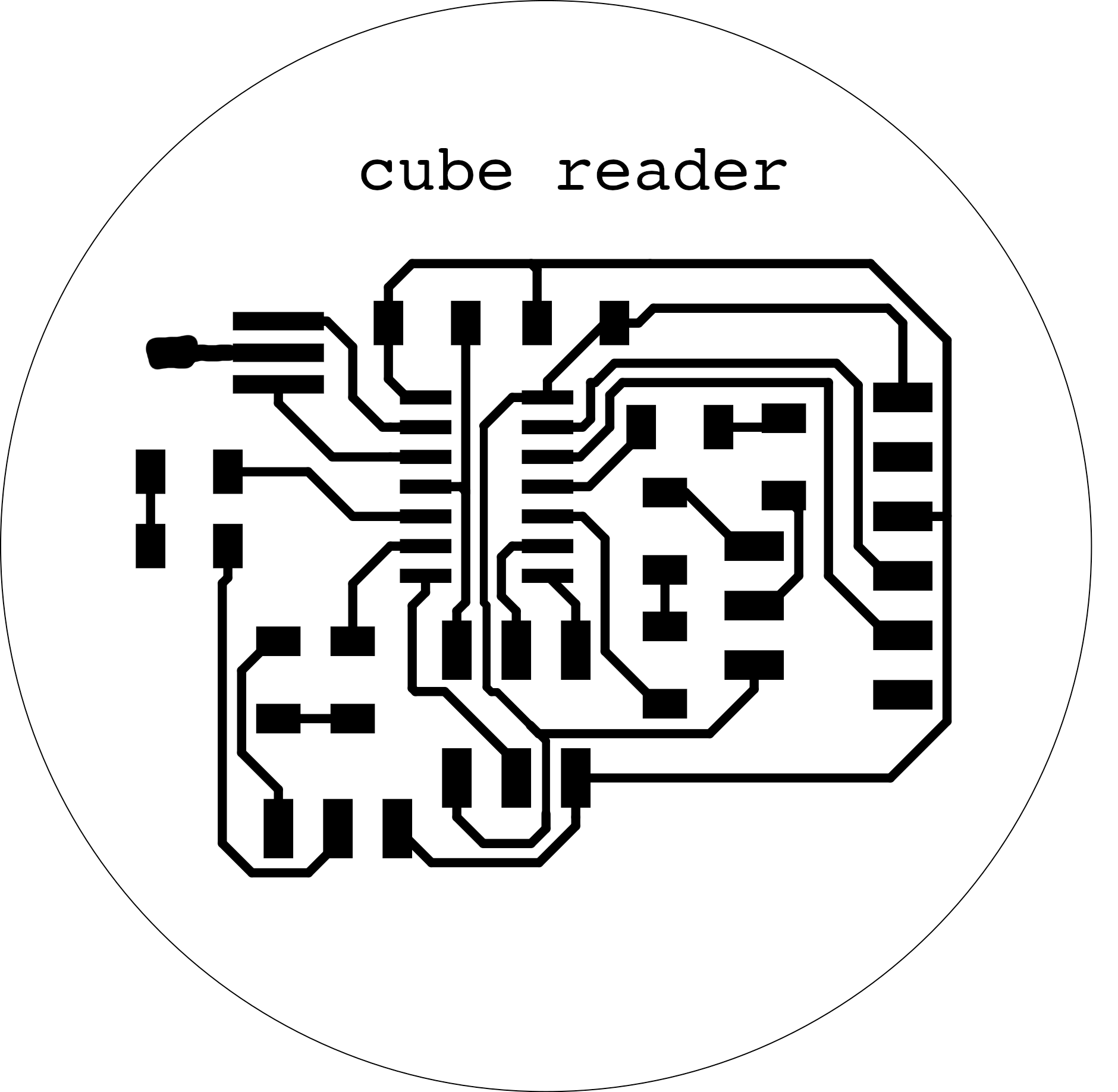
After several hours of being confused as to why my board would not program, I realized that I had forgotten to solder this jumper. While soldering in the jumper, I learned that you can't really sandwich a wire in between the ground pin of a resonator and the board-- it's just too hard to solder. So I went back to GIMP and drew in a pad for it.
This version also didn't work. I was fairly certain it was because there are two pins that just barely touch under the AVRISP header. Now that the header was soldered on, I would have to take it off in order to fix it. I managed to rip the traces up in the process, and so it was time to mill the board a third time, but this one successfully took my week 7 code.
Difficulties with programming the board are why this project was not finished. I'm pretty proud of the c code that I wrote, and fairly certain at this point that it would have worked.
The code is supposed to send either a 0 or a 1, for each of the four sensors. Easy, right? Not at all. After more than 10 straight hours of what should be an easy problem, while I did not obtain the state of the code working correctly, I did attain all of these other states:
my actual final project is a poltergeist
These states were caused by:
So, that's it, I guess. The whole final project doesn't work if this part doesn't work. It's Tuesday morning. This part doesn't work. If you're reading this, in the future, and you understand what went wrong with this code, please email me.