Weekly Assignment Contributions to Final Project
- Input Week: Detecting catches with the ADXL343
- Output Week: Driving color LEDs
- Networking Week: Bluetooth communication with the ESP32-WROOM-32
- Interface Week: Juggling Simulation and Web Bluetooth communication
- Wildcard Week: Robot Arm Juggle
Planning and Development/Iteration
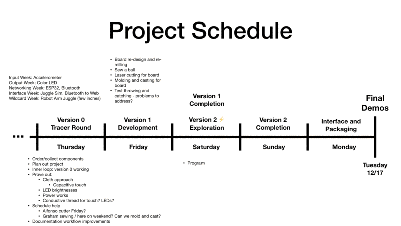
I started out the final project push by putting together a project schedule:
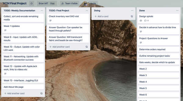
Used Trello to outline my remaining tasks:
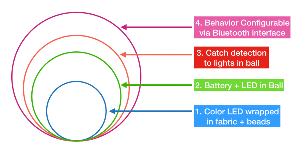
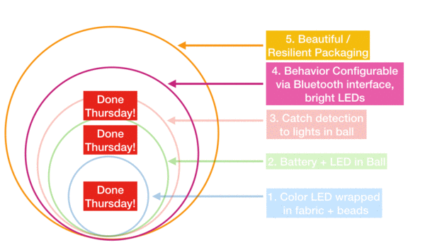
Developed a series of spirals to aim for:
Ordering and Collecting Components
On Thursday morning, I visited Micro Center to determine which of the remaining components I needed to collect were there. To my surprise, they had quite a wide selection of items.
I found a 2000mAh Lithium Ion battery that was small enough to fit within a 3-4 inch juggling ball, and would likely provide more than enough power to the board for long enough to last an entire demo day.
Testing ESP32 Long Term running
I ran the ESP32-WROOM32 attached to my USB cell phone charger brick and it ran successfully while cycling the RGB LED color for 4 hours. It ran without any issues, and didn't heat up at all.
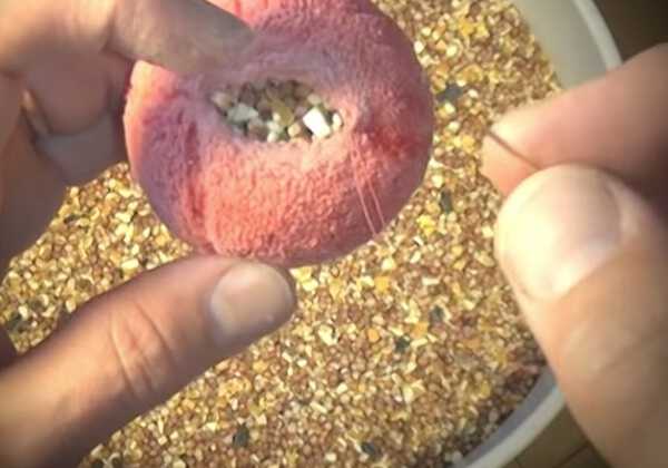
Testing Translucent Beads and Fabric
Pouring beads into a plastic bag:
With one RGB LED in the light:
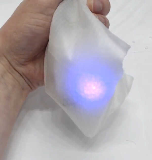
With one RGB LED in the dark:
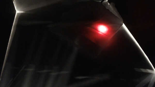
The board held up surprisingly well for being encased in a bunch of beads. Even the bridge wires seem to have survived.
To see if it would stay on, I got a rubber band and tried throwing the bag:
One surprising thing I'm finding is that the beads are very slippery. A negative is that they likely can't be relied on for positioning things within the bags. A positive is that they will allow for easy inserting/moving components around in the bags.
Capacitive Touch via Thread
One thing that excited me about using a fabric-based ball enclosure is that it would enable using capacitive touch as an input mechanism. I haven't seen this done on other juggling balls before (and maybe for good reason!)
The ESP32-WROOM-32 has built-in capacitive touch pins:
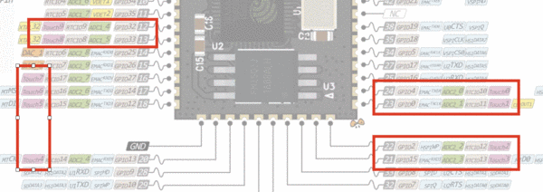
So I tried hooking up to them. When I first heard about the conductive thread, for some reason I assumed you could just solder it to pads. Wrong! This is why the lilypad and other sewable Arduinos tend to have pads with cutout circles in them.
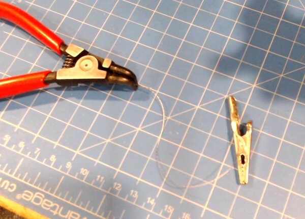
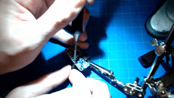
Just to prototype whether this approach might work, I used a metallic intermediate connector to go from the ESP32 pin to a soldered wire to an alligator clip to the thread and then tested touching it.
The pad-soldered wire required a bit of babying since it was free-standing. Holding up the thread would have caused the
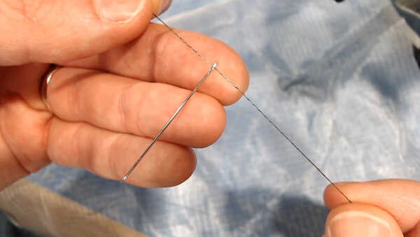
So I took a pair of pliers with insulated handles, held up the thread, and tried touching the thread:
Success! This approach may work. The next step is to see whether a weighted bean bag with thread sewn throughout it would trigger a noticeable cap touch change.
But... I've never sewn before.
Capacitive Touch via Fabric
I tried sewing for the first time. Not bad! Just went up and down a bunch, and then tried to tie a knot. The final knot was hard! I'll have to ask Graham how to do this properly during Friday's introduction to sewing.
Capacitive Touch via Fabric to Color
Just to get an end to end input to output going, I decided to use the cap touch value to drive the color LED.
The range is typically 70 (fabric test) or 40 (pliers test) down to 14-15 when an extreme grab occurs. So I want to do something significant when 15 is hit.
I decided to try modulating the LED brightness by the cap touch value.
hueToRGB(color, max(0, min(255, touchRead(T3) - 15)));
Success!
Power Supply
Now I want to see if the Adafruit 2000mAh Lithium Ion Battery I have will work for these balls.
I'm trying manually hooking up the Adafruit PowerBoost 500mA Lipo Charger. This is a bit expensive ($15/per), but will let me hit a baseline and gives USB charging for free. A SMD JST might be better / cheaper later.
I used a couple of carefully placed aligator clips and it worked!
Weirdly I got a real big static shock when I touched my laptop after pressing on stuff.
v0 - All Together Now!
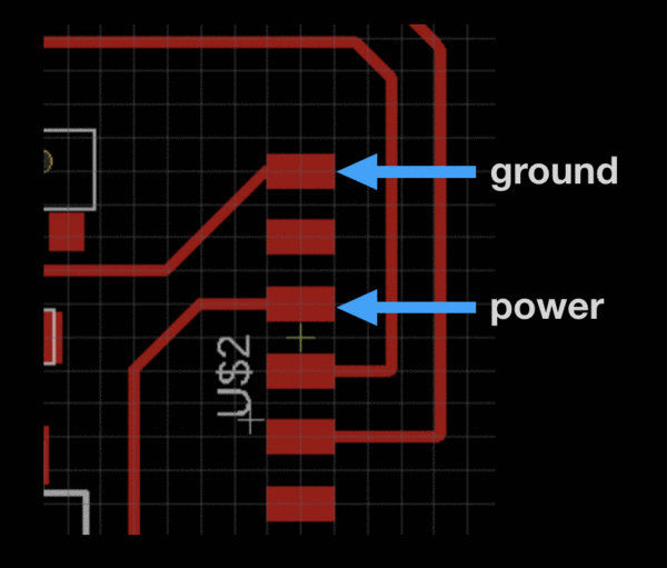
First I want to get the power connected well enough so it won't definitely fall off / short. I found some M/F jumper cables I could use to go from my FTDI header power/ground to the power board.
I soldered the M part of the cable into the holes in the PowerBoost for +5v and GND.
It worked! And everything is so self-contained!
If I'm going to continue using the PowerBoost, I'll need to do something about that pesky blue-light-while-on! It makes it really hard to see our single, less powerful LED.
Success on the first few loop goals of the ball:
I'm going to test leaving the whole thing connected and assembled overnight (with me) and see how long it lasts.
Overnight Test
The ball stayed lit and running overnight! (Update: it lasted about 18 hours.) The 2000mAh battery is probably overkill, but if I can program it wirelessly (which is apparently possible with the ESP32, this may make it easier to iterate later on.
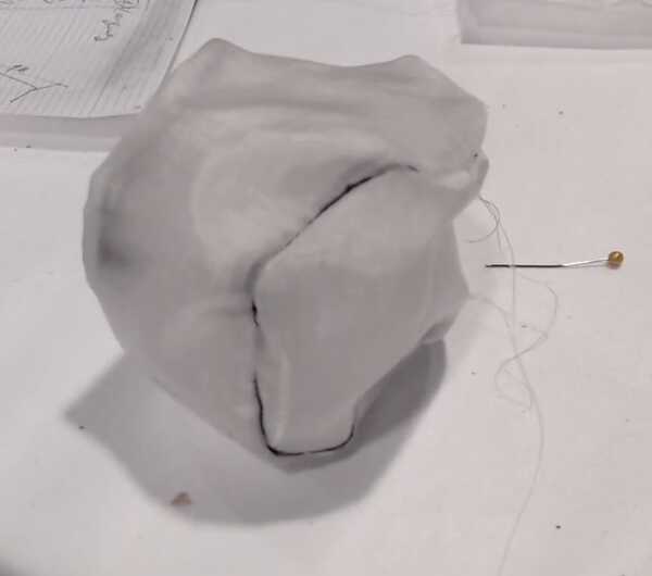
Sewing Test
Today I am learning to sew with Graham with the goal of creating a nice package for the ball.
I'm starting out by doing by doing some research into how juggling balls can be sewn, what patterns are required, etc.
One approach is a 4-panel juggling ball. It looks like 4 orange slices, and you sew them all edge to edge. It looks like it would be hard to do with much machine assistance.
Stuffing the ball seems to be done by leaving a small hole in the final connection (via Jeremy Shafer):
Since for my ball I will likely be keeping the pellets within a plastic baggy, I might need to do the whole final stitch (or maybe velcro?) at the way end.
Jeremy Shafer also has a guide for creating them and templates for a few sizes.
These patterns have up to 65mm. Someone online suggested they like the two-panel approach as it's the easiest to sew and "for not having any seams crossing", but "they tend a little more to become unround, cubic even, if sewn inaccurately."
The two-piece ball pattern has a postscript file you can modify. I notice it has a constant at the top that corresponds to the size of the ball. I will try modifying that to be closer to the 3.5 inches (99mm) I'd like to use.
It seems to have worked, but it gets cut off due to the orientation of the PS file. I'll need to figure out how to rotate it (inserting rotate 90 various places didn't seem to do it).
Sewing Tutorial with Graham
Graham was kind enough to introduce me to how to use the sewing machine. Threading the machine initially was complicated! Fortunately the guide on the Singer manual is a helpful reminder.
One tip: if you leave the needle in and the feet up, you can rotate around the needle:
Graham's attempt came out quite nice! We left a hole at the top to fill with Poly Pellets.
I filled the ball with Poly Pellets:
And weighed the result.
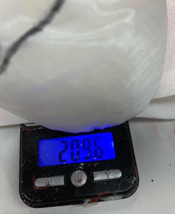
209.6g is 0.462lb, which is $1.53 worth of poly pellets.
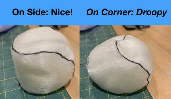
The ball feels really nice! The nylon and the pellets are slick, and the nylon is super thin so you can feel the pellets.
When stood up on a corner, it sort of droops like a parallelogram, losing a bit of its ball-like feeling:
Some open questions will be: how will the ball feel with electronics and plastic around everything? How will I fill and re-seal it? Will the lights shine through enough with this larger amount?
Sewing one on my own!
This weekend I will be continuing to create these balls, so want to take a stab at one while Graham is here.
I began by drawing lines to cut out two sides of the ball (later I may want to use a lighter marker).
Then I pinned up the cut out.
Sewing went OK for a little while! What I learned is I should leave more of a seam allowance (Graham suggested about a quarter of an inch.)
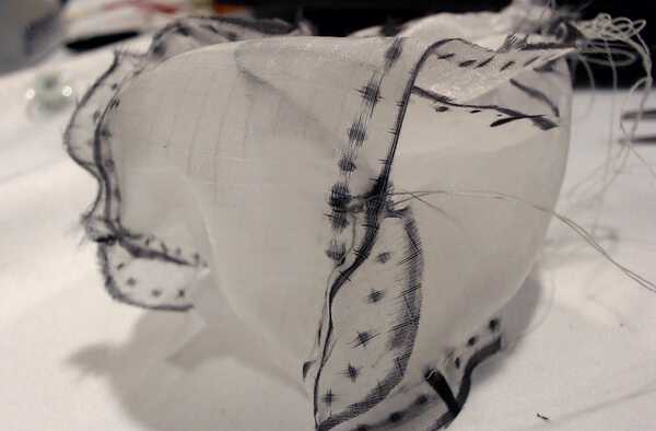
When I got too close to the edge, things started bunching up, and the ball started looking like the fabric version of Zalgo text.
This required un-jamming the sewing machine. That was mostly a process of cutting the threads, pulling things out, and re-threading everything. Graham helped with the bit of fabric that ended up inside of the lower part of the needle receptacle.
I used the seam ripper to remove the terrible part.
Did a bit more repair, and the ball was complete enough (just barely!) to hold pellets.
Light Exploration
I want to figure out what types (and geometry) of lights will be best within the balls.
I have a variety of lights I can test:
- Single RGB LED from the Fab Inventory. This is barely visible, and I suspect for day-glowing we'd want 8-10 per ball at least. Something like a lilypad sort of system might work, but a rig that keeps them oriented away from the middle of the ball would be ideal.
- Strip of LEDs from AliExpress - $21 for 60 LEDs
- 2 NeoPixel Ring 12 x 5050RGB (Micro Center) - $7.49 for 12 LEDs
- 1 NeoPixel Ring 16 x RGBW Cool LED (Micro Center) -
- 1 NeoPixel Jewel - 7 RGBW Natural LED (Micro Center)
- 1 NeoPixel Ring 24 - Natural LED (Micro Center)
It seems like for the most part they all use the same 5050 LEDs.
(Power-related note: I started re-charging around 8:15pm? The blue and orange lights turn on when I do that.
In thinking about how to test these lights on my board, I looked up how to deal with through-hole connections. This StackExchange guide had a bunch of nice photos.
Grabber test clips or alligator clips seem like good options. I couldn't find grabber test clips so I will use alligator clips and jumper wires.
Alternatively, I bet I could use conductive thread.
I ended up doing the following:
- Staple-shaped jumper cable on the NeoPixel ring, twisted around the inlet hole. Use that to get up out of the cup.
- Alligator clip from that to exposed wires I soldered in to the board.
- Using #define LED_PIN 25 in the Arduino sketch, which corresponds to the pin labeled GPIO25 in the ESP32-WROOM32 pinout.
I poured a bunch of the pellets into a translucent plastic cup, and shimmied the nylon fabric we're using to the outside of it to simulate how it will look.
The 16 LED ring lights up fantastically, and surprisingly you can't even tell from the outside which way the ring is pointing. I hope this means the beads are doing enough diffusion to get beyond the issue Jiri had mentioned some light up juggling balls had where two hemispheres of lights would cause a ring of un-even un-lit-ness on the outside.
Suddenly only 7 of the 16 pins were lighting up. Odd.
The 7 pin NeoPixel (RGBW) was quite nice and worked fine, but not quite enough power to hit a half-cup full of the beads.
There's a line Adafruit_NeoPixel strip(LED_COUNT, LED_PIN, NEO_RGBW); //NEO_GRBW + NEO_KHZ800); that controls the controller type for the LEDs. I will try just NEO_RGBW instead of NEO_GRBW which was the default.
Nothing happened when I changed it to NEO_RGBW, so trying going back to the combination -- nothing again.
The WROOM is starting to heat up a bit. I wonder if there is a short somewhere.
I guess it is GRBW not RGBW. Weird!
Nevermind - it turned out I had the wrong pin selected already.
With _JUST_ RGBW, it has a bit of a flicker when it lights up. With both NEO_RGBW + NEO_KHZ800 set, it is very smooth. The judder reminds me of when I had it hooked up to the capacitive touch test pin.
Testing the NeoPixel Ring 24 - originally I had the wrong setting for this and the cycle was very RGB-y. I switched from NEO_RGBW to NEO_RGB and it worked beautifully. Though I had to also up the # of LEDs!
Next I wanted to test the brightness difference. (Interesting to note, it seems like sometimes in the pattern the LEDs stutter when they should be off.)
Sewing: Round 2!
This morning I worked on sewing a conductive thread ball at my house with the assistance of my wonderful sewing expert mom!
I now have a ball shell that works well for experiments.
Some notes:
- We left a flap open so I could take the pellet and electronics assembly in and out.
- Capacitive touch was a bit finnicky but when zeroed in properly it worked great. I may want both accelerometer and capacitive touch for that reason.
- The one thing that goes from inside of the ball outward is conductive thread.
- My modified postscript file worked great.
Board Re-design
Now that I know what new features I'll need for this:
- Ability to connect two or three NeoPixel ring/strips to board (power, ground, out)
- Ability to connect accelerometer
- Ability to connect power (JST or special power board)
Ability to connect speaker to board
Speaker? Buzzer?
In doing some more research about driving speakers with the ESP32, I decided to ditch audio in favor of focusing on accelerometer, capacitive touch and lights.
Driving NeoPixels
Two big pieces of advice on the NeoPixel website:
- Adding a 300 to 500 Ohm resistor between your microcontroller's data pin and the data input on the first NeoPixel can help prevent voltage spikes that might otherwise damage your first pixel. Please add one between your micro and NeoPixels!
- NeoPixels take 5 volts (though it sounds like it can also survive with 3?)
- They want a 1000uF capacitor between + and - for these. Or just connect - first always?
I will look at adding 3 5v and 3 ground, and 3 output breakout pins. I will test that those output pins work for NeoPixels too.
Choosing NeoPixel pins
I quite like Pin 24 (Touch 0) for this. It is close to the outside of the board already. Unfortunately right now, though, that pin is not exposed to the outside because it is blocked by RX and TX.
RX and TX could go around the other side of the board, though.
Choosing Capacitive Touch pins
Eyal's board had a nice approach
Simple Power Supply - JST SMD
Eyal had 3 SMD JST pins. I will mount those down.
Re-designing board in EAGLE
I took a look at the Lilypad Fabduino for inspiration.
I love the idea of using a pad like this for cap touch pins.
I'm having fun making the board look cool!
Extra pinouts I will need:
- Capacitive Touch - I can connect via a housed cable with something like this
- NeoPixel 1 - GND
- NeoPixel 1 - +5v
- NeoPixel 1 - Input
- NeoPixel 2 - GND
- NeoPixel 2 - +5v
- NeoPixel 2 - Input
I realized what may be my pinch point may be accelerometers!
They all seem to require Vin, Gnd, SCL, SDA for i2c.
According to here:
The hardware I2C pins for the ESP32 are GPIO 22 (SCL) and GPIO 21 (SDA). The pins with a blue rectangle in the figure below.
Of the types I have:
LSM90S1: Vin, 3v3, GND, SCL, SDA
- can have 2 (one more at Microcenter tomorrow)MPU9250: XXX, VCC, GND, SCL, SDA, i1, SCL, SDA
- 3 comingBNO055: Vin, 3vo, GND, SDA, SCL, RST
MMA8451: Vin, GND, 3Vo, i2, i1, SCL, SDA
VIN == 5v, 3v == 3v
The LSM and MPU can be made to work together if you treat the MPU VCC as 3v3, since according to its Amazon description:
* Supply Voltage: 4.4 to 6.5 V or 3.3V if you solder the solder jumper near the on-board voltage regulator
So I could have 4 pin FTDI style header hanging off the side.
Which pins could work for the NeoPixels? Above I said 25 worked well, and I see that right now. But it's down at the bottom of the board.
Is it any GPIO? Let's try 4 and 16 since they are close to our pinout.
GPI04 (second to last) works well
GPI016 (third to last) barely works...
GPI017 (fourth to last) also barely works...
Maybe they need to be ADC?
Wonder if we can share the programming one (GPIO2)
How about 5. It works well! That will be close enough to where I need it.
Finally have my EAGLE board all designed! A few things of note:
- I used a circular design for the first time
- This is the first time my design rules worked from EAGLE to mods.
- v1 RGB-Accel.sch
- v1 RGB-Accel.brd
- Cutout
- Top
The milling and stuffing went well! I got in to a groove of stuffing as my next board was being milled.
"What is this mess? Oh it's a graphic!" -Eyal
v2: Final Assembly and Programming!
Yesterday I got all of my boards milled and together!
Today I am going to be programming the boards to have configurable lights and possibly start in on pattern generation. Tomorrow will be about getting the interface going.
I'm going to start out by testing capacitive touch driving the NeoPixel colors.
I originally picked the wrong pin!
I had set a #DEFINE TOUCH_PIN but not used the variable when I called touchRead(TOUCH_PIN)
It works! Some things of note:
- When plugged in to my laptop, the tuning for what constitutes a capacitive touch changes. It will be helpful to have an internet connection in order to debug what's going on on the board
- When turning the LEDs off, sometimes one random lone LED gets stuck on a random color.
Board Configurability - ESP32 to Firebase
In Networking week, I initially experimented using bluetooth to communicate from a browser to the board. Now I'm thinking Firebase using Firebase-ESP32 might be a more flexible option.
I'm interested in exploring PlatformIO + Clion
brew install platformio
One error I got:
# unauthorized, Could not parse auth token.
They hid the API key for the (legacy) realtime DB, here is how to get it.
It worked!!
Now to have it stream the current cap touch value. This would be really helpful for telling what thresholds to configure on the balls for cap touch catch detection and possibly accelerometer as a fall-back.
I don't need to store historical numbers, I can have a given client do that (or graph that in the browser for example).
I hooked up a real-time graph in the browser using Chart.js:
I really want the ability to edit light patterns so I was running up against the limits of jQuery a bit. I'm exploring creating a React app (tried using babel + react-dom + react in the browser but it didn't seem to support modules without a build system the way cuttlefish does).
In the mean time I am going to continue working on getting throw detection tight and a single light animation playing based on that. Then a dropdown for modes!
First a field that sends the min touch value to the ball.
I periodically get "SPI Reset" loops when trying to program the board where the board seems to be stuck in a boot loop. This Q&A doesn't seem related
When trying to stream data from Firebase, I keep getting:
http connection was used by other processes
The data does eventually come in.
Worth seeing if I can get those parameters to become the color anyway.
Next things I will try:
- Increasing DelayVal - this could inform if a periodic poll of the config would be better. Result: still takes forever to get values
- Manually poll reads instead of streams. Something could be wrong with the stream code.
One interesting clue, the data comes in when the stream times out:
connection refused
Stream not available
connection refused
Stream not available
connection refused
Stream timeout, resume streaming...
Stream not available
not connected
Other Data type:
68.575783235
Stream not available
Logo Work
I worked a bit on a logo! I played around with text shapes in Adobe Illustrator.
UI to Board: Round 2!
I'm trying to run just sending cap touch data again. We will see how that goes.
It turns out just making a bunch of requests works pretty well.
Neat Conductive Thread Site
About conductive thread interfacing options
Managing Data Rates
For these config and feedback parameters, data rates have been important. I have been throttling the data requests since I'm concerned they may interrupt normal logic, so should only be used for debugging / should be disable-able outside of a heartbeat.
if (millis() > nextConfigGetTime) {
    nextConfigGetTime = millis() + configUpdateInterval;
    currentColorR = updateIntFromPath("/config/" + BALL_GUID + "/color/r", currentColorR);
    currentColorG = updateIntFromPath("/config/" + BALL_GUID + "/color/g", currentColorG);
    currentColorB = updateIntFromPath("/config/" + BALL_GUID + "/color/b", currentColorB);
    currentBrightness = updateIntFromPath("/config/" + BALL_GUID + "/intensity", currentBrightness);
  }

  if (millis() > nextLowPriConfigGetTime) {
    nextLowPriConfigGetTime = millis() + LOW_PRIORITY_CONFIG_INTERVAL;
    catchBelow = updateIntFromPath("/config/" + BALL_GUID + "/catchBelow", catchBelow);
    configUpdateInterval = updateIntFromPath("/config/" + BALL_GUID + "/configUpdateInterval", configUpdateInterval);
    capUpdateInterval = updateIntFromPath("/config/" + BALL_GUID + "/capUpdateInterval", capUpdateInterval);
    loopDelay = updateIntFromPath("/config/" + BALL_GUID + "/loopDelay", loopDelay);
  }

  if (millis() > nextCapPushTime) {
    nextCapPushTime = millis() + capUpdateInterval;
    setData("capTouch", String(touchRead(TOUCH_PIN)));
  }
Getting Animations working
My vision for this project was to have juggling balls that could play defined animations at the moment of each throw, since I hadn't seen that before.
I'm now looking to implement that in the Arduino code. It's a bit tricky since I'm not used to working with multidimensional arrays in C++.
I added a few variables:
const int throwAnimation[][4] = {{100, 255, 0, 0}, {200, 0, 255, 0}, {300, 0, 0, 255}, {400, 0, 0, 0} };
int currentAnimationStep = 0;
bool isAnimating = false;
int animationStartTime = 0;
And I step through it. It may be the case that 100ms between each is too fast! And setting the color to 0,0,0 at the end with intensity 100 leaves it white?
Or it's possible that the way I check the array length is inaccurate:
if (sizeof(throwAnimation) / sizeof(throwAnimation[0]) >= currentAnimationStep) {
I tried increasing the duration of each step, and using a simple pre-defined length.
It was the length issue! Time to juggle this!
It works!! It is pretty cool! I want to try it untethered as well, first I want to make a more interesting animation.
I just realized the animation was happening faster than the timing I had set (one second each). That is because I don't initialize animationStartTime when the throw starts.
I'm now playing with making it play a rainbow animation.
Rainbow animation is cool! It needs to aggressively stop if the cap touch threshold is hit again, though.
Light-on-throw is so cool in the dark!
I wonder if I can arrange to demo in a dark spot tomorrow. I posted to GitLab Issues to see if anyone else was interested / if that might be a possibility.
Logo Iteration
Kristen had an idea of idea of making the Ls on programmaballs juggling balls. I will give that a quick shot.
After some polling, this one emerged the victor:
3 balls!
Now to go from 1 ball demo to 3 balls.
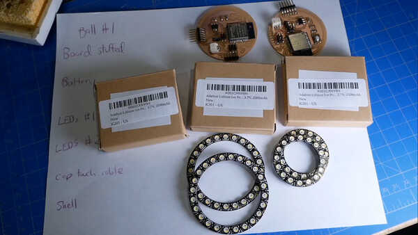
First to inventory the parts I have.
Think it makes sense to just pick the brightest/largest rings, solder jumpers for them. This time I might make smaller ones.
I counted and laid out all the parts I had. I will be using different types of NeoPixels for each ball for now.
I soldered up the remaining 4 NeoPixel rings going from jumper (F) direct to the holes on the pixels.
And I soldered F to solder-wire-loops for attaching conductive thread to the pinout:
And I tied the conductive thread to that loop:
Then I assembled the three balls!
Assembly Steps
- Plug in conductive thread loop
- Attach NeoPixel rings, Ground, then Control, and then Power
- Plug in FTDI
- Press the Button, push Arduino code!
Interestingly I got an unexpected power-draw the first time I programmed it. It didn't happen again.
The colors I was seeing on the pixels didn't match what I had in the UI. I saw a note on the NeoPixel guide about "(some RGBW strips use NEO_GRBW, so try that if you're getting unexpected results!)", so am trying that.
I got a wicked static-electrical shock when I hit the light after experimenting.
One half of one of my 16 GRBW NeoPixel rings is busted. That happened earlier, before I had even soldered it in. Dang! Fortunately I have another 16-er, but it may be a different color temperature.
The replacement strip works great! It seems to be the same color, too.
Taking the 3 Balls for a Spin!
Preparing for Demo Day
I then disassembled the balls to go charge the batteries for tomorrow.