For week 11 our task was to get a microcontroller communicating with something external with network or bus addresses.
This week I wanted to return to the TMAG5170-Q1 that got the better of me back in input devices week. The TMAG is a new 3-axis hall effect sensing IC from TI that communicates over SPI, and is actually still in pre-release. I am planning to use this sensor for my final project as well, so this will be a good opportunity to learn a lot more about clocked communication protocols, and also make some progress there.
Most of my effort this week went into learning to read and understand the TMAG5170-Q1’s 45 page datasheet. As someone who has pieced together a decent number of programming projects without really ever understanding wat was happening below the arduino/python abstraction layer, this was a super exciting week, and felt like it would make a great learning tool as an exercise in “reading microcontroller datasheets-lite.” Disclaimer that lot of what I will write below will sound very obvious to folks familiar with embedded hardware, but hopefully it will be new/useful to folks who still haven’t gone datasheet spelunking. Also below is a neat video from the sensor finally working:
A microcontroller/sensor stores data (settings, outputs, etc) in registers, and we communicate with the sensor by reading and writing from those registers. A register is just a group of bits (so 1’s or 0’s), where the designer of the sensor has specified that (for example) bits 14, 13, and 12, can be flipped to give a total of 8 combinations of sampling rates for our sensor.
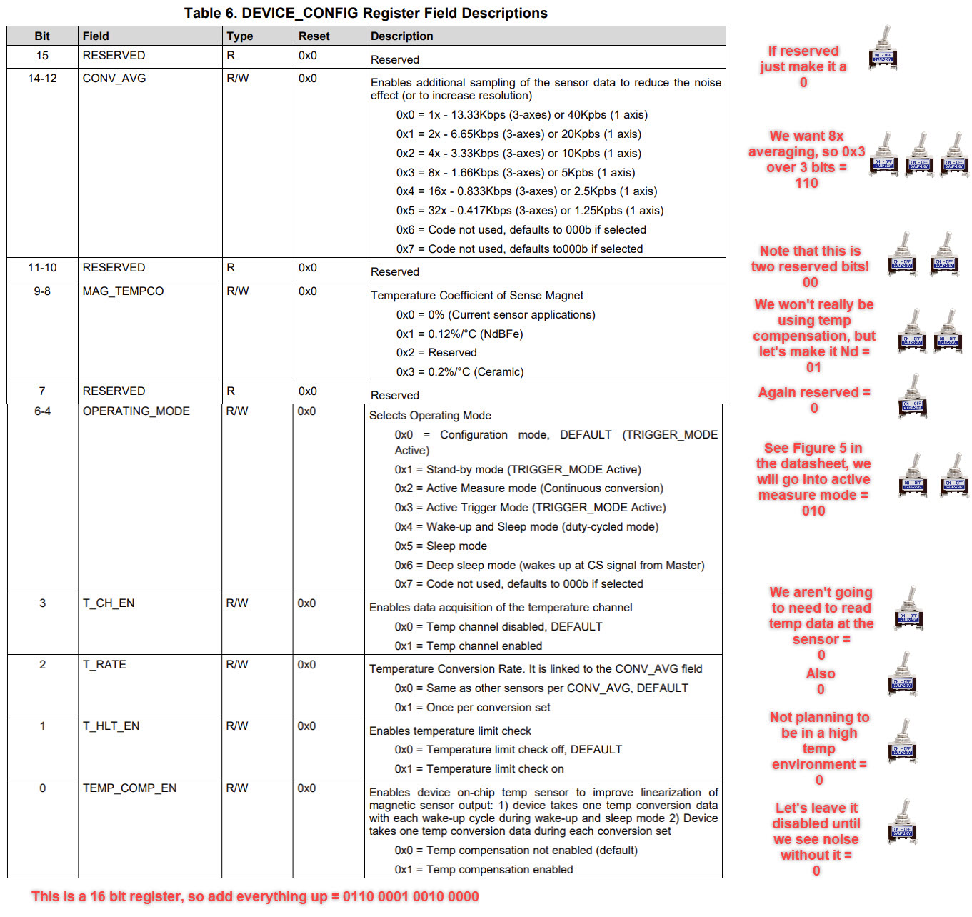
If for example, you were designing a sensor, and you wanted to give the user of that sensor the option to perform averaging over [none, 2, 4, 8, 16, 32] samples inside the sensor (to reduce apparent noise), you might notice that you have 6 options for configuring to choose from. If we are constrained to a binary world, we could use one switch, where off would mean [none] and on would mean [2]. To get to 8 settings, we need 3 switches (bits), leaving 2 of the 8 options unused, where a 000 = none, 001 = 2, 010 = 4, etc. Now just repeat this process for every setting you want. In the case of a microcontroller it could be hundreds of thousands, in the case of the TMAG5170 it’s ~100.
If this still sounds daunting, just remember that the entire process of configuring registers can really be just thought of as looking at + selecting from a series of dropdown menus, except instead of having a nice UI you need to read through a datasheet…
In the case of the TMAG5170, these registers range in size from 16 bits (like the DEVICE_CONFIG register where we tell the sensor’s filtering, temperature compensation, and put it into a range of modes such as sleep/stand-by, etc.), to just 4 bits. I was advised from Mark in Responsive Environments to literally write out the binary on pen and paper for a given register as a binary number, and then if desired convert that into hex using a calculator. I ended up using my computer’s programming calculator a lot this week to jump between decimal, binary, and hex. These registers have addresses, which we will also need to include (note that every time you write to a register you need to write the entire 16 bit register, which will likely contain a lot of settings you don’t care about, so reading and understanding the datasheet is really critical here). Below is a picture showing what this process might look like for the TMAG5170-Q1’s SYSTEM CONFIG register, complete with toggle switch analogy.
Serial Peripheral Interface (SPI) is a communication protocol used by microcontrollers to communicate with one another over short distances. SPI typically requires a minimum of 4 conductors:
SPI is a clocked protocol, meaning that it devotes a trace to signaling when communication is being sent (note that a clock does not need to run at a constant frequency). So for the TMAG, after every rising clock edge, it will look at the MOSI line, and read a 0 if it is low and a 1 if it is high. Also because we are only communicating with a single sensor at the moment, we only need one chip select line, but we could add as many additional sensors as we have I/O without adding additional SCLK, MOSI, and MISO lines.
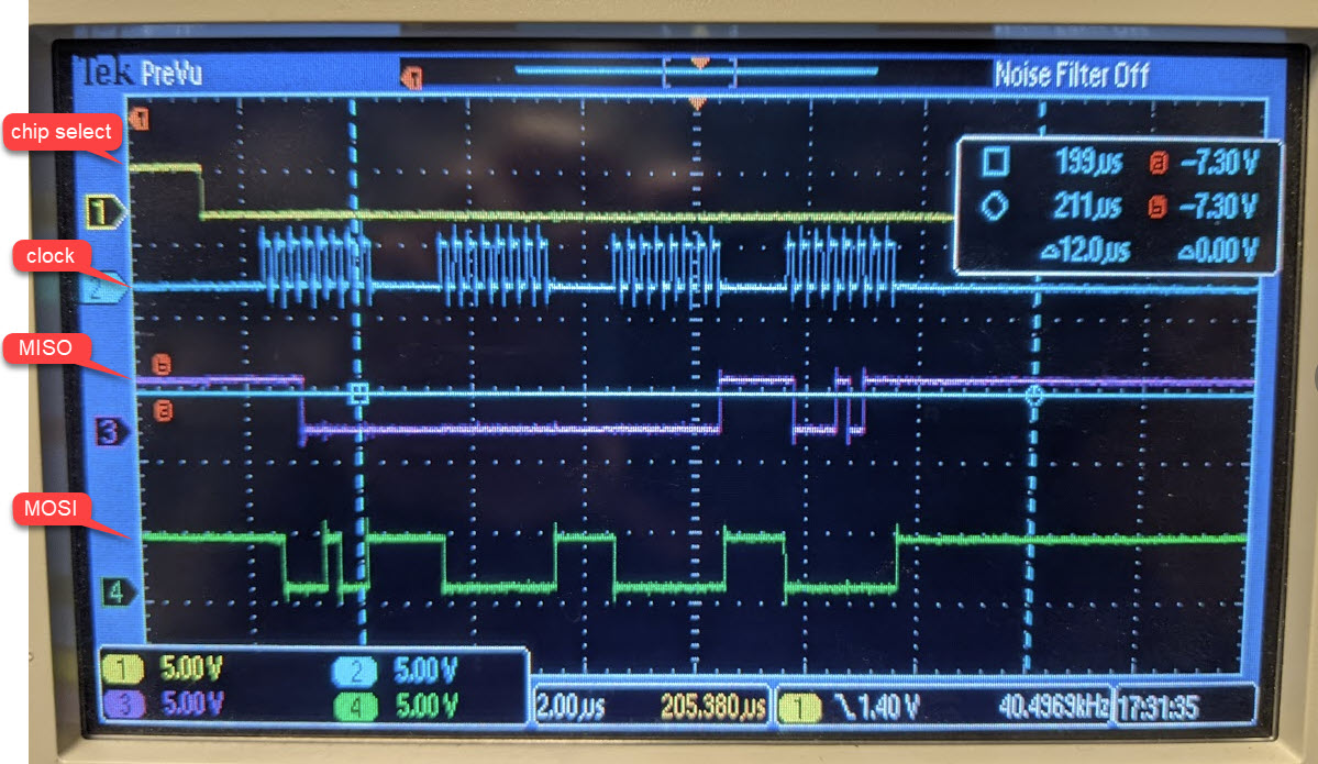
I opted to use the Arduino SPI library, which allowed me to just feed it bytes of data, and then it handles using the SAMD21 SERCOM SPI peripheral. It would be nice to try bitbanging it someday, maybe with a simpler sensor and microcontroller. You can see the code at the end which lays out what we were actually responsible for outside of the library (chip select for example). Below you can see one of TI’s reference write communication phases, as well as one that I had scoped during debugging:
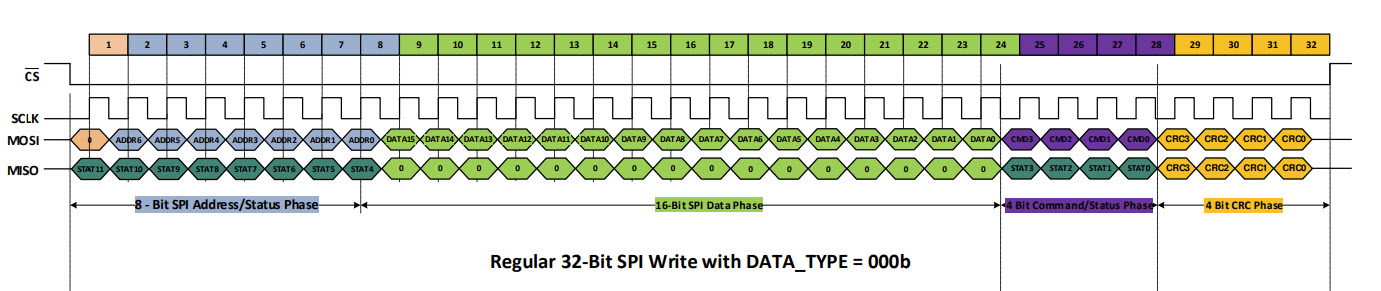
What we are getting in the data phase (in single axis mode) is 16 bits of data representing either flux from +/100mT in either the X, Y, or Z axis, or temperature. Because it’s signed, this means we are getting a resolution of 2^15, or 0 to 32768, which corresponds to ~3uT. For context the strength of our magnetic tape maxes out at about 60mT, and the strength of the earth’s magnetic field is only about 25uT in Boston, so this is far more resolution than we need. Fortunately the sensor has a setting that lets us trade off resolution for measuring both axes simultaneously, which I intend to get working for the final project.
I’ll also mention that this SPI protocol supports 4 bit CRC or a “cyclic redundancy check” (you can see it in yellow in the TI literature above) which is used like a checksum for detecting errors at the end of every communication. It also defaults to on, and it took me an incredibly long time to get it turned off. I spent many, many hours this week in front of an osciliscope debugging, but it was very worth it in the end.
With the code below, one 32 bit communication cycle took 12us, and each was sent with a period of 40us. This means we were communicating at 32 * 1/(40*10^-6) = 0.8 Mbps. This is far from ideal (fast for SPI is in the 10’s of Mbps), and my use of digital writes for chip select and several serial prints probably aren’t helping. The majority of the communication period is empty space when SCLK is not running, so these would be good things to address before my final project. It may be possible to put the SPI peripheral into free running mode as well considering it’s happening in its own hardware.
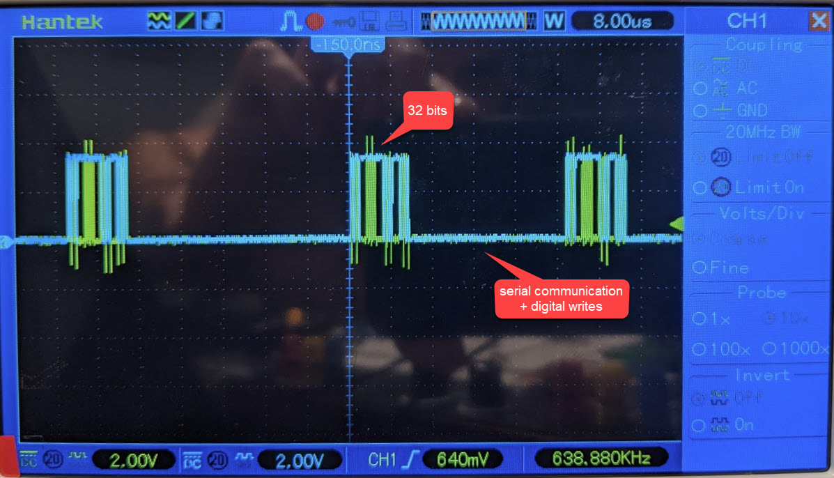
Perhaps more importantly this speed can tell us something about the maximum speed of our encoder. If we were to not want to move further than 50um between the encoder refreshing, we our restricted to moving 50um every 40us, or 1.25m/s (this is assuming that I switch over to the mode that sends X and Z readings in a single 32 bit cycle as mentioned in the datasheet). From experience running CNC tools, 0.75m/s is on the extremely high end of speed for subtractive manufacturing, so this actually sounds fine for the time being. For the final project it would be ideal to run both the X and Y axes off of a single micro, but even with this constraint I don’t think we will have a problem (and maybe even will have room for more digital filtering considering noise is still a problem).
Lastly you can check out the video at the top for an idea of how bad noise is, and how I will be using the sensor (interpolating between poles of a hallbach array for a magnetic linear encoder). What’s unique about my application is that flux in the X axis seems to be a perfect 90deg phase offset from flux in the Z axis, which is usually achieved by two sensors, each measuring flux in Z with a physical 90deg phase offset. One neat thing to point out is that noise is appreciably worse on the X and Y axes vs the Z axis. If I had to guess this is likely because it’s easier to lay out a bunch of hall effect sensing transistors in the XY plane, and therefore measuring flux is easier and more accurate. There’s probably about double the nose in X and Y which you can see from the video, but I am intending to filter most of that away and potentially do more averaging on board the IC depending on how the speed constraints play out.
See you next week, and lastly a big thank you to Mark and Jake who were both excellent (+ very patient) teachers this week, I learned a lot!
And very lastly here’s my code:
/*
  For sensor information:
  https://www.ti.com/lit/ds/symlink/tmag5170-q1.pdf?ts=1605622801161&ref_url=https%253A%252F%252Fwww.ti.com%252Fproduct%252FTMAG5170-Q1%253FkeyMatch%253DTMAG5170-Q1%2B%2526tisearch%253DSearch-EN-everything%2526usecase%253DGPN
  Circuit:
  TMAG5170
  DRDY: pin ____
  CS: pin 13
  MOSI: pin 4
  MISO: pin 2
  SCK: pin 3
*/
#include <SPI.h>

//Sensor's memory register addresses:
const int DEVICE_CONFIG = 0x00; //0x0 is used for writes, should really handle this in the read command
const int SENSOR_CONFIG = 0x01;
const int SYSTEM_CONFIG = 0x02; // this is where we can switch to the 12bit XY sampling mode
const int TEST_CONFIG = 0x0F;
const int X_CH_RESULT = 0x89; //0x8 is used for reads, should really handle this in the write command
const int Y_CH_RESULT = 0x8A;
const int Z_CH_RESULT = 0x8B;
const int TEMP_RESULT = 0x8C;
const int range = 50;

const int chipSelectPin = 13;

void setup() {
  Serial.begin(9600);
  while (!Serial); //hold setup while serial starts up

  // start the SPI library:
  SPI.begin();
  SPI.setDataMode(0);
  SPI.setBitOrder(MSBFIRST);

  pinMode(chipSelectPin, OUTPUT);

  //Configure sensor with syntax (address,dataA, dataB,command+CRC)
  writeRegister(TEST_CONFIG, 0x00, 0x04, 0x07); // from TI support - write a 0x0F000407 which disables CRC in the test config addres //https://e2e.ti.com/support/sensors/f/1023/t/937812
  delay(50);
  writeRegister(SENSOR_CONFIG, 0x19, 0xEA, 0x00);  //0x1 = SENSOR_CONFIG: Configure X,Y, and Z RANGE to be +/-100mT, as well as activating them (they default to off)
  delay(50);
  //writeRegister(SYSTEM_CONFIG, 0x00, 0x00, 0x00);  //0x2 = SYSTEM_CONFIG: This is where we can get the special 2 channels in one 32bit comm setting, to activate XZ you want 0b00000000, 0b10000000, and for ZY 0b00000000, 0b11000000
  //delay(50);
  writeRegister(DEVICE_CONFIG, 0b00110001, 0x20, 0x00); // 0x0 = DEVICE_CONFIG: Set to 8x averaging + no temp coefficient + set to active measure mode + disable temp stuff
  delay(100); // give the sensor time to set up:
}

void loop() {
  // Read X and Z, do math, then print
  int16_t xChannel = readRegister(X_CH_RESULT,0x00, 0x00, 0x00);
  signed short xValue = xChannel + 80; //100/(32768);
  Serial.print(xValue);
  Serial.print(", ");
  int16_t zChannel = readRegister(Z_CH_RESULT,0x00, 0x00, 0x00);
  signed short zValue = zChannel + 50; //*100/(32768);
  Serial.println(zValue);
  //delay(10);
}

//READ COMMAND, returns an unsigned 16 bit int
unsigned int readRegister(byte thisRegister, byte thisValueA, byte thisValueB, byte thisCommand) {
  byte inByte = 0x0;           // incoming byte from the SPI
  int16_t result = 0;   // result to return
  unsigned char bytesToRead = 2;
  byte dataToSend = thisRegister; // Previously concatinated the address and commmand, but we won't do this

  digitalWrite(chipSelectPin, LOW);   // take the chip select low to select the device:
  SPI.transfer(dataToSend); // sending address
  result = SPI.transfer(thisValueA);
  result = result << 8;   // shift the first byte, then get the second byte:
  inByte = SPI.transfer(thisValueB);
  SPI.transfer(thisCommand);
  //Serial.println(thisValueB);
  result = result | inByte;   // combine the byte you just got with the previous one:
  //Serial.println(result);
  digitalWrite(chipSelectPin, HIGH);   // take the chip select high to de-select:
  return (result);
}

//WRITE COMMAND, returns nothing
void writeRegister(byte thisRegister, byte thisValueA, byte thisValueB, byte thisCommand) { //we've rolled command and CRC into one byte
  // take the chip select low to select the device:
  digitalWrite(chipSelectPin, LOW);
  // when we set an SPI.transfer to a variable it will fill up with what's coming in on MISO
  byte writeResult = SPI.transfer(thisRegister); // we concatinated above, now we are sending the complete address
  writeResult = SPI.transfer(thisValueA);  // thisValue is really 16 bits, but we've chopped it to send in chunks of 8 here
  writeResult = SPI.transfer(thisValueB);
  writeResult = SPI.transfer(thisCommand);
  digitalWrite(chipSelectPin, HIGH);   // take the chip select high to de-select:
}