My final project for How To Make (Almost) Anything
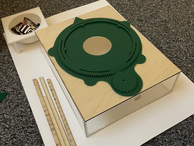
Below is a 1 min video of Bo's final project. The Turtle Box: Time To "Shellebrate!"
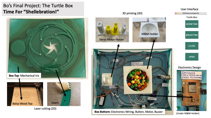
Below is a one-page summary slide of the project
Who's done what beforehand?
The main work that existed for this project beforehand was a 2D CAD template of the iris mechanism I wanted to use for the project, and OnShape gear templates. Additionally, various examples existed on prior project pages for web apps and Processing (Arduino GUI) interfaces for the ESP32 microcontroller. Since this class emphasizes working from scratch, and since I wanted to improve my CAD skills for industry, I choose to make all of the gears from scratch in OnShape.
During the first half of the semester, I was working on a prior project idea and then changed my project design idea halfway through.
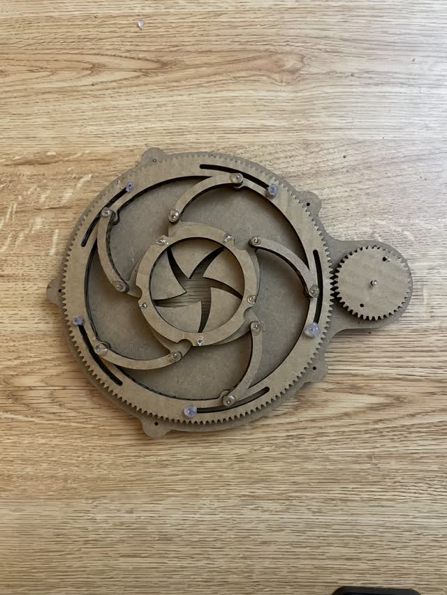
Below is one of the only 2D templates I found for the mechanical iris design I wanted to use, which I found on Etsy:

During laser cutting week, I cut this template out of cardboard to test whether it would work and how it looked:
Next, I started by trying to re-make the entire 2D laser cutting template file myself from scratch! I chose to use OnShape because this is the newest and best alternative to SolidWorks which is a standard in the medical device industry that I working in before I came to MIT. I wanted to get better at using this specific CAD software because more companies were starting to use it, and I wanted to greatly improve my 3D modeling skills.
Below were a few of my initial failed attempts. It took up a LOT of my time and was the hardest part of this project!!!
At this point, I was still working on modifying the gears to make the design from scratch - it's quite hard!!!
There were also a few prior websites with documentation on how to make Processing and Web App interfaces for the ESP32, as well as sites with example code, so those were also existing resources that I used while making my project:
What did I design?
For this project, I designed the following (link to CAD files here, and I've also posted them publicly on OnShape):
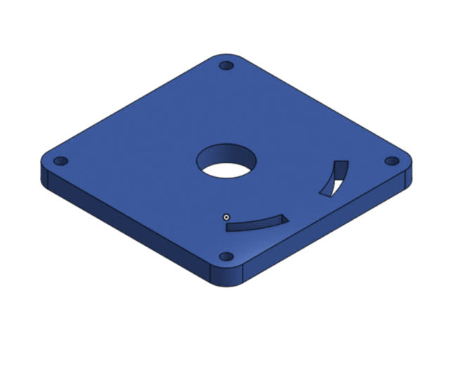
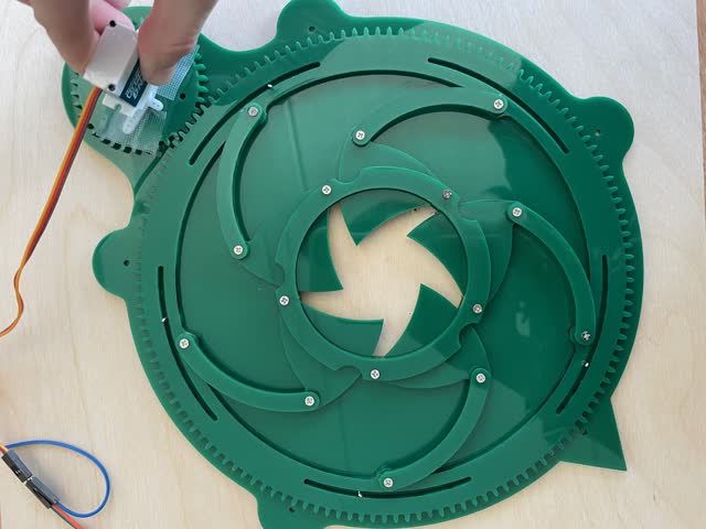
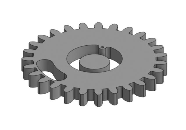
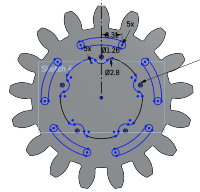
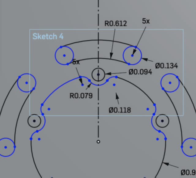
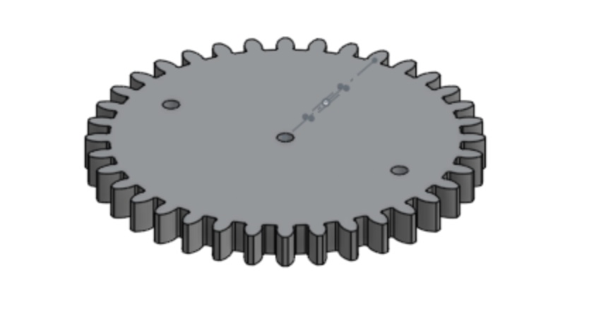
1) Re-designed (from scratch!) mechanical iris gears in OnShape using parametric variables
Turtle shapes:


Link to public OnShape file: https://cad.onshape.com/documents/671ac60f0a432e0e49284d8f/w/ca701a975a5595409a17f6f1/e/044995e47461f7f0285ea8c4
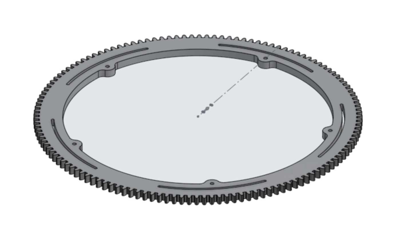
Larger Gear:
Link to public OnShape file: https://cad.onshape.com/documents/eb607bd8586fcfe51484d83c/w/78a72395fbec5816fcd3ff62/e/73a6537978642d526c59a88a
Smaller Gear:

Link to public OnShape file:
2) Designed a 2D laser-cutting file for the turtle box

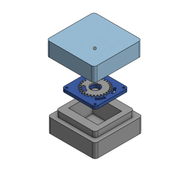
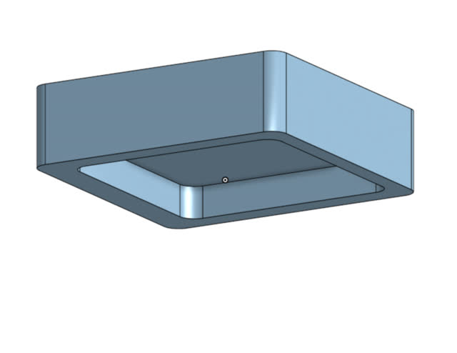
3) Designed a 3D holder for the Servo motor, and a 3D holder for the M&M's
M&M Holder:
Link to public OnShape file:
Servo Motor Holder:
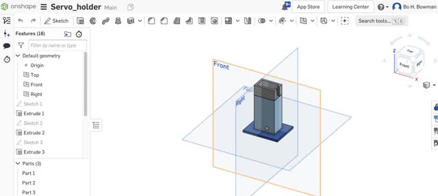
Link to public OnShape file:
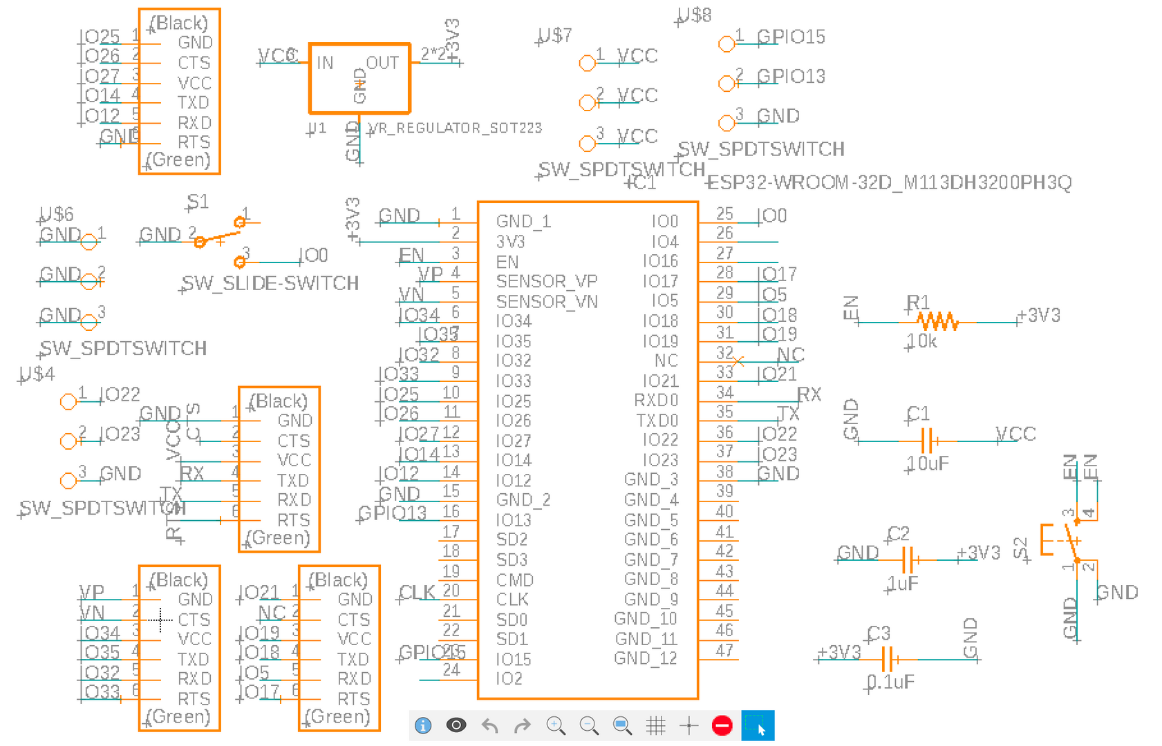
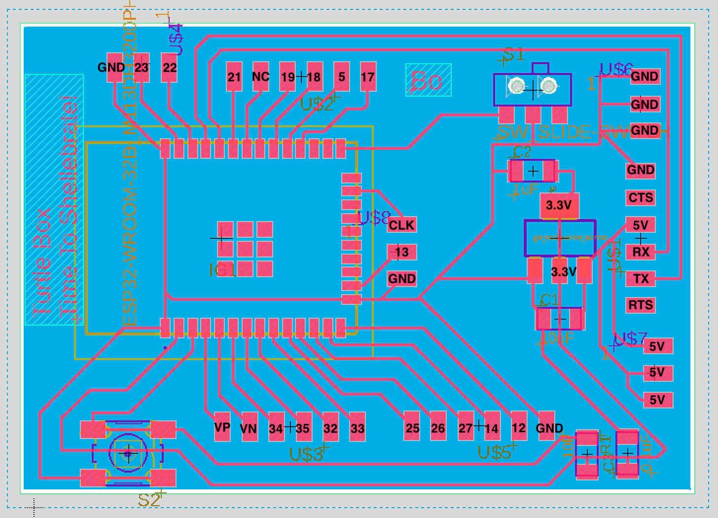
4) Designed an electronics board (with ESP32 microcontroller) in Eagle software
Eagle Schematic:
Eagle PCB Document:
What materials and components were used?
Below was a brainstorming list early on of what materials and components to use:
Possible Gear Materials I Considered:
Online I found some forums saying that I could start by laser-cutting at the same settings for Delrin (https://www.boedeker.com/) as similar-thickness acrylic sheet. However, the Delrin is very expensive so I decided to just go with acrylic/plexiglass. This type of material doesn't necessarily work well to ensure the gears work ideally, however I had actually seen plexiglass gears been made before and they seemed to generally work fine. In the end, the plexiglass acrylic worked fine for the gears and was able to bear the load of turning multiple different gears connected to each other.
For the box, I decided to use either plexiglass, acrylic cement, or a wood sheet laser-cut into the box. Since I wanted to be able to hold M&M's or food inside the box, I decided to use acrylic plexiglass since it is more waterproof and durable.
For the electronics, I knew i would need the following components:
Below is an image of a set of the early electronics components that I collected:
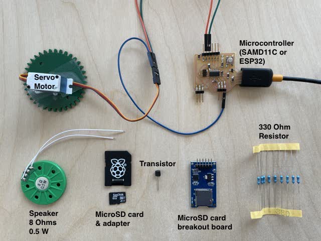
Note that later on, I realized I also needed a MicroSD-to-usb adapter (which I got from BestBuy) and that I needed to use the ESP32.
Material Costs & Vendors
Below is a complete list of the materials & components that I used, where they came from, how much they cost:
| Item | Vendor | Cost |
|---|---|---|
| Balsa Wood Sheet, 1/8" (3mm) thick (quantity 8 sheets) for the box top | Amazon: https://www.amazon.com/gp/product/B01N5CHME9/ref=ppx_yo_dt_b_asin_title_o00_s00?ie=UTF8&psc=1 | $32.99 |
| Acrylic Plexiglass, Clear, 1/8" (3mm) thick, 24" x 36" x 1/8" for the box sides | McMaster Carr, product # 8560K261 (Clear Scratch- and UV-Resistant Cast Acrylic Sheet) or Amazon: https://www.amazon.com/gp/product/B08FDLQJYZ/ref=ppx_yo_dt_b_asin_title_o08_s00?ie=UTF8&th=1 |
$54.99 |
| Acrylic Plexiglass, Green, 1/8" (3mm) thick, 24" x 36" x 1/8" for the green turtle gears | McMaster Carr, product # 8505K745 (Cast Acrylic Sheet, Green) | $3.00 |
| Speaker (8 Ohms, 0.5 Watts) | Amazon: https://www.amazon.com/gp/product/B072KDRQ42/ref=ppx_yo_dt_b_search_asin_title?ie=UTF8&psc=1 | $8.49 |
| MicroSD-to-USB Adapter | BestBuy: https://www.bestbuy.com/site/platinum-uhs-i-usb-3-2-gen-1-memory-card-reader-black/6439244.p?skuId=6439244 | $19.99 |
| M2 Stainless Steel Dowel Pins, Assorted Sizes (M2*10, M2*16) for the turtle gear parts | Amazon: https://www.amazon.com/gp/product/B07BSC3W4T/ref=ppx_yo_dt_b_asin_title_o04_s00?ie=UTF8&psc=1 | $20.99 |
| M2 Flat Head Screws to hold the turtle gear parts together | Amazon: https://www.amazon.com/gp/product/B071W8J5WG/ref=ppx_yo_dt_b_asin_title_o01_s00?ie=UTF8&psc=1 | $15.09 |
| Clear Acrylic Gloss Varnish Paint | Amazon: https://www.amazon.com/gp/product/B002JE60W2/ref=ppx_yo_dt_b_asin_title_o08_s00?ie=UTF8&psc=1 | $15.06 |
| ELEGOO Wires for connecting input/output devices to the electronics board | Amazon: https://www.amazon.com/gp/product/B01EV70C78/ref=ppx_yo_dt_b_asin_title_o01_s00?ie=UTF8&psc=1 | $6.28 |
| FTDI to USB Converter Cable, 3.3V for the electronics board | Amazon: https://www.amazon.com/gp/product/B00DDF8TV6/ref=ppx_yo_dt_b_asin_title_o07_s00?ie=UTF8&psc=1 | $18.99 |
| PLA Filament, 1.75mm, 0.7kg, PLA, WHITE | Amazon / Provided by MIT Architecture Shop for Sindoh 3DWOX 3D Printers | N/A |
| Button Cell Battery Holder, 6V, 2x CR2032 | Amazon: https://www.amazon.com/gp/product/B07QWWBSD8/ref=ppx_yo_dt_b_search_asin_title?ie=UTF8&psc=1 | $5.99 |
| 330 Ohm Resistor | Amazon Kit: https://www.amazon.com/gp/product/B078XV3RK2/ref=ppx_yo_dt_b_search_asin_title?ie=UTF8&psc=1 | N/A (negligible) |
| Passive Buzzer | Amazon: https://www.amazon.com/gp/product/B01NCOXB2Q/ref=ppx_yo_dt_b_search_asin_title?ie=UTF8&psc=1 | $5.99 per pack ($0.59) |
| MicroSD Memory Card, 16GB Class 10 | Adafruit: product ID:2693 |
$39.99 |
| Rugged Metal On/Off Button Switch, 16mm, Green | Adafruit: product ID: 482 Rugged Metal On/Off Switch with Green LED Ring (16mm Green On/Off) |
$4.95 |
| ESP32 Microcontroller (1965-ESP-WROOM-32D(2MB)CT-ND) | WiFi 802.11b/g/n Transceiver Module 2.4GHz ~ 2.5GHz Integrated, Trace Surface Mount | $3 |
| Tactile button | CKN12329-1-ND, TACT 6.0 X 3.5, 2.5 MM H, 180GF | $0.18 |
| Slide Switch | SWITCH SLIDE SPDT 300MA 6V | $0.57 |
| 3.3V Regulator | IC 3.3V100MA LDO VREG SOT23-, LM3480IM3-3.3/NOPBCT-ND | $0.32 |
| 10uF Capacitor | CAP CER 10UF 35V X7R 1206, 490-12425-1-ND | $0.22 |
| 1 uF Capacitor | CAP CER 1UF 50V X7R 10% 1206-, 445-1423-1-ND | $0.07 |
| 0.1 uF Capacitor | CAP CERAMIC .1UF 250V X7R 1206-, 399-4674-1-ND | $0.12 |
| 10k Ohm Resistor | RES 10.0K OHM 1-4W 1% 1206 SMD, 311-10.0KFRCT-ND | $0.01 |
| All Items | TOTAL COST | ~ $250 |
3) Laser Cutting (Epilogue Legend laser cutter)
4) 3D Pirnting (on the Sindoh 3DWox printers)
What worked? What didn't?
What didn't work:
How was it evaluated?
To evaluate my project, I compared against my original ideal of how it would function. For example, I wanted it to be able to make a noise and turn the mechanical iris gear at set times, as well as have some sort of GUI software user interface. Also, to evaluate my progress in fabrication, I compared against a set schedule of what I had planned to do. All in all, it was mostly successful and functional!
What are the implications?
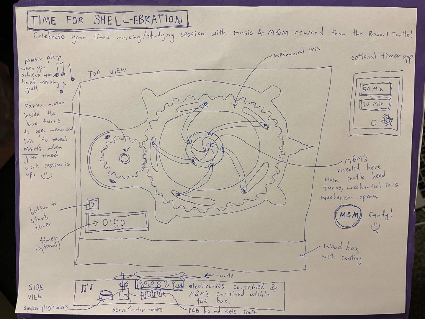
The implications are that this mechanical iris box is possible to make this mechanism driven by a motor, and the turtle box can act as a fun and convenient way to provide M&M rewards after getting a set amount of work done!
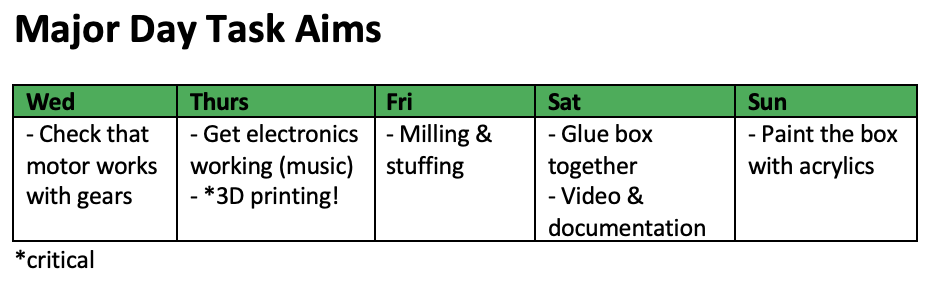
Then, I tracked my progress and compared it to my major day task aims as I went along with the project throughout the week.
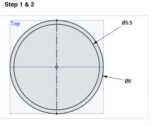
1) Make a circle
2) Make a circle centered along the circle edge
3) Use Spline tool to make a curve along the side
4) Make a construction line (click on Construction tool and then click on Line tool, and then with both selected, create a line, it will be dashed)
5) Use Mirror tool to copy/mirror the spline to the other side too (click on the spline, then click on Mirror tool, then click on the construction line).
6) Use Center Point Circle tool to create a small hole
7) Use Dimension tool and Variable tool to create labeled dimensions for each of the circles you've made. As you can see, typing in # and scrolling down to "new variable" in the popup allows you to name (and input a value for) a variable.
8) Use the Coincident tool to make the spline end dots coincident (touching) the circles they are on top of (for better constraint). To use the coincident tool, first shift-click on both the dot on the spline and on the circle, and then click the coincident tool.
8) Next, use the Circular Pattern tool to repeat the pattern 5 times around the inner circle of the gear. This is a bit tricky! a) Select all parts you want to repeat around the circle (hold down shift key and click on them one by one) b) click on Circular Tool c) Click on the circle you want to repeat the pattern around, d) at the top of the pattern you want to repeat, you'll see something that says "3x" or "1x" or something. Before doing anything else (and you may see a mouse image with a green checkmark on it), double click on the "3x" (or whatever x is on there) and change the text box entry to 5. e) Press Enter f) Left-click near the center of the circle you are repeating around (in this image, it's the very biggest circle around which the smaller circles repeat.
9) Since the splines didn't repeat, we will set more dimensions for the splines (with the Dimension and Variable tools) so that we can make them manually, later on, at each of the 5 points around the gear. As shown here, we have picked another circle pattern that had been repeated around the larger circle, created a spline, and used the dimension tool, typing in # to call out a pre-existing variable when using the dimension tool, so that we can make the spline exactly the same as before.
10) Note that we can again make a construction line (Construction tool & Line tool selected together) and then use the Mirror Tool to copy the spline on the other side of the smaller circle pattern.
11) Next, repeat the same steps again to make the splines for all 5 circles. (SEE PHOTO BELOW. NEED TO TAKE PHOTO)
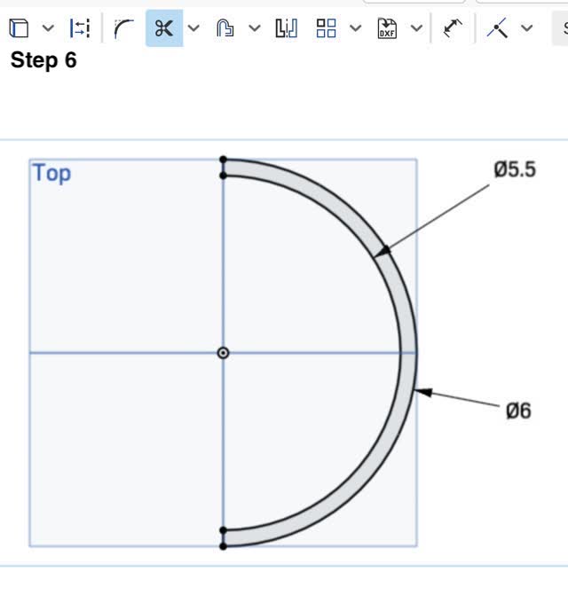
13) Click on the Trim tool and then click on each of the lines you need to get rid of (excess circle parts). NEED TO TAKE PHOTO
OOPS, seems like Spline doesn't work for circular pattern, and trying to do splines individually and mirroring them causes troubles (causes multiple overlapping circles to appear for the larger circle that the pattern is being repeated around).
So... let's go back to trying circles instead of splines...
Here I have learned that the Spline tool cannot be "repeated/copied" using the Circular Pattern tool!!! So I must use other tools/shapes other than Spline (e.g. use the Circle tool + Trim tool instead)
REDO:
0) Make the existing circle bigger, from the template.
1) Make circle, touching the bigger outer circle
2) Use Tangent tool to make the smaller circles touch
3) Make a construction line by clicking on the construction tool and the line tool so that both are selected together
3) use Mirror tool to copy-paste the tiny circle to the other side of a construction line I have made
4) Use Trim tool to remove all things except the original largest circle and the parts we want to keep. (see image in AAPhotos folder)
5) Now, you'll notice when you click the green checkmark on the sketch, that you can see the 3D part now has been cut out with the repeating circular pattern that you just made.
6) Next, make the longer holes (curved slots), starting out by creating two very large circles
6) Next, create a smaller circle, placing it touching one of the larger circles, and make it Tangent to the inner area of the two largest circles.
6) Next, set the distance of the small circle from a tangent line. Use the mirror tool to mirror it, and then the Circular Pattern tool again to copy those two circles around the gear.
6) Next, use the Trim tool to remove unwanted parts of the two largest outer circles.
7) Yay! All done :) Now I can just edit/modify the dimensions to fit the original template.
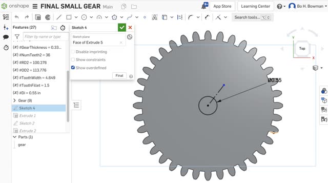
Here's how I made the smaller gear:
1) To make the other smaller gear, work from the same template, from a new copy of it. Edit Sketch 4 in the template.
2) Make a construction line (click the Line and Construction tool so they are both selected at the same time) horizontally along the gear. In my case, I made 2 of these lines, one to the left and one to the right of the center.
3) Make the inner circle smaller (the one that comes with the template)
4) Use Linear Pattern to repeat the circle to the right, and then again do that to repeat it to the left too. Each time, change the repeating pattern distance to the same amount (e.g. smaller) and the number of repeats to 2. a) click on the circle you want to copy with linear pattern b) click the Linear Pattern icon button (or search for it and click it in the upper right hand corner Search Tools box), c) double click on the "3x or 5x or #x" box and then type in 2 (this ensures that the circle is repeated once), d) double click on the distance and it should also similarly show a text box; enter a negative number in order to specify that you want the linear pattern to go towards the left hand direction instead of the right hand direction. (see redo photo 11 part 1 & 2), e) you should see a little picture of a mouse with a left-hand click that has a green check box. Go ahead and "left-click" onto the general area where you have created the linear pattern, in order to "accept" your newly created pattern. Yay! Now it should have worked (see redo image 12). Once you click the green checkmark under the sketch popup, you should then see that the gear has 3 holes in it now as was the intention. (seeimage13)
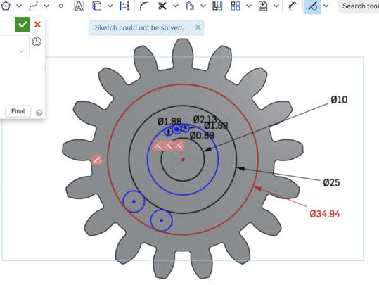
5) Next, edit the two gears so that they are the right dimensions (I measured the distances from the template. \
#Di = diameter of inner circle hole in the gear
#M = number of teeth (3 is more teeth, 4 is fewer teeth)
#PD2 = the diameter from the center of the gear to halfway up a tooth; scales with the outer diameter sizing of the gear
#RD2 is the inner diameter of the gear. The formula is #RD2 = ((#PD2)-(2.5*#M)).
#OD2 is the outer diameter of the gear (at the very end of the teeth tips)
Yay! I easily edited all of the diameters of the small holes. The gear outer diameter and outer teeth tip diameter from the gear center were somewhat harder. For the smaller gear, the outermost inner diameter was 3.947861 inches. Since we want #RD2 = 3.947861 in, solve for #PD2, where #M is 3:
#RD2 = ((#PD2)-(2.5*#M))
3.947861 in = ((#PD2)-(2.5*3))
#PD2 = 3.947861 in + 2.5*3 = 100.2756694 mm + 2.5*3
#PD2 = 107.7756694 mm
But now we can see that when we increased the gear diameter by a lot, we now suddenly see an inner unwanted circle and a rectangular hole show up. How do we get rid of these? The solution is to edit the sketches so that the rectangle is turned from lines/rectangle into construction geometry instead (this will ensure that the rectangle is simply used as reference geometry rather than as something that gets extruded as a rectangular hole!) (insert CAD-redo-14 image here)
5) In Sketch 3 (or in whichever sketch layer of the gear template contains the rectangle in the sketch), select the edges of the rectangle and then click on the Construction tool. When you hit the green checkmark to exit out of the sketch and accept it, you should now see no more rectangular hole! Yay! (CAD-redo-15 image insert here)
Next, I deleted Extrude 3 altogether. In Sketch 2, I selected the unwanted circle and clicked on the Construction Tool to then make into reference geometry.
6) Modify the number and sizing of the teeth for the mini (smaller) gear. Note that changing #M changes the outermost inner gear radius, so instead we have to re-calculate #PD2 after modifying #M.
TBD>>>>>>> I haven't done this yet!!!!!
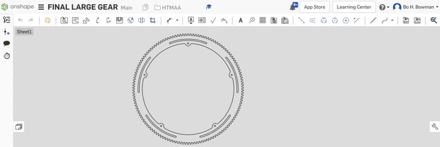
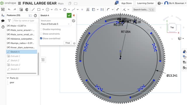
6) Modify the larger complicated gear to be the right sizing.
The outermost inner diameter is: 15.526309 in (measured from the template)
#RD2 = ((#PD2)-(2.5*#M))
15.526309 in = ((#PD2)-(2.5*3))
#PD2 = 15.526309 in + 2.5*3 = 394.3682486 mm + 2.5*3
#PD2 = 401.8682486 mm
So, type that number in for #PD2 for the larger complex gear template. Do not include "mm" when typing it in. Note that it may take a while for the 3D model to update, so wait patiently until it finishes. (CAD-redo-16 image here)
7) Repeat the steps from before to turn the unwanted rectangle and unwanted circle into construction geometry so they do not show up in the 3D model. (Edit Sketch 3 to make the rectangle into construction geometry, then delete Extrude 3, then edit Sketch 2 to turn circle into construction geometry) (CAD-Redo-17)
8) Next, modify the other geometry of the complex gear to match the original template.
Note that I will need to work off of a smaller version, Gear Attempt 2 - partway version, and then extrapolate to repeat it for Gear Attempt 2 (larger file), which takes larger to regenerate/update.
TODO: work off of Gear Attempt 2 Partway Version, documenting steps, to make the geometry the right dimensions. Next, work off ofGearAttempt 2, repeating the steps for the longer-to-generate model.
a) Delete the distance 0.249, and instead use the Dimension tool to dimension the inner circle of the outermost inner circular pattern.
(CAD-redo-18 & 19)
b) Set the radius as a new variable dimension by double clicking on it and typing in #, then scroll down to create a new variable that you can change.
(CAD-Redo-20)
The diameter should be 14.108078 in diameter, per the template, so the radius is 14.108078 in / 2.
Now the gear looks like this: (CAD-redo-21 image)
c) Change #Di to modify the inner circle pattern diameter. Per the template, the diameter should be 13.24091 in.
d) But now we see a giant random semicircle appear. How to get rid of it? First, make the off-center centerpoint of the tiny hole to be coincident (CAD-redo-21-part2&3)
e) Next, (CAD-redo-22 image) Just click on the Coincident Tool, then click on the midpoint of the giant semicircle, then hold shift and click on the midpoint of the giant main gear. This should make the two centers coincident!
(CAD-redo-23 image)

d)
Next, I should make a copy of the gear, and then work off of it to fix the spacing around the holes to be proper!!
I just remade the holes altogether.
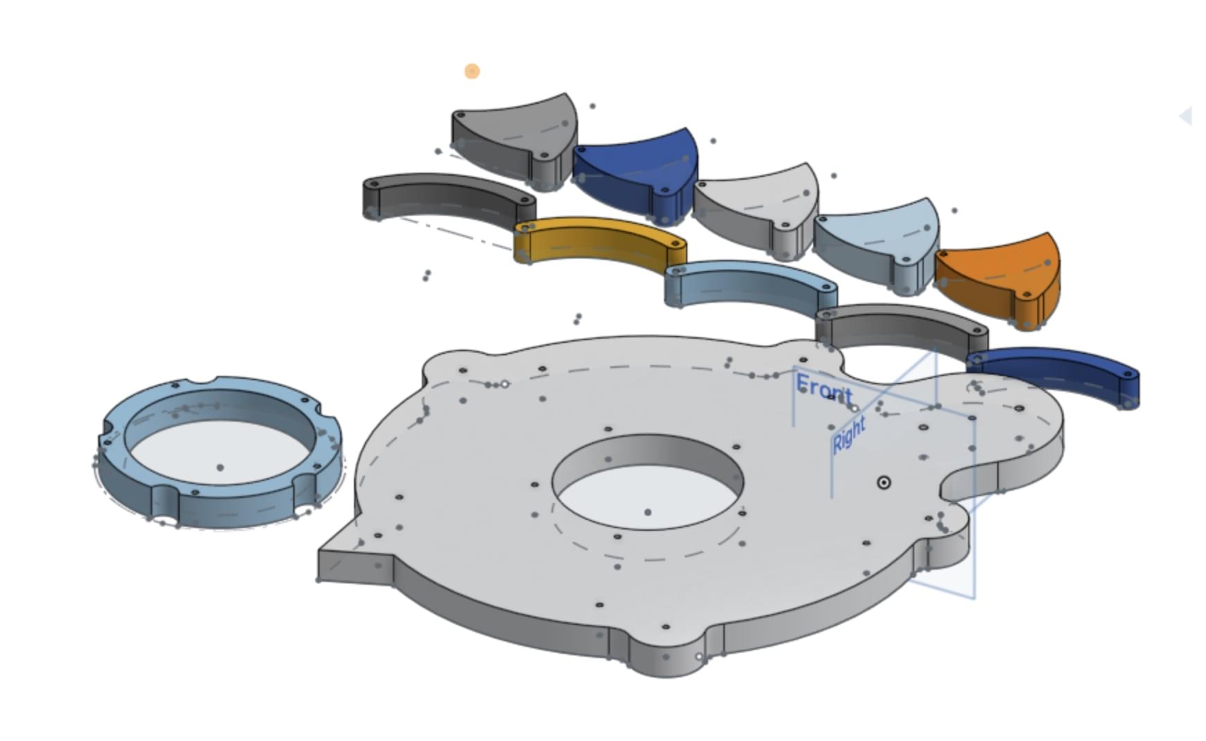
1) Next, I moved on to making from scratch the rest of the mechanical iris template. I used the following tools:
2) To create a circular construction line to align the different semicircles on the outside of one of the pieces, use Construction tool; click on Center Point Circle Tool an click on Construction Tool so that both are selected, before creating a circle, which appears dashed when you make it and which acts as reference geometry.
3) After making and dimensioning everything, I then used the Circular Pattern tool to repeat the pattern around the circle. Remember to always do the following steps while using Circular Pattern:
a) Click the items you want to copy/repeat
b) Click the "3x" or __x" text that shows up, and change it to the number of repeats you want. In my case, I double clicked on it, typed in 5, and then pressed Enter to accept.
c) Select the center of the repeating circle you want to repeat around (click and drag the center point of the existing "repeat pattern" circle and drag it to the desired location.
d) Left-click somewhere in the center fo the pattern, to get rid of the left-click mouse symbol and to accept the repeated circular pattern.
(CAD-redo-26,&27, 28)
3) Lastly, I used the Trim tool to remove any remaining segments that I did not need, for example to create the semicircles. (CAD-redo-29)
Then, I repeated the above general steps to create the rest of the CAD file.
For the curved petal pieces:
1) Make many circles and dimension them (center point circle tool, dimension tool) (CAD-redo0-30)
2) Use Trim tool to remove unwanted segments (CAD-redo-31)
3) Use Linear Pattern tool to repeat the curved petal piece 5 times along a line. Click Linear Pattern tool, then hold down shift and select all the lines/curves, then double click the "3x" and change it to 5, and lastly change the spacing (double click and change it to 4").
(CAD-redo-32, 33,45)
Next, make the curved connectors:
1) Create circles and use dimension tool to dimension them correctly (CAD-redo-35)
2) Use Trim tool to remove unwanted segments (CAD-redo-36)
3) Once again, use linear pattern tool with 5 repeats and 5in spacing, to copy the curved connector 5 times. (CAD-redo-37)
Lastly, to make the turtle outline, use similar as above techniques:
Next, I just need to laser cut the turtle and gear pieces from the acrylic plexiglass sheet that I have, laser cut the box, and wire together the electronics!
So, the next step I took in OnShape was to create a Drawing, since I realized extruding the shapes and then exporting as .STEP file and then importing in Rhino 7 caused weird lines to show up. Instead, I found that I could:
1. Click on the plus icon/button in the lower left hand tabs corner in OnShape to create a Drawing
2. Select 1:1 for the ratio and Top for the view,
3. Move the resulting drawing away from the main template rectangle before left clicking
4. Import the drawing .DXF file into Rhino 7
5. Delete the rectangular template box, leaving behind only the desired drawing
6. Repeat for the other gears, by Opening in Rhino (with inches settings), selecting around the gear, copying, and then pasting into the main Rhino file.
7. Scale the drawing (type Scale into the command line, then select one point and then another point, then type in the dimension (e.g. 3in) that it's supposed to be between those two points. Lastly, press Enter to accept the scaled drawing. (CAD-Redo-55-Rhino)
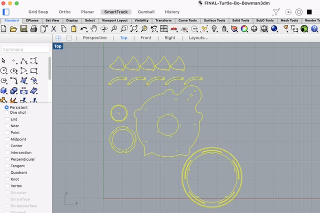
Here was the combined Rhino file that I used for laser cutting the turtle:
Since the 120W laser cutter was down, I decided to use the 60W laser cutter.
Settings for 3mm acrylic (1/8" thick), for 60W laser cutter: 8% speed / 100% power / 100% frequency, used the architecture shop 60W laser cutter and it worked great! A little bit of burnt edges and a small bit of flames but that was fine (will try slightly lower power next time; 95% power).
95% power also worked just fine! There was some flame apparent that was worse at the bottom of the acrylic sheet though because the sheet was somewhat bent unfortunately, but I couldn't help that much.
Next, I screwed in M2 screws into the laser-cut green acrylic into the base of a balsa wood sheet (3mm thick). For the parts that could not go through into the wood, I used a hot glue gun to glue from the bottom.


Next I laser cut the 3mm (1/8") thick balsa wood! First I tried 10% speed / 80% power / 10 Hz frequency, which cut through nicely. To reduce burn marks, I decided to try a second time, except with lower power (65% power). 65% power was too low, so I did a double run of the 65%. That didn't work either, so I tried again: 10% speed / 75% power / 10Hz frequency. This setting worked JUST right for the 3mm (1/8") thick balsa wood sheet!
(Note that the chart on the wall in the architecture shop says 20% speed / 50% power for 1/8" acrylic plexiglass)
Here's a useful chart for determining laser-cutting settings:
https://www.epiloglaser.com/assets/downloads/fusion-material-settings.pdf
Note that on the architecture shop 60W laser cutter, the settings above work well but I'd recommend going with 10-20% lower power than is specified. That's what worked well for me, and it prevents possible chance of fire!

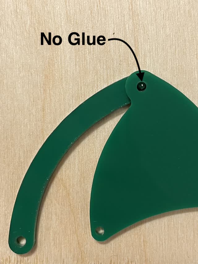
Next, I re-cut the turtle shape, fixing the CAD file to remove the edge dots on the turtle's feet and tail:
3mm (1/8") thick green acrylic plexiglass sheet
Used the 60W laser cutter with 8% speed / 90% power / 100Hz frequency.
Once again, even with lower power settings, the acrylic still showed soem minor flames, but it cut through well.
So then I tried 80% power instead.
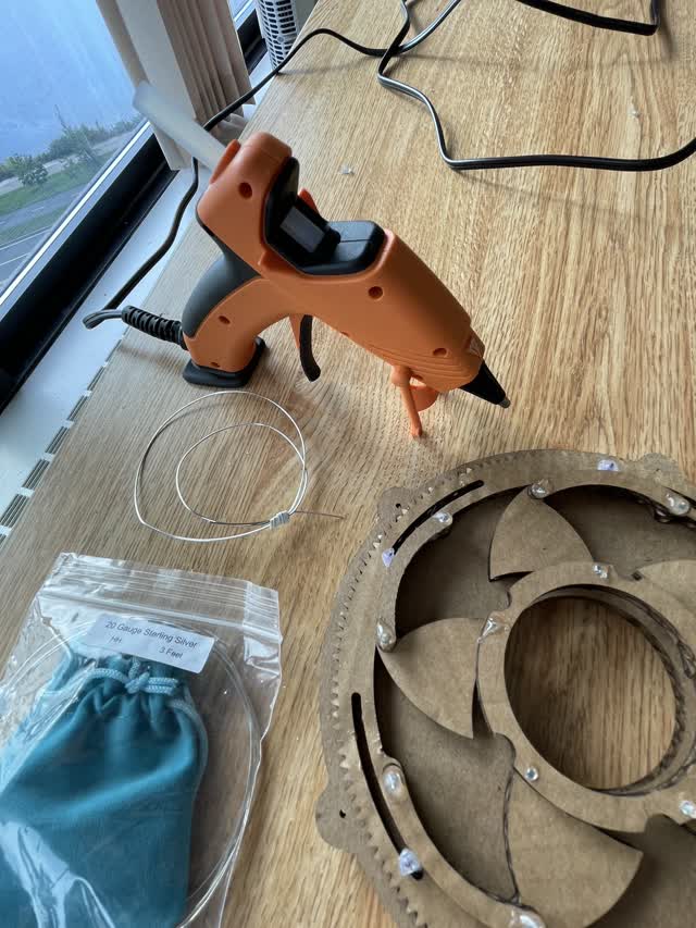
Next, I screwed in and assembled the green turtle onto the laser-cut balsa wood sheet. Everything went well, except when I got to the part where the screws stick out for the largest gear. The screw diameter was too large to accommodate the large gear, and perhaps also I should have made the large gear somewhat larger in diameter by a few mm to accomodate this situation.

So, I used soft stainless steel jewelry wire and jewelry tools to bend little pieces of wire to use instead:
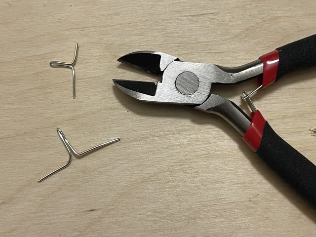
Then I fit the little bent wire pieces into the underside of the turtle cutout piece:
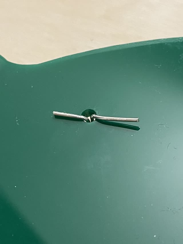
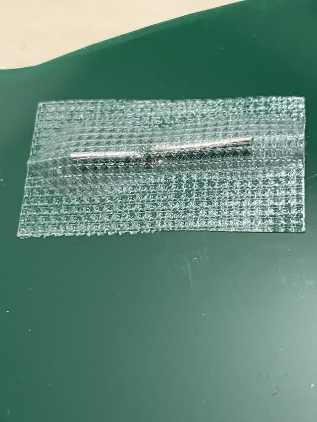
And then I secured them with tape:
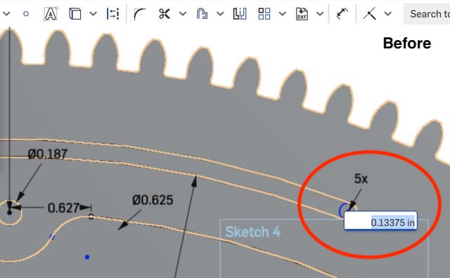
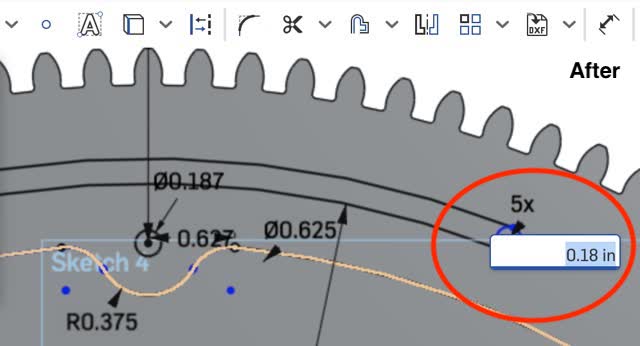
To permanently fix this issue, I decided to re-laser-cut the green turtle so that the diameter of the curved slots in the outer gear would be larger to account for possible melting/burning of the plastic (e.g. 0.18 in instead of 0.13375in diameter of the curved slot). I also changed the hole at the head of the turtle to be 0.3125 (7.9mm or 5/16") to accomodate for inserting the spokes/motor "wheel" up through the design.
Next, I re-exported all 3 of the new drawing files (large gear, small gear, turtle & curved parts) from OnShape as STEP files, imported into Rhino in the inches setting, scaled each of the 3 parts properly, and then selected and copy-pasted them to put them all into 1 main Rhino file. Hooray! Now, it's time to re-laser-cut the turtle again! This time I used 10% speed / 80% power / 100Hz frequency for the green acrylic plexiglass that is 3mm (1/8") thick. This was a slightly higher speed and lower power than before, to reduce the chance of flames/burning. The chart on the wall for 1/8" plexiglass recommends 20% speed / 50% power. So maybe I should actually instead try 20% speed / 70% power / 100Hz frequency!
Tried again with 10% speed / 85% power / 100Haz frequency. This setting worked best for the 3mm (1/8") thick green acrylic plexiglass sheet.
YAY!
Here's the final Rhino turtle CAD file:
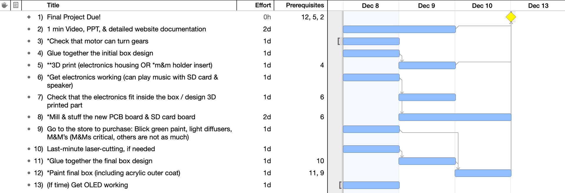
Project Management:
At this point I realized that I need to start planning my time better! So I made a Gannt chart for the remaining few days before final deadline:
In reality, this is a lot to keep track of, so on a higher level these are reasonable tasks for me to expect to finish each day in order to finish the final project on time. Thursday is going to be a super crunch day!
Yay! I was able to get my 6V Servo motor (which can be powered by 5V) to successfully turn the gears of the turtle! I used a Servo motor because they can take specific set distances. Note that the pins for this Servo motor include 5V, GND, and one PWM analog pin.
Next, I worked on the most critical part of the electronics which plays music / audio files: Speaker. Here were the two tutorials I was deciding between:
Option1: https://create.arduino.cc/projecthub/skyline/diy-song-player-with-arduino-uno-503fc1
Option 3: https://www.arduino.cc/en/Tutorial/SimpleAudioPlayer
I decided to go with Option 1 first since I had already purchased all of those materials:
Here is the circuit aimed to make based on the tutorial that I found:
https://create.arduino.cc/projecthub/skyline/diy-song-player-with-arduino-uno-503fc1

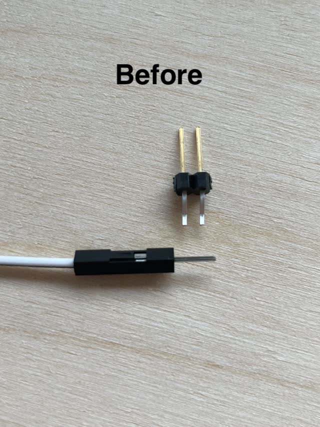
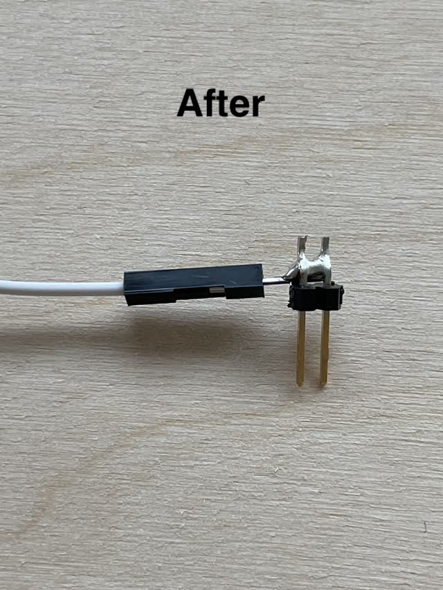
Note that for the connection between 5V, speaker, and VCC of the MicroSD Card Adapter, I soldered a wire to a 2-pin header to allow for two wires to connect to one wire (e.g. split connection). I got this idea from a youtube video here https://www.youtube.com/watch?v=uYf7vFREV98 which explains what to do if you are using an Arduino and run out of GND connections. A very useful trick!
Soldering for creating a split-connection wire:
Instead of using an Arduino, I first considered using my first PCB board which I had iteratively designed (e.g. spiral development process) during input week and output week specifically for my final project to be able to handle a motor as well as multiple other pins for the SD card module. Here it is!
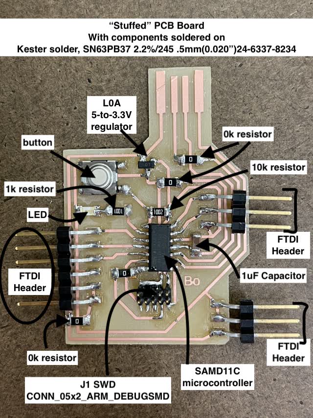

As you can see above, I designed the board to have multiple 5V output pins and multiple GND pins as well. This way, the board could handle both a motor as well as music playing capability.
However, I realized one catch: That I hadn't added header pins for the MOSI and MISO connections MicroSD card module! Luckily, since I had planned via spiral development, I had specifically designed iteratively my next board for networking week with the assumption that whatever could go wrong, would go wrong (Murphy's law). I had based this second design from the original, except with the ESP32 instead of SAMD11C, and even more pinout options in case I would need them for the final project. Luckily, I had planned in advance and was able to easily use my last iteration of the board for connecting to MISO & MOSI!
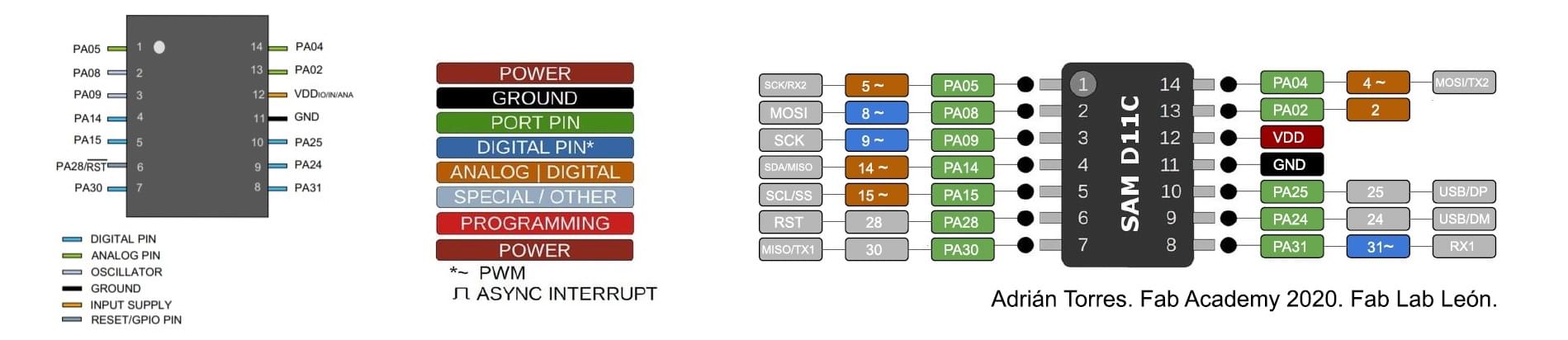
As you can see below, although the SAMD11C does have the capabilities I would need to include both the speaker / microSD module as well as the motor, I would have needed to re-mill and re-stuff this board with the MOSI (PA08) and MISO (PA30) pins available to use by adding extra connector pads with additional headers. Note that pin CS (chip select) can be any pin for example pin 4 on an Arduino which is a normal digital pin (no PWM required). SCK is PA09 on the SAMD11C. As a refresher, here is the SAMD11C pinout diagram:
So, I decided instead to switch to my ESP32. Based on the spiral development process, I had also designed for the final project in case I wanted any wifi or bluetooth capabilities, and once again, I had designed it with multiple headers like a development board so that I could have access to all the pins for my final project.
Here is the board which I had iteratively designed for my final project:
[INSERT 2 PHOTOS HERE OF FINAL BOARD!!!!)
Here is the pinout diagram for the ESP32 microcontroller the I used for the above board design:
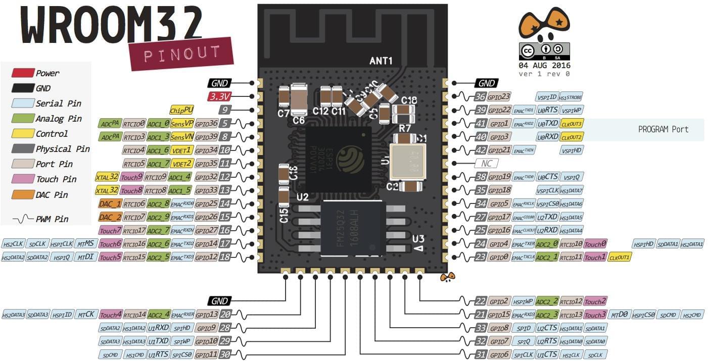
Based on this ESP32 pinout reference documentation, we know the following:
So, I need to now make a header connector for GPIO 6 in order to accommodate for the final project microSD card, as well as additional GND and 5V output pin headers.
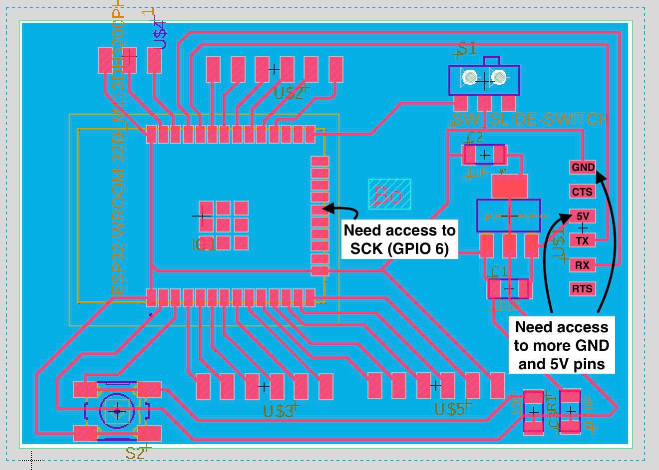
After redesigning the ESP32 board in Eagle with a few more headers for my final project, this is what it looked like:

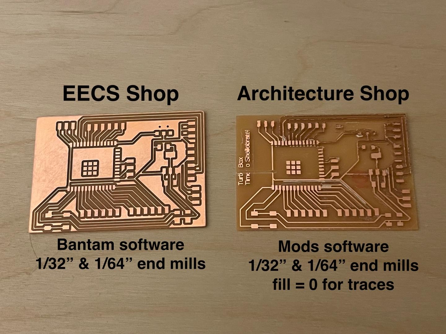
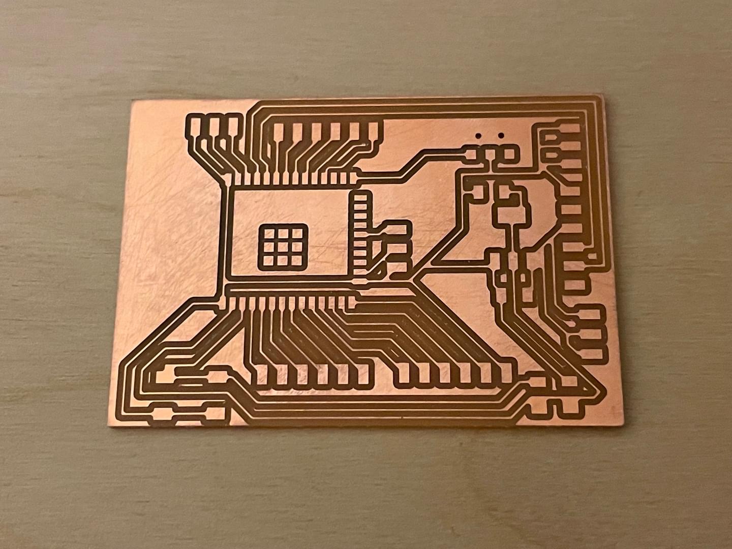
Time to mill the board! I used the OTHERMILL in the EECS MIT shop. I exported a .brd file from Eagle (File > Export > .brd) and used the Bantam tools software for the mill (instead of mods).
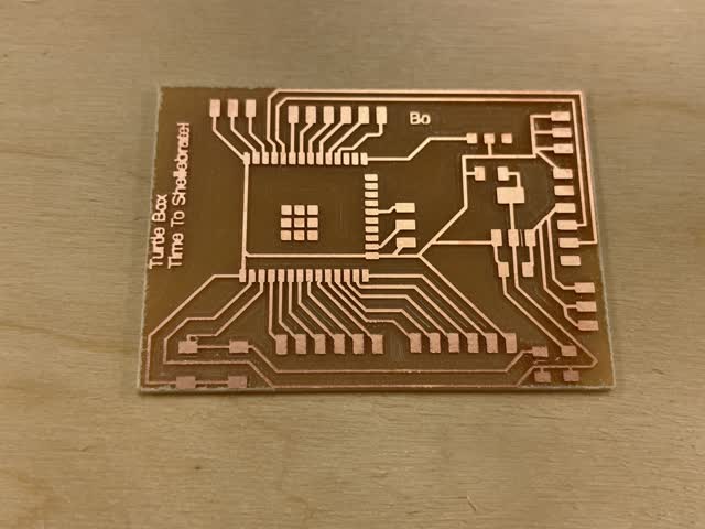
Here was the final milled board:
Then, I stuffed it (soldered on the components):
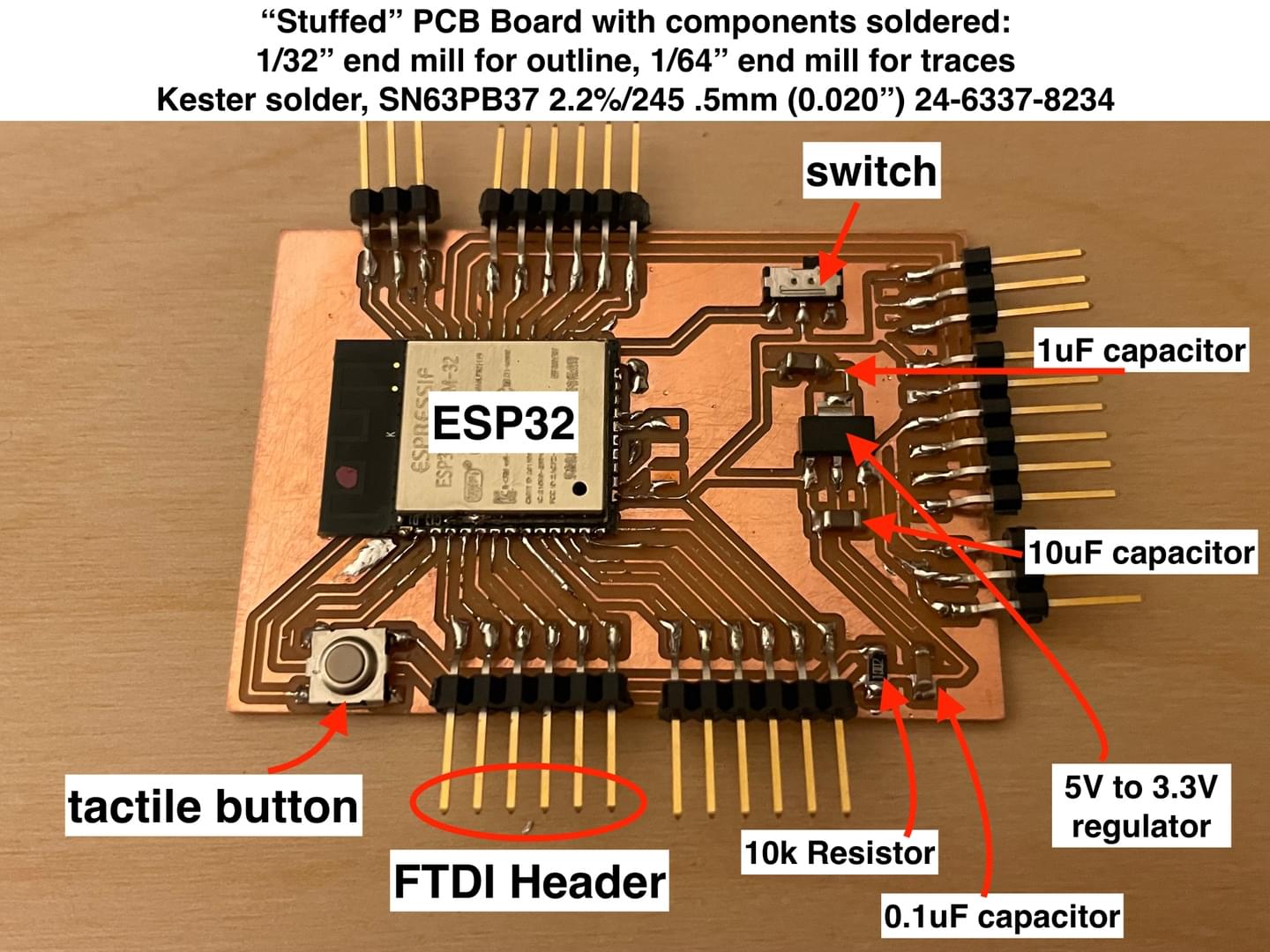
During office hours, I found out the following from TA Anthony Pennes on how to connect the wiring once I finished milling & stuffing my board:
The TA also gave some additional tips on programming:
I also re-milled a second copy of my board on the SRM-20 in the architecture shop using mods software and fill=0 for the traces:
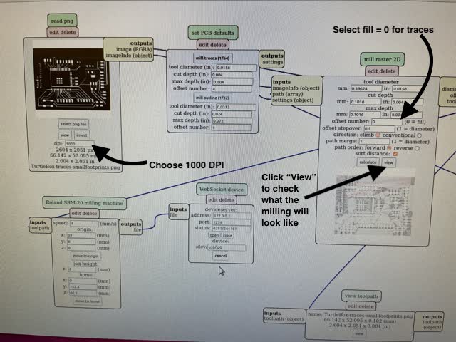
Note that I had manually edited the footprints/pads of the imported ESP32 file to be 66x32 instead of the default, in order for the pads to show up distinctly in mods / when milling the board.

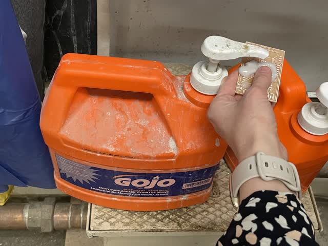
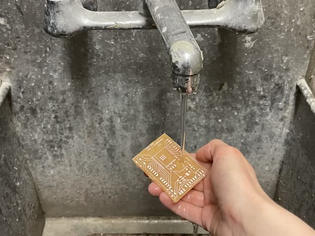
Then I cleaned the board with abrasive soap:
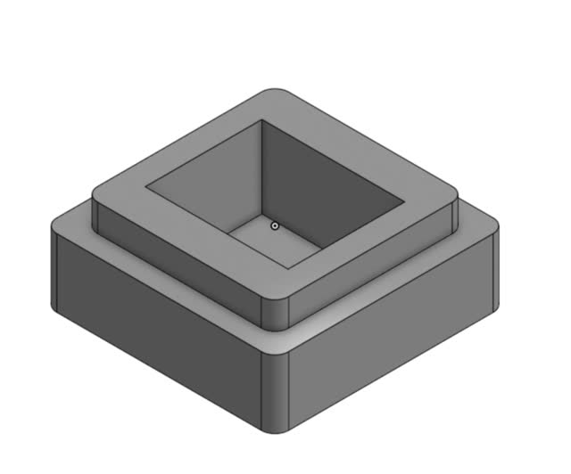
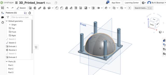
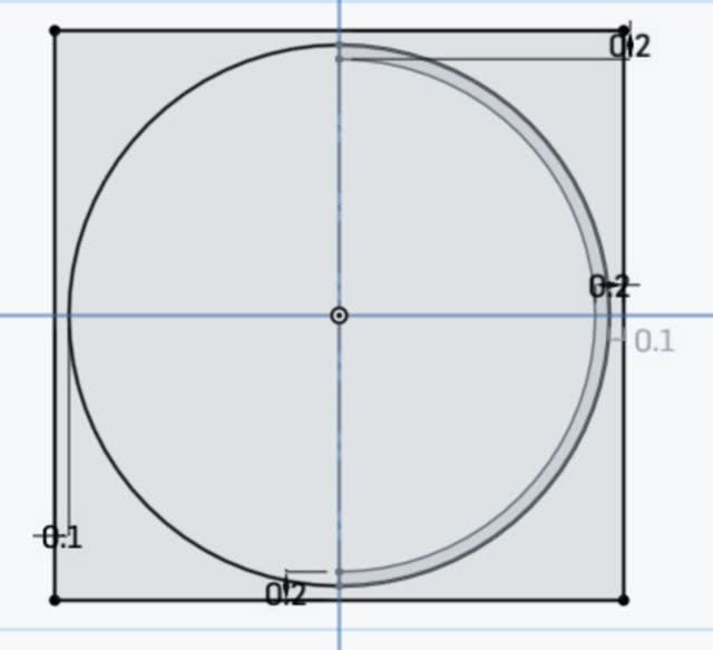
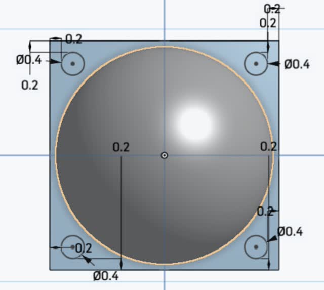
For the 3D printed m&m holder insert, I did the following in OnShape:

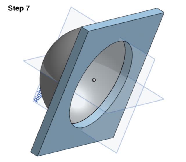
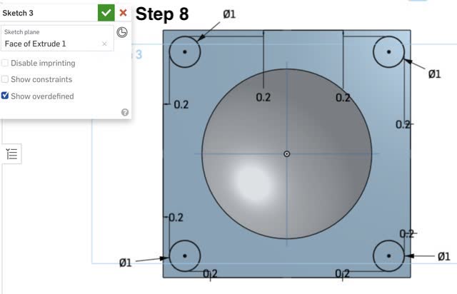

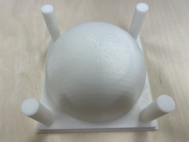
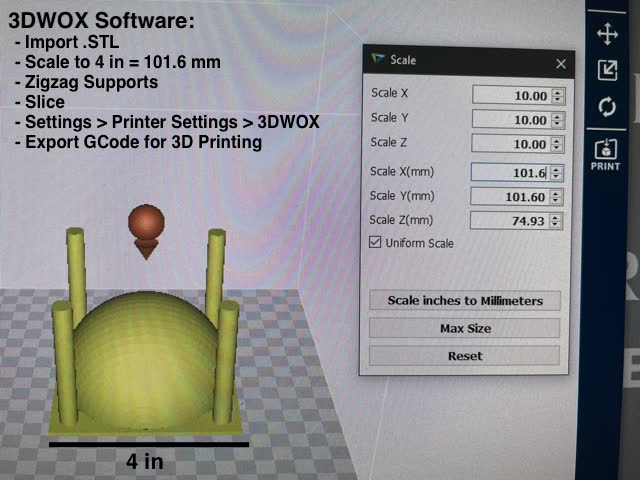
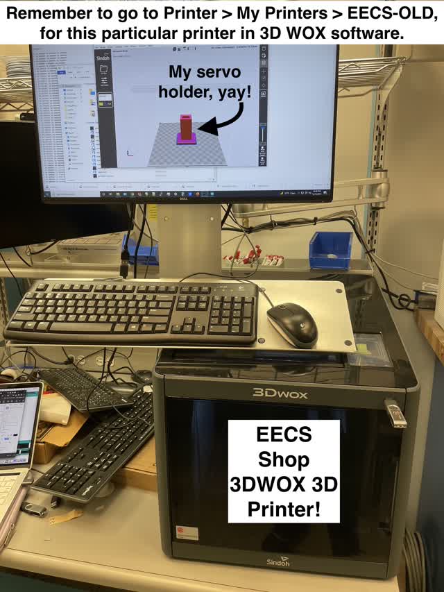
For the 3D printing process, I used the 3DWOX software on the architecture shop computer in 3-412 to export the GCode for my above model, and then printed using one of the Sindoh 3D printers in 5-414 of the architecture shop.
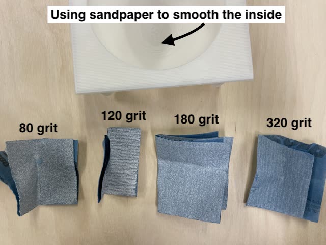
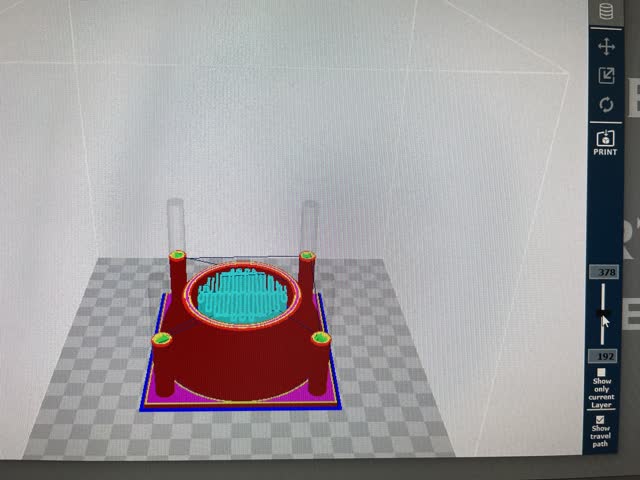
Once I finished printing the part, I used sandpaper to smooth out the inner part which had little pieces leftover from the zigzag support structure on the inside during printing.
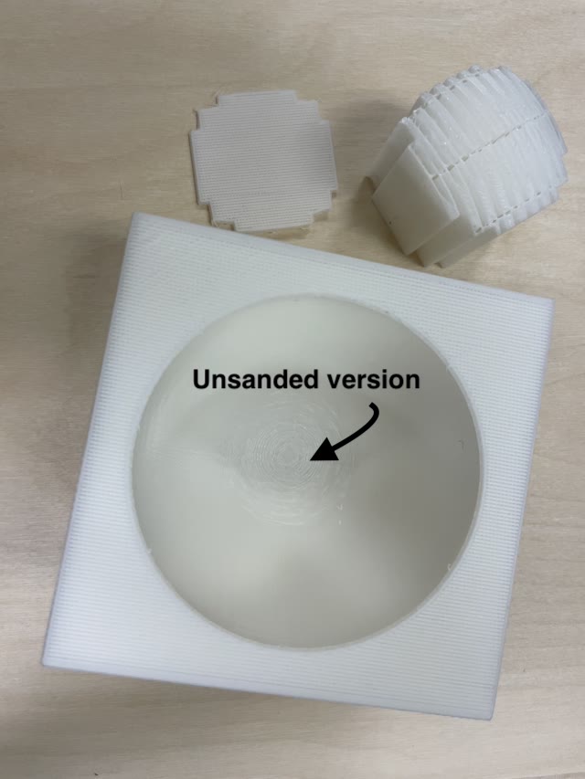
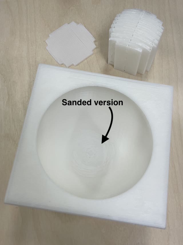
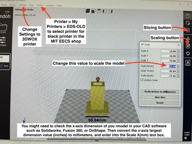
Three BIG learnings were 1) scaling!!! 2) selecting printer settings correctly!!! and 3) checking dimensions carefully before 3D printing!
So, I re-made the OnShape CAD file as follows, to ensure the cylindrical columns would be long enough and scaling would be correct. To do the scaling, I clicked on the scaling icon in 3DWOX (5th icon down from the right) and then typed in 101.6mm for ScaleX(mm), which is the same as 4mm which is the correct x dimension for my updated part.

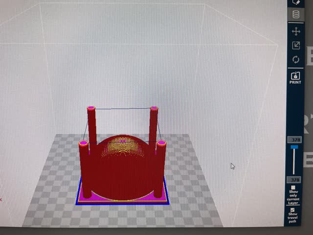
In the 3DWOX software, I scaled (101.6mm on x-axis in the 3DWOX software is 4in x-axis dimension), sliced, and checked the zigzag supports:
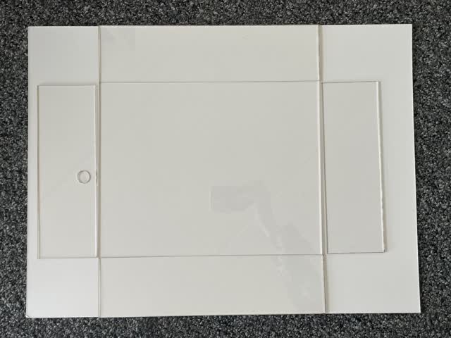
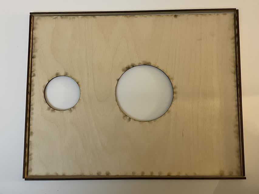
Next, I realized that my cutouts for the wood pieces were not centered - oops! So I fixed the CAD laser cutting file to accommodate for this, and planned to re-cut the wood top.

I planned to use 15% speed / 75% power / 10Hz frequency for this next redo laser cutting run on the 1/8" (3mm) thick balsa wood.
Great! it was much improved from last time, with not as many burn marks!

At this point I was a bit behind schedule. Although I planned to get the electronics (music) working on Thurs, I was unable to do so since office hours were so crowded and since I needed to re-mill and re-stuff my board anyway. I also made a mistake which is that I forgot to but a microSD usb adapter to load music onto the microSD card! So, I quickly made a last minute purchase to get one by Friday, and in the meantime I milled & stuffed my board on Thursday instead of on Friday.

Next, on Friday I worked early on assembling the box together with a hot glue gun. This task can be done anytime so I did it in the morning as a mini break!
Box assembly options I considered:
After considering the above 3 options, I decided to use a hot glue gun because acetone welding is more toxic, while press-fit is more ideal with wood and less ideal with plastic (since plastic can creep over time and doesn't have as much bend, which makes high tolerances necessary and can make press-fit designs a pain to deal with for this material.
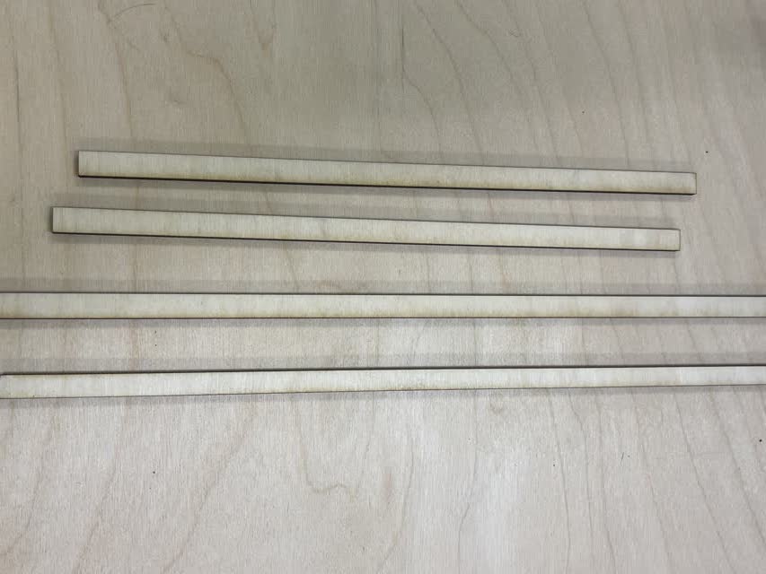
Here are the laser-cut pieces that I made using the laser cutter (note the hole on one side in case I decide to add a button):
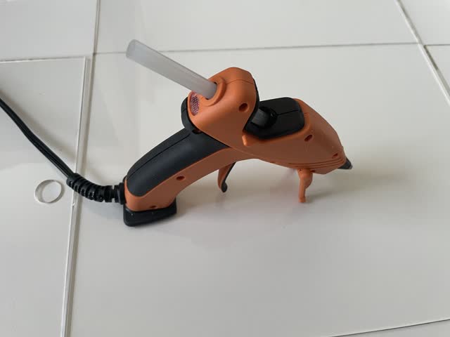
Here is the hot glue gun I used:
And here is me gluing it together!
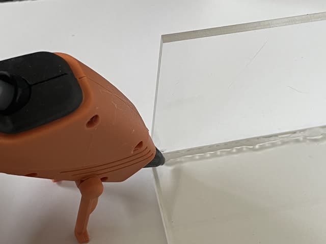
It worked totally great. One learning to note is that when assembling the first 2 sides (longer sides of the box), it would have been better not to glue all the way across (e.g. leave a little empty space at the ends). This way, when trying to fit/attach the smaller sides of the box which interface with the longer sides, they can fit properly into the space rather than be displaced by excess dried glue.
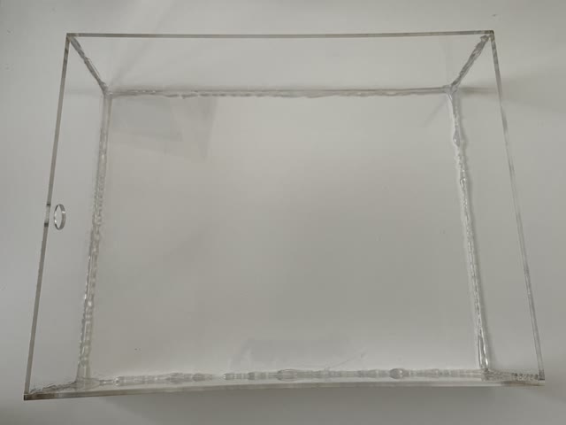
Hooray! It worked wonderfully. As you can see it's not beautiful looking now, however note that I intentionally only glued the inside parts of the box so that the outside will still be beautiful looking, especially after I paint the outside with acrylics!
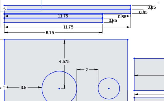
Then, I had an idea: what if I make the wooden op of the box sit perfectly on top of the clear acrylic by having small wooden sides to it? So, I made a laser cutting file for this purpose:
Here's the resulting laser-cut wood (12% speed / 75% power / 20Hz frequency):
Next, time to assemble the balsa wood top of the box and paint the box
Below is the assembled laser-cut box top (I used a hot glue gun for convenience; at this point, doing a press-fit design would have taken me too long):
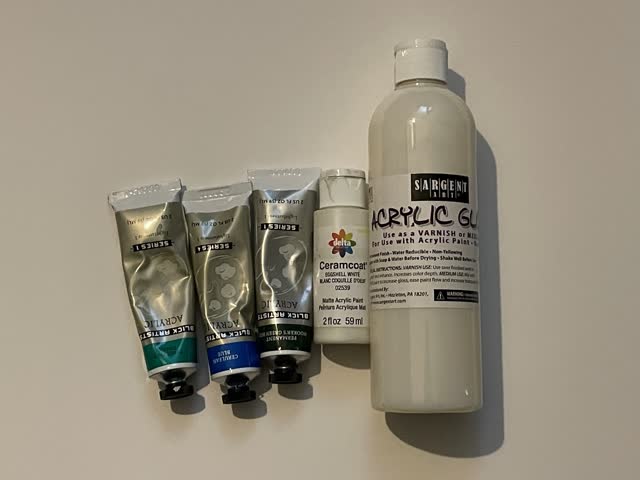
Here's the acrylic paints I used (bought from Blick art store in Boston, and the clear coat I got from Amazon):
Here is the top of the box after I painted it with the acrylic paints:

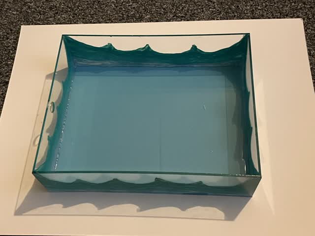
Here I painted the clear acrylic bottom of the box with nice turquoise waves!
Next, I worked on my code for the project. I connected the ESP32 (after fixing an accidental connection between 2 traces that wasn't supposed to be connected, and after placing the output pin correctly into GPIO 5 of the ESP32).
Then, TA Anthony Pennes helped me to to fix the code for the servo motor so that it would work well with high torque, for the ESP32:
Wiring for my final project:
Supplies (not including microSD-to-USB adapter, which I got from BestBuy):
Initial wiring for the speaker and SD card (note: I made. an error and forgot the GND that comes off the speaker):

Learnings For 3D Printing
While completing my final project, I learned more thoroughly how to use the different 3D printers! See below for my document
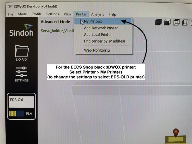
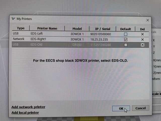
ed steps. It's important to select the right printer settings otherwise it will not let you print the file.
How to refill filaments on the architecture shop white 3D printers (3DWox1):
How to use the black 3D printer in the EECS shop:
Here was another progress update, as of Monday Dec 13, 12:30 AM:
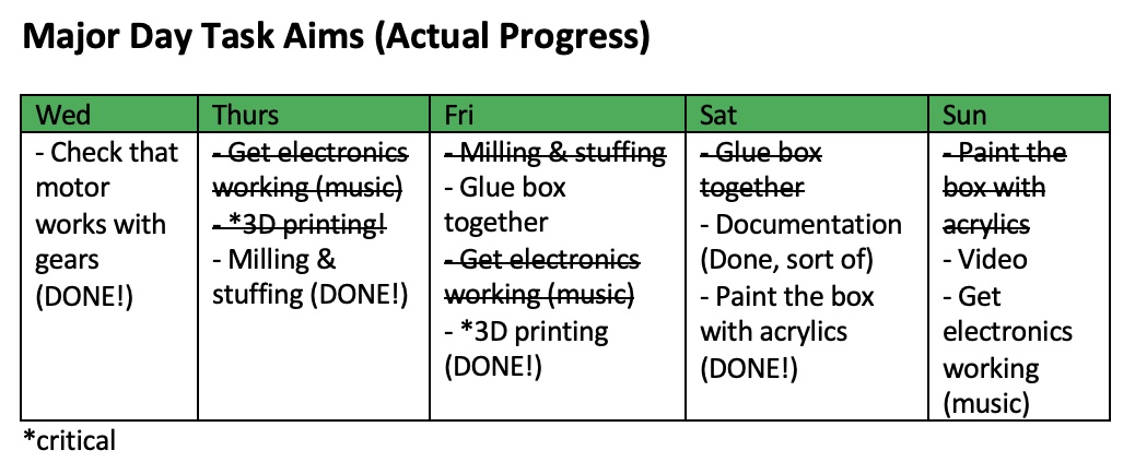
Although I didn't stick to. my schedule or Gannt chart of tasks perfectly, it certainly did help me get everything done by the deadline!!
For the electronics, I got quite stuck on how to play .wav or music files. The library in the tutorial doesn't work with ESP32, so I had to look up alternatives.
Also, I ran into an issue where the motor melted at the bottom!
Also, due to my wifi hotspot being 5G instead of lower GHz, I was unable to set up a wifi web app like I had wanted to. Here's how I wanted it to look. The code for my WebApp is at the bottom of this page.
So, lastly I made a Processing interface:

Processing & Arduino Code:
Arduino Code for the Processing GUI and control of motor:
int servo = 5;
int angle;
int pwm;
// define passive buzzer pin as ESP pin GPIO 32.
const int buzzer = 32;
// constants won't change. They're used here to set pin numbers:
//define the pushbutton pin (metal rugged on/off switch)
const int buttonPin = 26; // the number of the metal rugged pushbutton pin (GPIO 39)
// variables will change:
int buttonState = 0; // variable for reading the pushbutton status
int freq = 1000;
int channel = 0;
int resolution = 8;
void setup() {
pinMode(servo, OUTPUT);
Serial.begin(9600);
//initialize pushbutton pin as an input:
pinMode(buttonPin, INPUT);
ledcSetup(channel, freq, resolution);
ledcAttachPin(32, channel); // attach pin 32 to piezo buzzer.
// initialize the pushbutton pin as an input:
pinMode(buttonPin, INPUT);
//Set pin 27 as output (we will use it as a 3.3V source for the metal switch button)
pinMode(27,OUTPUT);
//pinMode(10, OUTPUT); //set pin as output , blue led
//pinMode(11, OUTPUT); //set pin as output , red led
//pinMode(12, OUTPUT); //set pin as output , yellow led
//Serial.begin(9600); //start serial communication @9600 bps
}
//int angle=90;
int timer=1500;
//timer=map(angle, 0,180,1000,2000);
void loop(){
digitalWrite(27,HIGH);
delay(1000);
ledcWrite(channel, 125); //2^8 / 2 = resolution / 2 = wave is half the time high, half low
ledcWriteTone(channel, 0); //silence the buzzer
// read the state of the pushbutton value:
buttonState = digitalRead(buttonPin);
if(Serial.available()){ //id data is available to read
char val = Serial.read();
if(val == 'w'){ //if r received
//turn on worktime (working session 50 min)
//ledcWriteTone(channel, 1500); //default the frequency to 2000
//if the metal on/off switch button is un-pressed then turn the motor the other direction
for (angle = 240; angle >= 0; angle -= 1) { // for (angle = 0; angle <= 140; angle += 5) {
// servoPulse(servo, angle); }
timer=map(angle, 0,180,1000,2000);
digitalWrite(5,HIGH);
delayMicroseconds(timer); //180 degrees is 2000, 0 degrees is 1,000
digitalWrite(5,LOW);
delayMicroseconds(20000-timer);
//20ms wave
}
}
if(val == 'b'){ //if b received
//turn on break time (10 min break)
ledcWriteTone(channel, 1200); //default the frequency to 2000
delay(1000);
ledcWriteTone(channel, 0);
//if the metal on/off button is pressed, then turn the motor a certain direction.
for (angle = 0; angle <= 240; angle += 1) { // for (angle = 0; angle <= 140; angle += 5) {
// servoPulse(servo, angle); }
timer=map(angle, 0,180,1000,2000);
digitalWrite(5,HIGH);
delayMicroseconds(timer); //180 degrees is 2000, 0 degrees is 1,000
digitalWrite(5,LOW);
delayMicroseconds(20000-timer);
//20ms wave
}
}
if(val == 'c'){ //if y received
//close the turtle box (turning motor right closes the mechanial iris)
//digitalWrite(11, HIGH); //turn on red led
//ledcWriteTone(channel, 1500); //default the frequency to 2000
//if the metal on/off switch button is un-pressed then turn the motor the other direction
for (angle = 240; angle >= 0; angle -= 1) { // for (angle = 0; angle <= 140; angle += 5) {
// servoPulse(servo, angle); }
timer=map(angle, 0,180,1000,2000);
digitalWrite(5,HIGH);
delayMicroseconds(timer); //180 degrees is 2000, 0 degrees is 1,000
digitalWrite(5,LOW);
delayMicroseconds(20000-timer);
//20ms wave
}
}
if(val == 'o'){ //if f received
//digitalWrite(11, LOW); //turn off all led
//digitalWrite(12, LOW);
//digitalWrite(10, LOW);
//open the turtle box (turning motor left opens the mechanial iris)
ledcWriteTone(channel, 1200); //default the frequency to 2000
delay(1000);
ledcWriteTone(channel, 0);
//if the metal on/off button is pressed, then turn the motor a certain direction.
for (angle = 0; angle <= 240; angle += 1) { // for (angle = 0; angle <= 140; angle += 5) {
// servoPulse(servo, angle); }
timer=map(angle, 0,180,1000,2000);
digitalWrite(5,HIGH);
delayMicroseconds(timer); //180 degrees is 2000, 0 degrees is 1,000
digitalWrite(5,LOW);
delayMicroseconds(20000-timer);
//20ms wave
}
}
}
}
Code for Processing Interface:
import controlP5.*; //import ControlP5 library
import processing.serial.*;
Serial port;
ControlP5 cp5; //create ControlP5 object
PFont font;
void setup(){ //same as arduino program
size(300, 450); //window size, (width, height)
printArray(Serial.list()); //prints all available serial ports
port = new Serial(this, "/dev/cu.usbserial-AR0K8897", 9600); //i have connected to /dev/cu.usbserial-14150. This will change depending on the port you are using.
//comment out the above line of code for port if I just want to see the interface without arduino running or board connected.
//lets add buton to empty window
cp5 = new ControlP5(this);
font = createFont("calibri light bold", 20); // custom fonts for buttons and title
cp5.addButton("worktime") //"red" is the name of button
.setPosition(100, 50) //x and y coordinates of upper left corner of button
.setSize(120, 70) //(width, height)
.setFont(font)
.setColorForeground(color(73, 121, 107)) //set both foreground & background color to set button color
.setColorBackground(color(73, 121, 107)) //set both foreground & background color to set button color
.setColorValue(color(0))
.setColorActive(color(0, 206, 209)); //color when you press the button
;
cp5.addButton("breaktime") //"yellow" is the name of button
.setPosition(100, 150) //x and y coordinates of upper left corner of button
.setSize(120, 70) //(width, height)
.setFont(font)
.setColorForeground(color(73, 121, 107)) //set both foreground & background color to set button color
.setColorBackground(color(73, 121, 107)) //set both foreground & background color to set button color
.setColorValue(color(0))
.setColorActive(color(0, 206, 209)); //color when you press the button
;
cp5.addButton("close") //"blue" is the name of button
.setPosition(100, 250) //x and y coordinates of upper left corner of button
.setSize(120, 70) //(width, height)
.setFont(font)
.setColorForeground(color(73, 121, 107)) //set both foreground & background color to set button color
.setColorBackground(color(73, 121, 107)) //set both foreground & background color to set button color
.setColorValue(color(0))
.setColorActive(color(0, 206, 209)); //color when you press the button
;
cp5.addButton("open") //"alloff" is the name of button
.setPosition(100, 350) //x and y coordinates of upper left corner of button
.setSize(120, 70) //(width, height)
.setFont(font)
.setColorForeground(color(73, 121, 107)) //set both foreground & background color to set button color
.setColorBackground(color(73, 121, 107)) //set both foreground & background color to set button color
.setColorValue(color(0))
.setColorActive(color(0, 206, 209)); //color when you press the button
;
}
void draw(){ //same as loop in arduino
background(255, 255, 255); // background color of window (r, g, b) or (0 to 255) where (255,255,255) is white
//lets give title to our window
fill(0, 0, 0); //text color (r, g, b) of the title, where (0,0,0) is Black
textFont(font);
text("Turtle Box", 110, 30); // ("text", x coordinate, y coordinate)
}
//lets add some functions to our buttons
//so whe you press any button, it sends perticular char over serial port
void worktime(){
port.write('w');
}
void breaktime(){
port.write('b');
}
void close(){
port.write('c');
}
void open(){
port.write('o');
}
Code for my Web App That Controls The Motor:
// Note: my phone hotspot won't work since it's 5GHz, and EECS_Labs wifi is only available in the EECS shop. Perhaps I could try MIT wifi if possible.
/*********
Rui Santos
Complete project details at https://randomnerdtutorials.com
*********/
// Load Wi-Fi library
#include <WiFi.h>
// Replace with your network credentials
const char* ssid = "EECS_Labs";
const char* password = "";
// Set web server port number to 80
WiFiServer server(80);
// Variable to store the HTTP request
String header;
// Auxiliar variables to store the current output state
String output26State = "off";
String output27State = "off";
// Assign output variables to GPIO pins
const int output26 = 26;
const int output27 = 27;
// Current time
unsigned long currentTime = millis();
// Previous time
unsigned long previousTime = 0;
// Define timeout time in milliseconds (example: 2000ms = 2s)
const long timeoutTime = 2000;
void setup() {
Serial.begin(115200);
// Initialize the output variables as outputs
pinMode(output26, OUTPUT);
pinMode(output27, OUTPUT);
// Set outputs to LOW
digitalWrite(output26, LOW);
digitalWrite(output27, LOW);
// Connect to Wi-Fi network with SSID and password
Serial.print("Connecting to ");
Serial.println(ssid);
WiFi.begin(ssid, password);
while (WiFi.status() != WL_CONNECTED) {
delay(500);
Serial.print(".");
}
// Print local IP address and start web server
Serial.println("");
Serial.println("WiFi connected.");
Serial.println("IP address: ");
Serial.println(WiFi.localIP());
server.begin();
}
void loop(){
WiFiClient client = server.available(); // Listen for incoming clients
if (client) { // If a new client connects,
currentTime = millis();
previousTime = currentTime;
Serial.println("New Client."); // print a message out in the serial port
String currentLine = ""; // make a String to hold incoming data from the client
while (client.connected() && currentTime - previousTime <= timeoutTime) { // loop while the client's connected
currentTime = millis();
if (client.available()) { // if there's bytes to read from the client,
char c = client.read(); // read a byte, then
Serial.write(c); // print it out the serial monitor
header += c;
if (c == '\n') { // if the byte is a newline character
// if the current line is blank, you got two newline characters in a row.
// that's the end of the client HTTP request, so send a response:
if (currentLine.length() == 0) {
// HTTP headers always start with a response code (e.g. HTTP/1.1 200 OK)
// and a content-type so the client knows what's coming, then a blank line:
client.println("HTTP/1.1 200 OK");
client.println("Content-type:text/html");
client.println("Connection: close");
client.println();
// turns the GPIOs on and off
if (header.indexOf("GET /26/on") >= 0) {
Serial.println("GPIO 26 on");
output26State = "on";
digitalWrite(output26, HIGH);
} else if (header.indexOf("GET /26/off") >= 0) {
Serial.println("GPIO 26 off");
output26State = "off";
digitalWrite(output26, LOW);
} else if (header.indexOf("GET /27/on") >= 0) {
Serial.println("GPIO 27 on");
output27State = "on";
digitalWrite(output27, HIGH);
} else if (header.indexOf("GET /27/off") >= 0) {
Serial.println("GPIO 27 off");
output27State = "off";
digitalWrite(output27, LOW);
}
// Display the HTML web page
client.println("<!DOCTYPE html><html>");
client.println("<head><meta name=\"viewport\" content=\"width=device-width, initial-scale=1\">");
client.println("<link rel=\"icon\" href=\"data:,\">");
// CSS to style the on/off buttons
// Feel free to change the background-color and font-size attributes to fit your preferences
client.println("<style>html { font-family: Helvetica; display: inline-block; margin: 0px auto; text-align: center;}");
client.println(".button { background-color: #4CAF50; border: none; color: white; padding: 16px 40px;");
client.println("text-decoration: none; font-size: 30px; margin: 2px; cursor: pointer;}");
client.println(".button2 {background-color: #555555;}</style></head>");
// Web Page Heading
client.println("<body><h1>Turtle Box: Time To Shellebrate!</h1>");
// Display current state, and ON/OFF buttons for GPIO 26
client.println("<p>50 min Work - " + output26State + "</p>");
// If the output26State is off, it displays the ON button
if (output26State=="off") {
client.println("<p><a href=\"/26/on\"><button class=\"button\">ON</button></a></p>");
} else {
client.println("<p><a href=\"/26/off\"><button class=\"button button2\">OFF</button></a></p>");
}
// Display current state, and ON/OFF buttons for GPIO 27
client.println("<p>10 min Break - " + output27State + "</p>");
// If the output27State is off, it displays the ON button
if (output27State=="off") {
client.println("<p><a href=\"/27/on\"><button class=\"button\">ON</button></a></p>");
} else {
client.println("<p><a href=\"/27/off\"><button class=\"button button2\">OFF</button></a></p>");
}
client.println("</body></html>");
// The HTTP response ends with another blank line
client.println();
// Break out of the while loop
break;
} else { // if you got a newline, then clear currentLine
currentLine = "";
}
} else if (c != '\r') { // if you got anything else but a carriage return character,
currentLine += c; // add it to the end of the currentLine
}
}
}
// Clear the header variable
header = "";
// Close the connection
client.stop();
Serial.println("Client disconnected.");
Serial.println("");
}
}

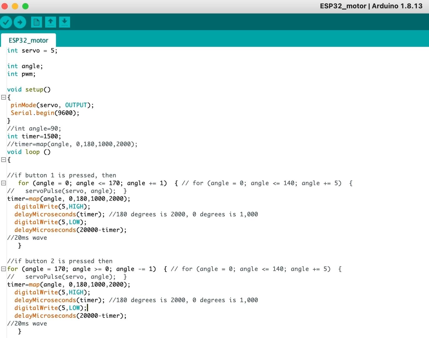
Code for motor and buzzer, controlled by button:
//Fab Academy 2020 - Fab Lab León
//Servo without library
//ESP32
int servo = 5;
int angle;
int pwm;
// define passive buzzer pin as ESP pin GPIO 32.
const int buzzer = 32;
// constants won't change. They're used here to set pin numbers:
//define the pushbutton pin (metal rugged on/off switch)
const int buttonPin = 26; // the number of the metal rugged pushbutton pin (GPIO 39)
// variables will change:
int buttonState = 0; // variable for reading the pushbutton status
int freq = 2000;
int channel = 0;
int resolution = 8;
void setup()
{
pinMode(servo, OUTPUT);
Serial.begin(9600);
//initialize pushbutton pin as an input:
pinMode(buttonPin, INPUT);
ledcSetup(channel, freq, resolution);
ledcAttachPin(32, channel); // attach pin 32 to piezo buzzer.
// initialize the pushbutton pin as an input:
pinMode(buttonPin, INPUT);
//Set pin 27 as output (we will use it as a 3.3V source for the metal switch button)
pinMode(27,OUTPUT);
}
//int angle=90;
int timer=1500;
//timer=map(angle, 0,180,1000,2000);
void loop() {
digitalWrite(27,HIGH);
delay(1000);
ledcWrite(channel, 125); //2^8 / 2 = resolution / 2 = wave is half the time high, half low
// ledcWriteTone(channel, 2000); //default the frequency to 2000
// read the state of the pushbutton value:
buttonState = digitalRead(buttonPin);
// check if the pushbutton is pressed. If it is, the buttonState is HIGH:
if (buttonState == LOW) //HIGH
{
ledcWriteTone(channel, 2000); //default the frequency to 2000
//if the metal on/off button is pressed, then turn the motor a certain direction.
for (angle = 0; angle <= 240; angle += 1) { // for (angle = 0; angle <= 140; angle += 5) {
// servoPulse(servo, angle); }
timer=map(angle, 0,180,1000,2000);
digitalWrite(5,HIGH);
delayMicroseconds(timer); //180 degrees is 2000, 0 degrees is 1,000
digitalWrite(5,LOW);
delayMicroseconds(20000-timer);
//20ms wave
}
} //del
else { //del
ledcWriteTone(channel, 1000); //default the frequency to 2000
//if the metal on/off switch button is un-pressed then turn the motor the other direction
for (angle = 240; angle >= 0; angle -= 1) { // for (angle = 0; angle <= 140; angle += 5) {
// servoPulse(servo, angle); }
timer=map(angle, 0,180,1000,2000);
digitalWrite(5,HIGH);
delayMicroseconds(timer); //180 degrees is 2000, 0 degrees is 1,000
digitalWrite(5,LOW);
delayMicroseconds(20000-timer);
//20ms wave
}
// read the state of the pushbutton value:
buttonState = digitalRead(buttonPin);
}
// delay(1000);
// ledcWriteTone(channel, 1000); // change to lower pitch note
// delay(1000);
// ledcWriteTone(channel, 1300);
// delay(1000);
}
I will be searching for jobs after graduating from MIT. View my skillsets list if you would like to know what knowledge and skills I have gained from this course.
created with
Website Builder Software .