My inspiration for this project was a youtube video of a custom-made mechanical iris lock box.
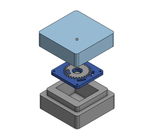
First, I sketched my ideas with pencil and paper. See below for my initial sketch. It includes a wooden top (with engraved initials), wooden bottom (with a raised section near the middle), metal sheet with a hole cutout, gears and gear components, and a heart-shaped key.
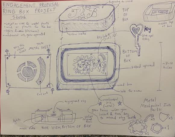
When the key is inserted into the smaller gear and turned, this will cause the larger gear will rotate. This, in turn, will cause the inner curved beams to move, pulling the inner "petals" outward/inward to show the engagement ring or to hide it from view. Objects can be contained on the inside of the wooden bottom, secured by a foam holder covered in velvet fabric. The inside of the box will contain electronics that allow music to be played and a ring of lights to be turned on whenever the key is turned, illuminating the ring to make it sparkle.
Below are a list of possible ways I might fabricate my design. However, I still haven't decided what type of wood or what type of metal to use! Perhaps Poplar Wood & Aluminum?
Since I have worked in the medical industry for 2 yrs and plan to return there after graduating from MIT, I decided to choose OnShape as my primary 3D CAD software. This software works almost exactly the same as Solidworks (which is the golden standard software in my industry), except that it has better rendering & visualization capabilities and more seamless team editing version control capabilities. I've seen increased usage of OnShape in my field. so I have chosen to use it for this class since I believe it will one day replace SOLIDWORKS as the new standard CAD software in my industry.
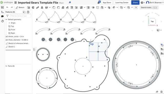 My first step was to import the existing Etsy .dxf 2D vector file template into the OnShape software. I used this .dxf file as template geometry to help me make my own new sketch file from scratch in OnShape, setting variables for the dimensions to make the design iteration process easier and to allow future users to more easily adapt my design to their needs.
TIP: import a .dxf file! I tried importing other file types and had issues viewing them in OnShape, so don't make the same mistake as I did!
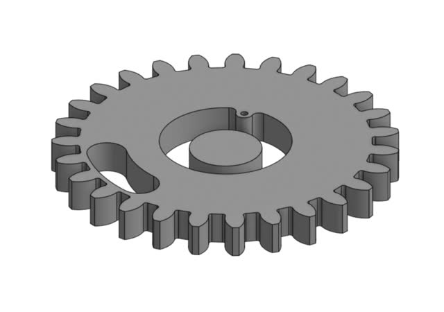
Upon loading the template file I realized I need to start making my own from scratch since there are modifications I need, and I want my files to be easy for others to modify as well. My first step to recreate the main gear on the right was to work from a public OnShape gea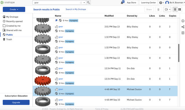 r template and customize it.
Next, you can make geometry such as that shown in my examples near the bottom of this page, to modify the gear. Some useful tools to experiment with, that I used to make this design, are:
If you can't find a particular icon/button for a tool, just use the grey-colored search tools (Option+c) box in the upper right hand corner of OnShape.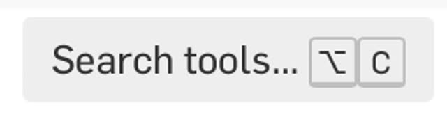
Next, click the green checkbox in the "Sketch 4" popup box at the left. This will exit sketch mode.
IMPORTANT: Make sure to set variables for your dimensions, to make the drawing parametric! This really comes in handy later for when you want to easily change around your design's dimensions. :)
To set variables in OnShape:
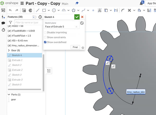
In the interest of time, I am unable to detail the exact step-by-step process in which I created my design. However, I have included screenshots below of the geometries I created prior to using the Trim tool to delete lines or parts of circles to result in the sketch cutout shapes that I wanted.

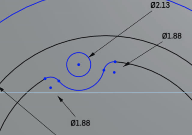

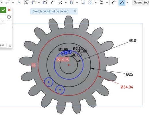


The first 2 photos show how I used the dimension tool and setting variables to make the two smallest circles the same size. I used the Tangent tool to make them touch the circumferences of the other circles, and the Trim tool to remove lines.
I used dimension tool to set variables so that the two small circles are the same exact size (type in # instead of typing in a dimension value, scroll to the bottom "add new variable", and then name the variable and add a value to it. Then, at the next created circle, use the dimension tool and type in #, selecting your newly created variable!)
The bottom left picture shows usage of the tangent tool (symbol in the upper right) to make the circles touch. The bottom middle picture shows usage of the trim (scissors) tool to remove lines. The bottom right picture shows how the part looks when I have clicked the green checkmark (exit sketch mode).
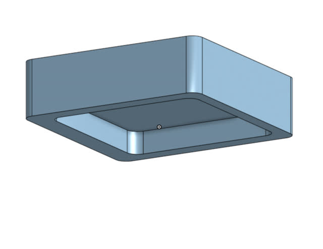
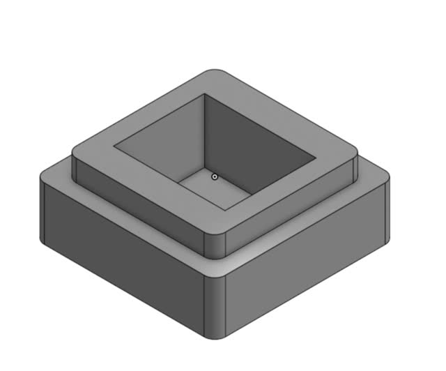
To make the CAD parts for the top, bottom, and metal sheet, I used the following tools in addition to the ones described above:
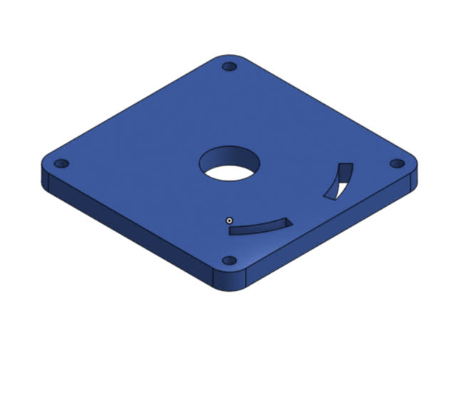
My final CAD file:
A very noteworthy tip (which I found through trial, error, and mistake) is that OnShape makes assemblies easy. Instead of having to create a separate Master Sketch for top-down assembly, you can just simply start by creating your first part and using variables for the dimensions. Then, just hover to the right of the Part in the Parts List in the lower left, and you should see a little eye symbol show up to the right. Click on it, and that will then hide the part from view. Miraculously, if you then proceed to make a new sketch in the same window, nothing appears to change in the parts list... but as soon as you extrude your next sketch, a new Part (Part 2!) will show up in the bottom parts list! Now you can just hide and unhide as desired; whenever you hide all the parts, it will start creating a new part with whatever new sketch + extrusion that you are working on.
To make an assembly, jsut right-click the Parts Studio tab at the bottom to choose Assembly from the options that show up.
Similarly, to make a drawwing, just right-click on the Assembly tab at the bottom and Create Drawing.
Super easy! :)
From this I learned a LOT more about the Coincident, Tangent, and Variable Dimension tools/options in OnShape. I also (by trial and error) learned how to make a parts studio and assembly using a top-down master sketch technique, which ended up being much easier in OnShape than in Solidworks! For more advanced applications, I plan to further work on the gear and the complicated heart-shaped key for this CAD model, which may involve using reference geometry or 3D manipulations like Sweep and Revolve.
created with
Website Builder Software .