
Above is a video of a servo motor (4.8-6V, ~1.3kg torque) being controlled by my PCB board, which was boot-loaded with the capability to use Arduino IDE software for programming.
The assignment for this week was to add an output device to a microcontroller board I designed, and program it to do something.
So, this week I decided to connect a lower-voltage motor (H-King HK SCM 16, 6V, single chip digital motor). This motor works with voltage anywhere between 4.8V - 6V, so the 5V powered from my existing PCB board worked just fine. Below are a few additional specs for the motor:
HKSCM16-6 Single Chip Digital Servo (6V)
Spec.
Torque: 1.3kg @ 4.8v, 1.5kg @ 6v
Weight: 16g
Speed: 0.23 / 60deg @ 4.8v, 0.19 / 60 deg @ 6v
Voltage: 4.8v~6v
Plug: JR
Gear Material: Plastic
Type: Digital
Motor: Brushed
Spline: 20
I don't know yet whether the torque in the force but this motor applies is sufficient for my final project, but I suspect it might possibly be within the right range. In the case that it is not strong enough to power my final project, I will need to remake my PCB board with an external power source. For example, a 9 V or 12 V external power source or external battery which then connects to a footprint trace on my board that then connect on its own as a new trace line around the board to supply that power. If I want to, I could add additional regulators to the board so that the 9 V or 12 V power converts to 5 V or 3.3 V to supply power to the microcontroller and the button.
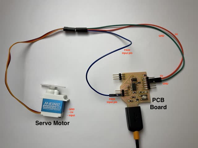
The motor has three different lines, one for power (VCC), one for ground (GND), and one for digital pulse width modulation input (analog pulse width modulation input also would work). For the input, this means connecting one of the appropriate pins on the microcontroller via traces, and connectors, to the motor VCC wire. Below is a diagram of how I connected the motor to my PCB board.
Below is the Arduino IDE code I used to control the servo motor:

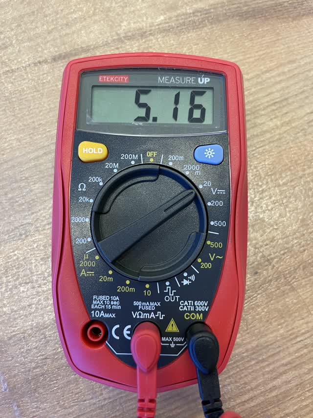
The group project for this week was to measure the power consumption of an output device. To do this, I used a multimeter on different settings (voltage setting, current setting) to measure the voltage and to measure the current supply to the motor, while the PCB board was plugged into the power source. Specifically, I connected one of the multimeter wires to GND of the motor and the other wire to VCC of the motor. Below are the values that I read from the multimeter as well as images of how I measured these values:
For measuring voltage:
(I measured 5.16 V)
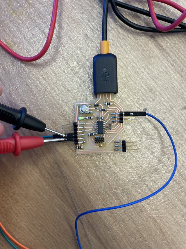
For measuring current:
(I measured 0.05 Amps)


Power Calculation:
For the Amp & Volts values I got, the power is P = I * V = 0.05 Amps * 5.16V = = 0.258 Watts (which TA Anthony says is on the low side for this servo motor)
However, on a different (higher quality) multimeter, the current fluctuates more in actuality as the motor receives pulses. The fluctuations went up to 0.5 Amps.
Thus, the power is P = I * V = 0.5 Amps * 5.16V = 2.58 Watts (which TA Anthony said is more reasonable for this servo motor)
Learnings / Advanced Applications:
Learnings:
Advanced Applications:
created with
Website Builder Software .