
First, I made my design in OnShape (made a Parts Studio), with document units set as Inches. I used the Mirror tool quite often for copying and pasting the slots in my design!!
Then, I made a drawing in OnShape from the Parts Studio and moved my stuff to the side away from the drawing template background area. I exported to .dxf. Note that I had to click the + button to create a drawing from the parts studio, and use a 1:1 ratio when inserting the parts studio into the drawing. I also had to insert the parts away from the default drawing background, which I deleted later after importing the file in Rhino.
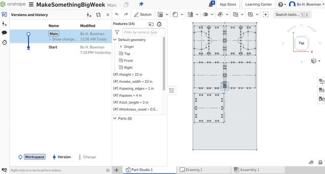
Exporting the CAD drawing to .dxf in OnShape:

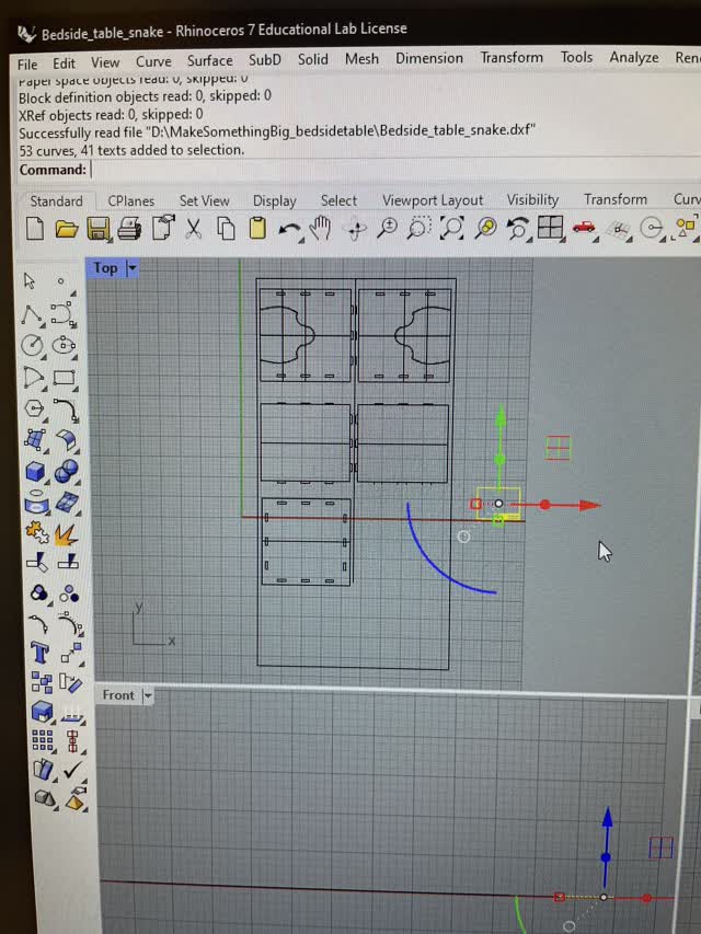
Next, I used a USB to bring my file to an N51 MIT Shop Computer. Then I opened the file in Rhino, using units as Inches when importing.

Here, these images show me deleting the OnShape drawing document background to the right.
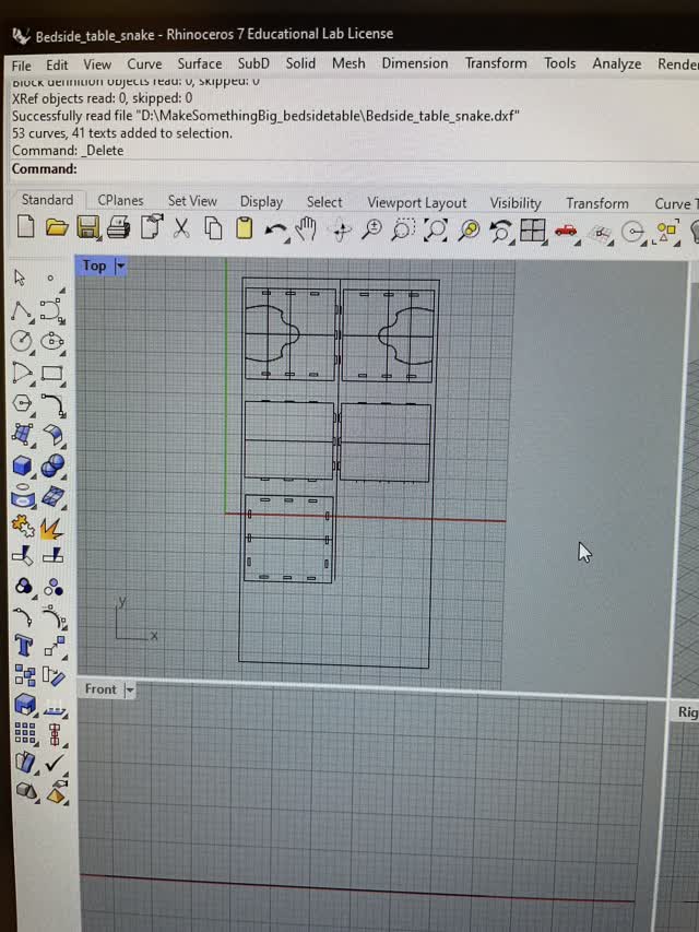
All gone! :)
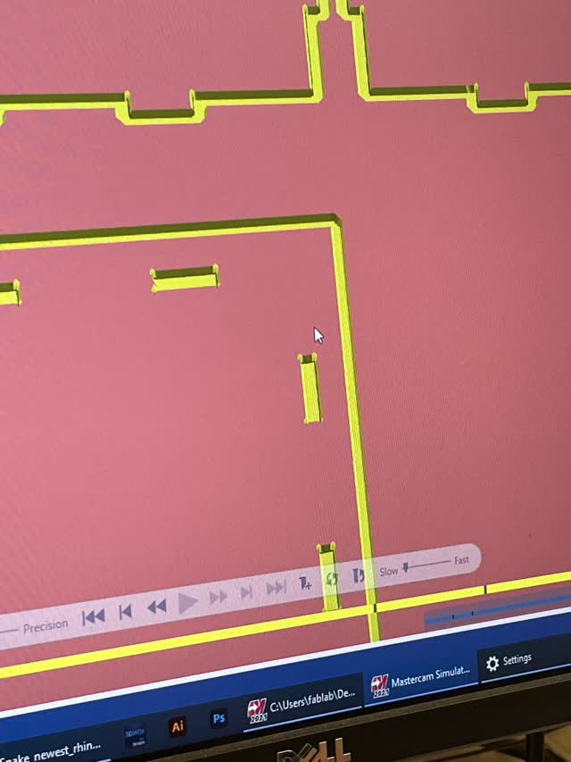
After much back-and-forth with Chris, who was helping in the N51 shop, together we edited the file in Rhino and then in MasterCAD to get it ready for milling the 48x96" ORB wood board. Here are some of the steps for preparing the file for billing on the equipment:
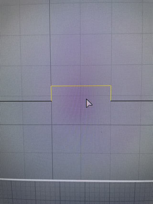
When loading into MasterCAM, do the following: ctrl A, delete, File > Merge > select your rhino file, clickthe green checkbox, and select the Mortices. Note that levels in MasterCAM are equivalent to layers in Rhino.
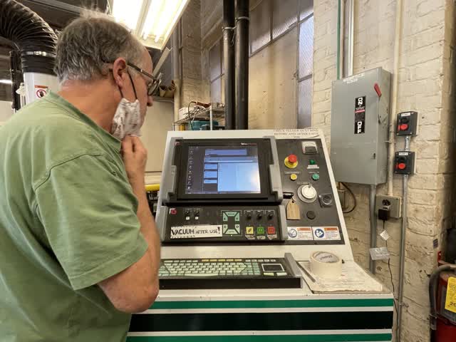
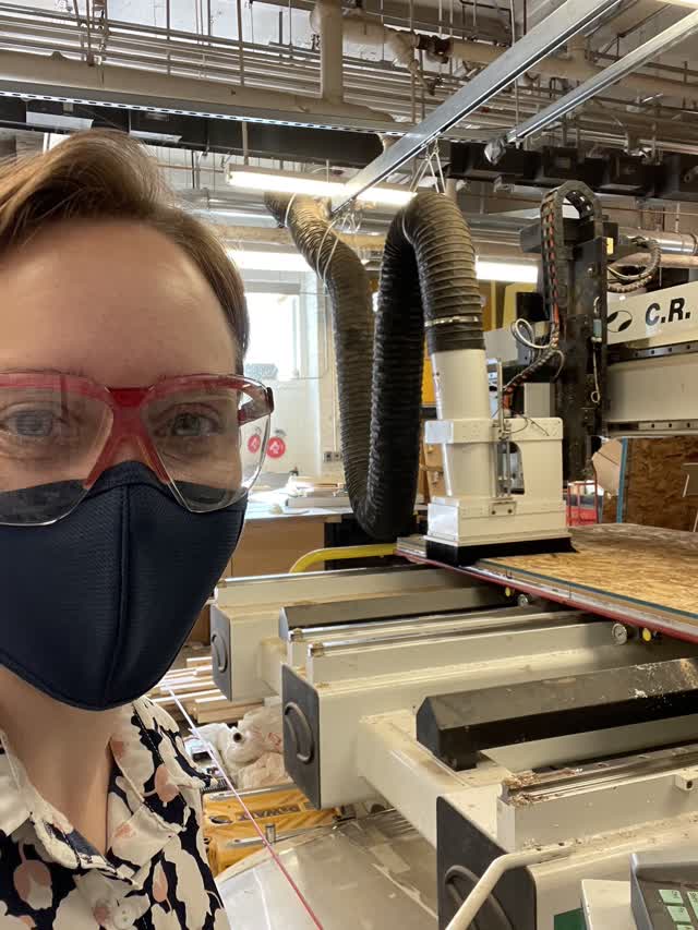
After modifying the file and preparing it for the equipment, with the help of Chris we loaded the file and milled the board of wood on the C.R. Onsrud equipment. Also, note that I put the wood finished side down onto the equipment bed.
1) Load the file with USB
2) Press Stop and Drives On
3) Use the yellow buttons on the side of the equipment to position the wood and use vacuum to keep it in place during the milling
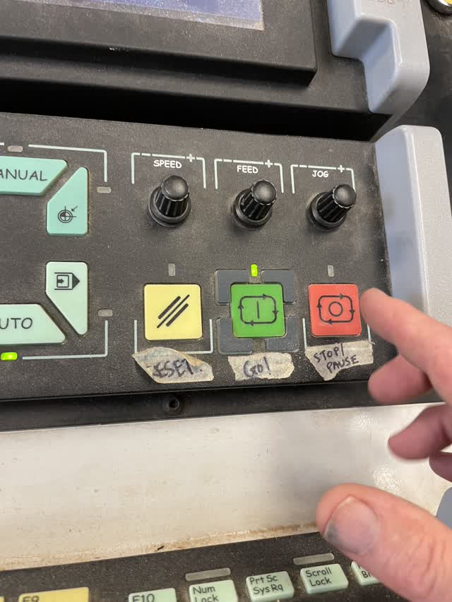
4) Lastly, I sat next to the controls with my hand near the stop/pause button to be ready to stop it if anything had happened during the milling (note: if you use the wrong milling too e.g. use a drill instead of an end-mill to cut sideways, this can cause a fire to happen!
Below is an image of the two different types of tools - an end mill versus a drill. If you use a drill for sideways cutting, this can cause fires so it's important to know which tool to use. In my case, I used an end mill because I was cutting out lines, not just holes. Since the ORB wood is a half inch, I used a quarter inch dept x 2 to cut a half inch into the material.

Next, I used several tools to re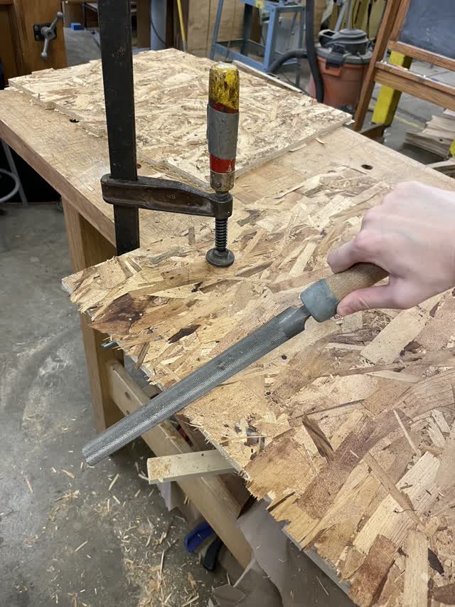 move excess pieces of wood from my parts. I learned that I need to hold the wood with a clamp and use both hands or one hand to push the file tool in the same direction each time. I also learned that I should push the file downward as I am moving it diagonally. Before I was doing all this wrong, I was using the file in both directions and the edges were still very rough. After learning the right technique the edges were smoother rather than with splinters, and the process of using the file tool was much faster too.
For the inner edges of the slots, are used a smaller tool that could get into the holes.
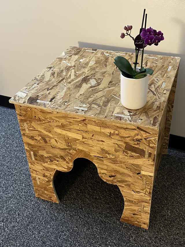
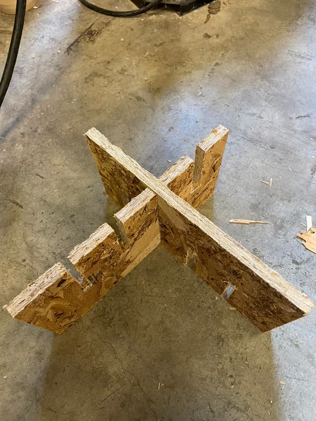
Finally, I brought the wood pieces home and assembled the table. Note that I had to spend a lot of time in the shop to sand down different parts and check that they were going to fit together when I got home. When I completed the final assembly, I was happy to find that the parts fit together perfectly and that my design worked well. However, the table turned out much larger than I expected and so in the future I would be much more conservative about the dimensions and try to underestimate lengths and widths rather than overestimate them.
I bought several blue paints but ran out of time to paint my table. However I plan to do so in the coming weeks with several types of blue acrylic paint.
My final assembled table (unpainted):
For the group project, Emily from my group kindly added a CAD file with slots to her ORB milling for the week. Each of the slots is a different size based on the milling input on the computer.
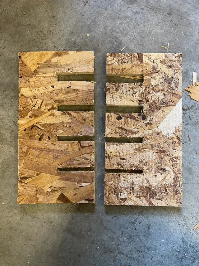

The second-to-largest slot worked the best for a press-fit connection. 0.5in worked the best.
Unfortunately, I ran out of time to test runout, alignment, speeds, feeds, materials, and toolpaths for the machine, since I'm still catching up on last week's board milling (still having major difficulties with exporting the files properly to have a board to program).
created with
Website Builder Software .