
This week, the assignment was to measure something: add a sensor to a microcontroller board that you have designed and to read it.
Here are the input devices I plan to try:
Looking forward, I plan to try using the following output devices for my final project and for next week:
Let's take another look at the diagram for the SAMD11C microcontroller I'm using:
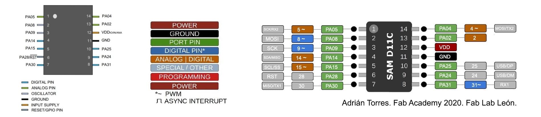
PA05, PA04, PA02 = analog (or digital), PWM
PA08, PA09 = digital (*with PWM)
PA14, PA15 = analog (or digital), PWM
So, it seems likely that I will have enough pins for my project.
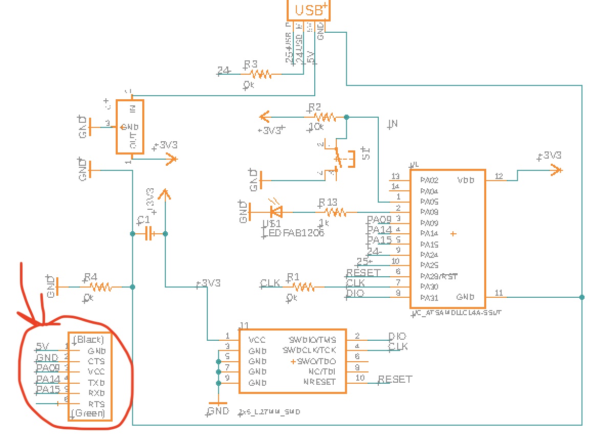
Thus, knowing that I might need to swap out different input & output devices in the coming weeks, I decided to design my board so that instead of connecting these parts to the board itself, I plan to instead connect the pins and 5V, 3.3V, and GND to 6-pin or 3-pin FTDI headers. In the software, I used CONN_06_FTDI-SMD-HEADER (6 pins, FTDI header) and SW_SPDTSWITCH (3-pins, same size as the 6-pin header; I won't be using an actual switch but the footprint is what I needed). Below, I added the 6-pin header.
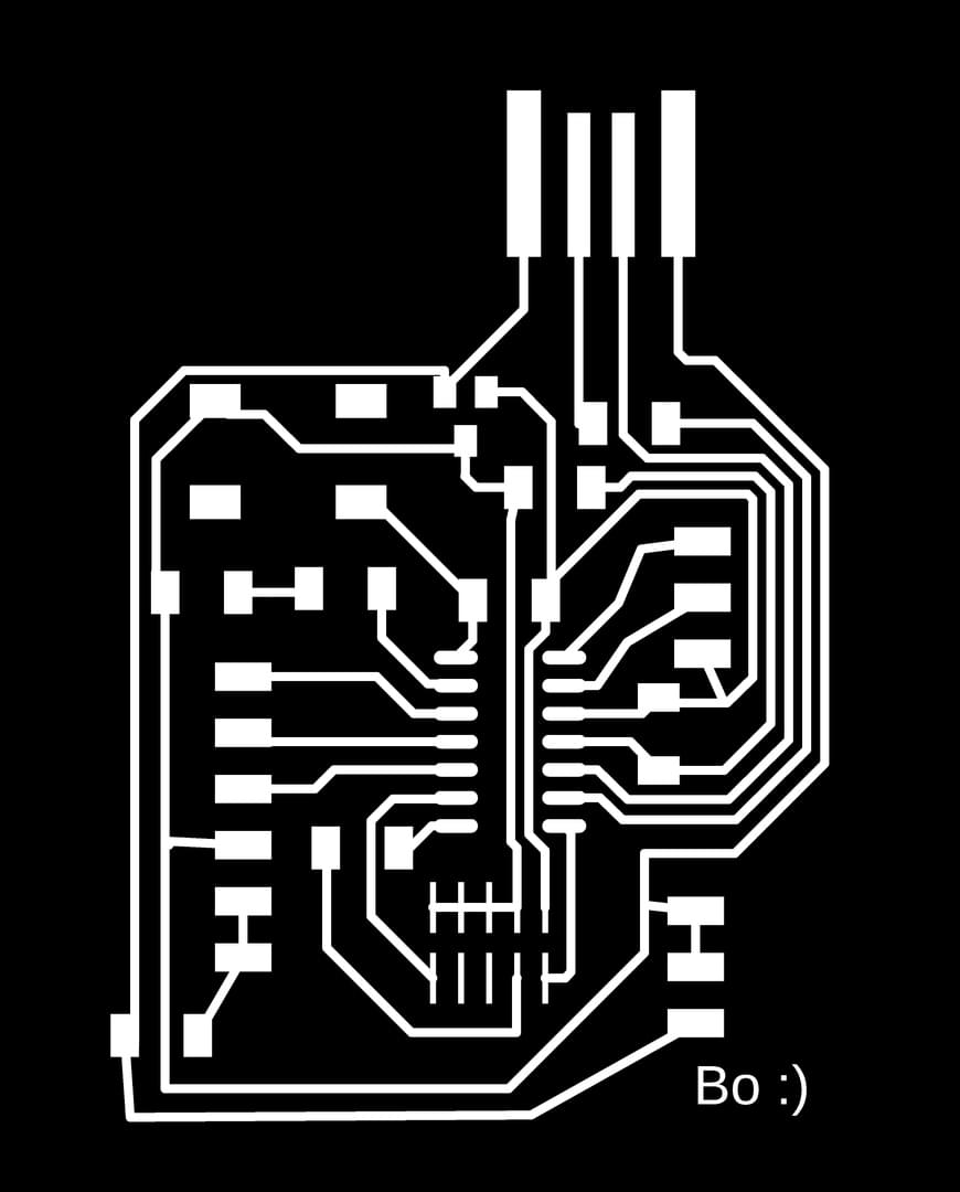
And below is the PCB document for the above schematic:
Next, I added the rest of the headers:

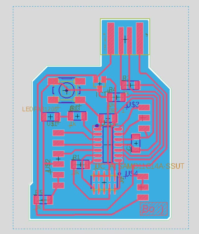
And here is the resulting PCB document:

After that, I added a polygon and edited the Dimension and Bottom layers appropriately:
Next I exported PNG monochrome (black & white) files for milling:

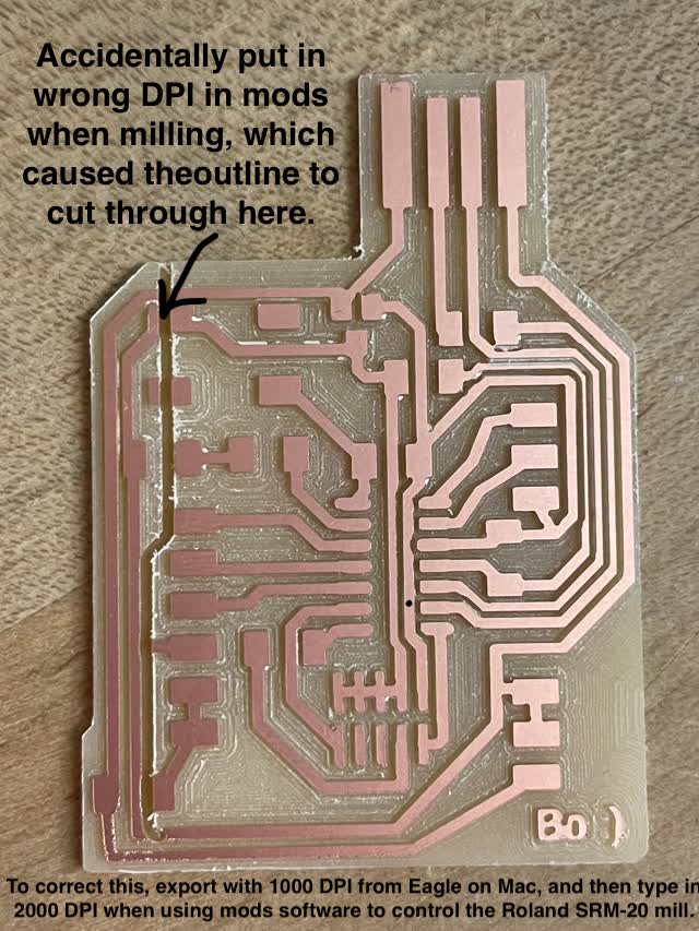
oops! Made some mistakes:

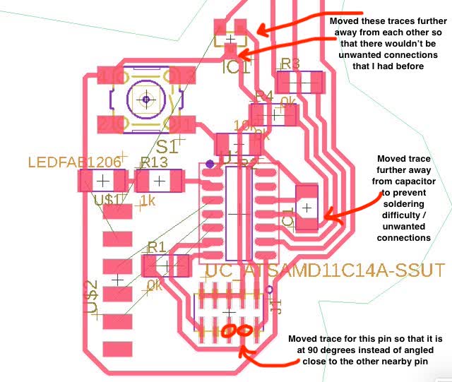
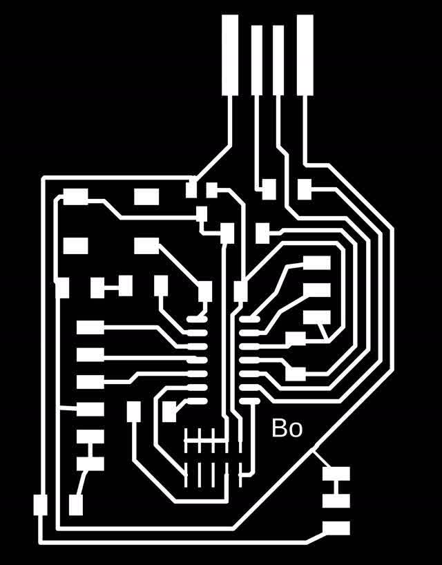
So then I re-did the milling one more time with a slightly different PCB board routing layout to allow for more spacing:
0.4064 is the line width for routing.

Here are the resulting PNG files (you can see the traces are more spaced out this time, hopefully that will help during milling):

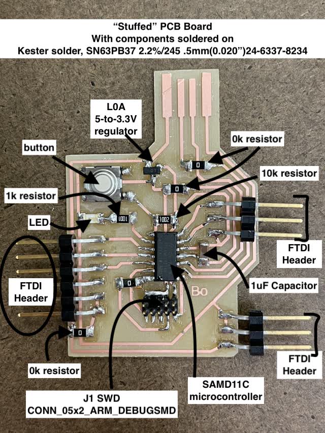
Hooray! Now my board has been milled again, this time without overlapping traces, and I made the outline closer to the footprint pads for the FTDI headers so thatI can get easy access to those headers to plug in input/output devices after soldering:

Yay! Now it's time to solder the components onto the board:
Next, I taped a square of cardboard to the back of the USB connection part of the PCB board:

Here's the temperature I soldered at (69 deg F):

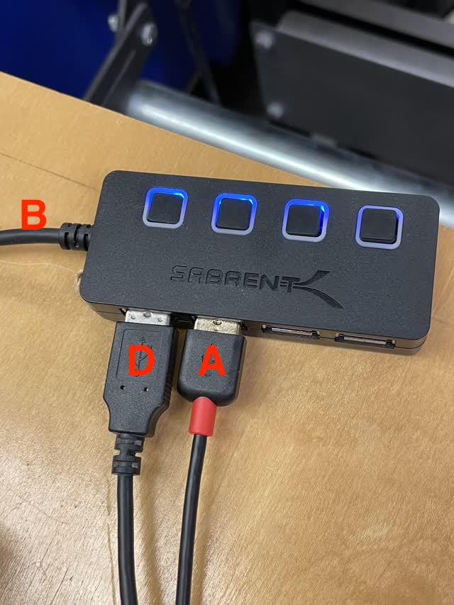
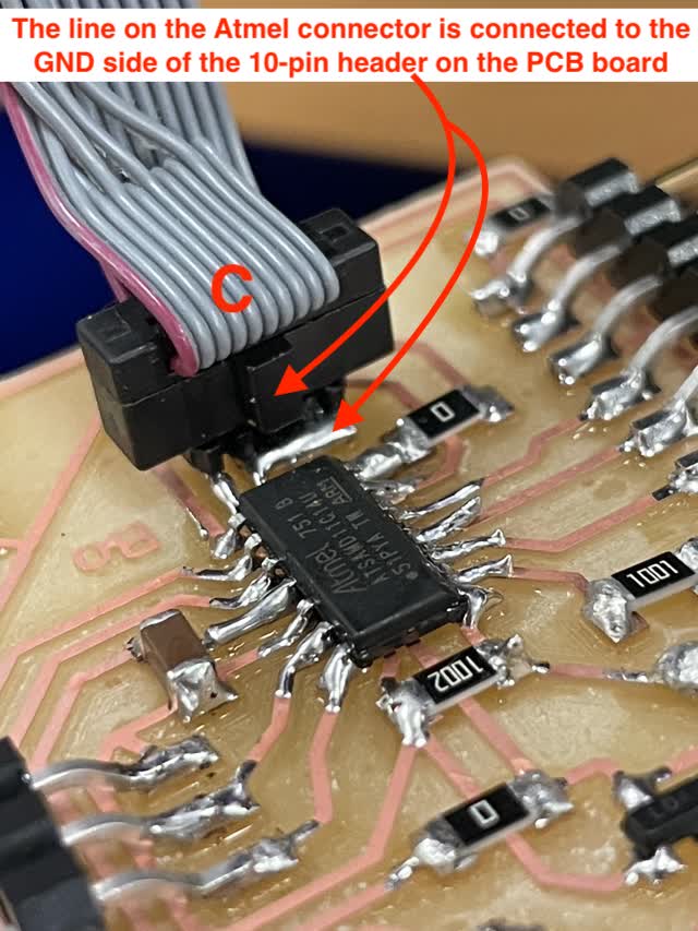
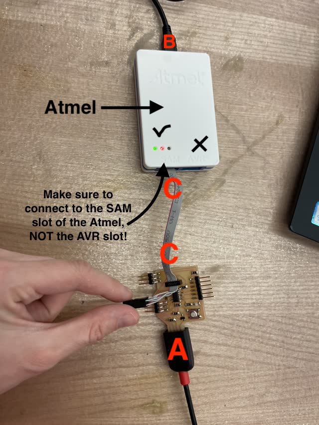
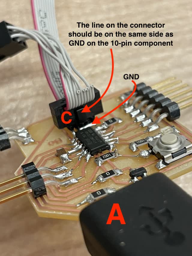
Next, I tried to bootload, by connecting in the following way:


Then I navigated to Downloads/edbg within the archshop computer near the solder stations, using cd, ls, and cd ../ commands in the Terminal command line on the computer.
Next, I typed into the terminal the following code:
./ edbg -b -t samd11 -pv -f sam_ba_Generic_D11C14A_SAMD11C14A.bin
Unfortunately, I got errors!

The errors above were because connection C in the Atmel photos above was in the wrong slot! It was in the AVR not the SAM slot.I should have put connector C into the SAM slot of the Atmel!!!
How to Bootload on your laptop with the Atmel:
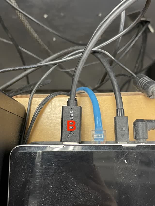
First, connect the Atmel to your laptop as follows. Connect Atmel to your computer and connect USB from your board to your computer. Remember to use the SAM connector slot on the Atmel, NOT the AVR slot.

Connect to Generic D11C14A under Tools > Board in the Arduino software. If it doesn't show up, that means you need to add the D11C library. Go to the URL below to section 3 (Arduino Setup) and follow the directions to add the library.
https://mtm.cba.mit.edu/2021/2021-10_microcontroller-primer/fab-arduino/#3-arduino-setup
Next, in the Arduino IDE software settings under Tools etc., go through and make sure the following settings are selected:
Clock source: Internal_USB_Calibrated_Oscillator (careful when picking otherwise you may ruin your board!)
USB Config: CDC_ONLY
Serial Config: ONE_UART_ONE_WIRE_NO_SPI
Bootloader Size: 4KB_BOOTLOADER
Timer PWM Frequency: 732.4Hz (16-bit)
Programmer: Atmel SAM-ICE
Click on Burn Bootloader
Now, the board can be detected under Port.
To try a simple Arduino Button LED program after bootloading :
1) Under Tools > Port, in the Arduino software, connect the Port to Generic D11C14A (if you're having trouble, use this type of connector for USB; most others will not work!!)
https://www.amazon.com/gp/product/B00N9HRTFU/ref=ppx_yo_dt_b_search_asin_title?ie=UTF8&psc=1
2) Under Tools > Board, select Generic D11C14A
3) File > Examples > 02.Digital > Button, to open an example button-turning-on-LED-sketch.
4) Edit the initial code as follows (change buttonPin to 5, representing PA05 on the SAMD11C microcontroller which the button is connected/soldered to, and change int ledPin to 8, representing PA08 on the SAMD11C microcontroller which the LED and resistor is connected/soldered to.
// constants won't change. They're used here to set pin numbers:
const int buttonPin = 5; // the number of the pushbutton pin
const int ledPin = 8; // the number of the LED pin
5) Click the checkmark icon, wait, and then click the right arrow button (Upload button in Arduino software, in the upper left hand corner)
5) Now, the LED turns on/off when you press on the button on the board! :)
Unfortunately the sketch uploaded properly, however the LED did not blink. With Anthony (TA) help, with a multimeter, I discovered that I had put the LED the wrong way! The small green stripe along the length of the LED should point toward GND, not toward the pin!
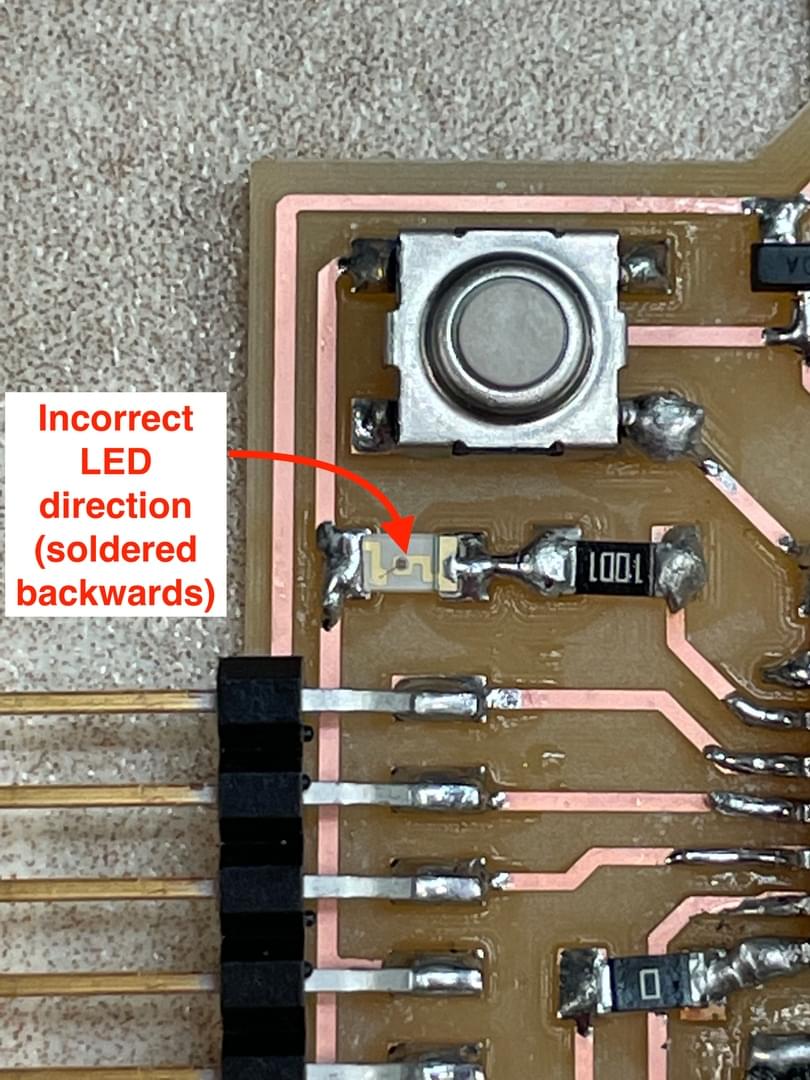

Hooray, now it works!
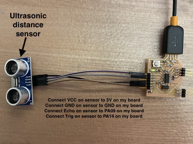
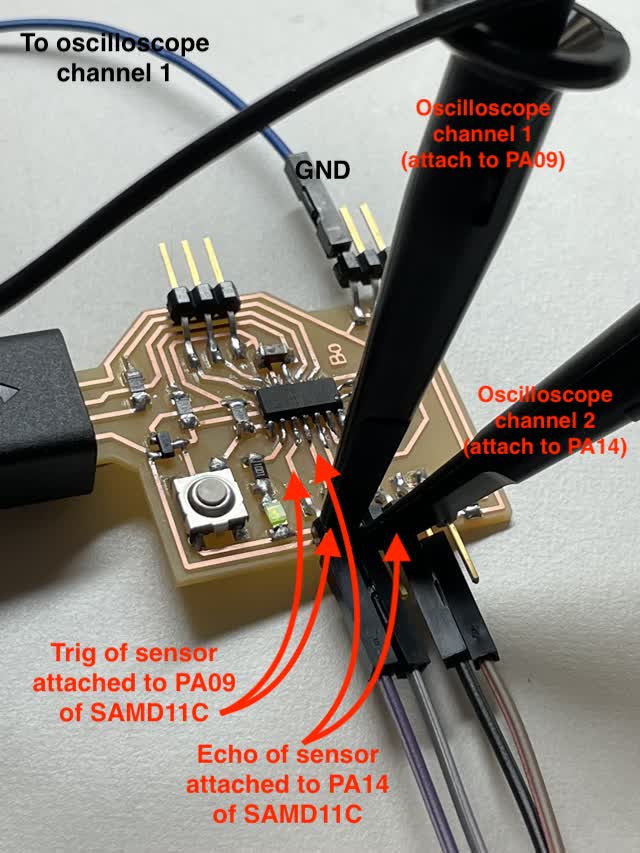
Next, I uploaded a Sketch for the ultrasonic sensor, and connected the ultrasonic sensor:
GND to GND
VCC to 5V
Echo to PA09
Trig to PA14
Here's the code that I uploaded. Note that I changed the code at the top so that trigPin is connected to pin14 (PA14) and echoPin is connected to pin 9 (PA09), as per my PCB design from Eagle.
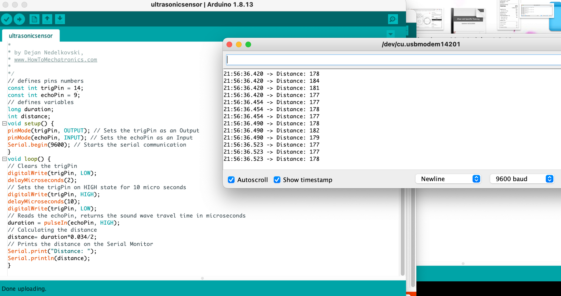
As you can see above, I was able to sense different distances in the Serial Monitor when waving my hand across the ultrasonic distance sensor! :)
Note: scroll down further for Group Project section.
General learnings:
How to export PNG files from a routed PCB document made from a schematic:
More advanced applications:
Mistakes from this week:
The group assignment for this week is to probe an input device's analog levels and digital signals.
Input devices, for example a button, can have digital signals (on/off, 0 or 1, connected or disconnected)
Analog input devices, for example an ultrasonic distance sensor, can take a range of values.
When probing on the oscilloscope, you can read differences in the digital or analog signals by looking at the oscilloscope waves.

To probe digital input device (button) with oscilloscope:
1) Plug in the ultrasonic sensor to my PCB board by connecting to the appropriate pins (as described above for the individual assignment)
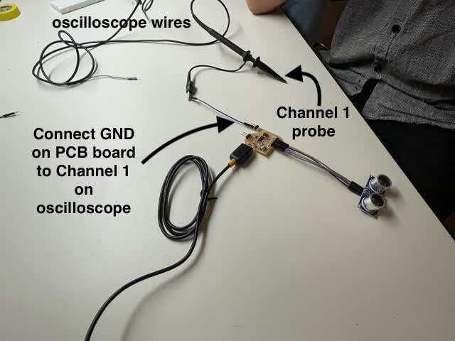
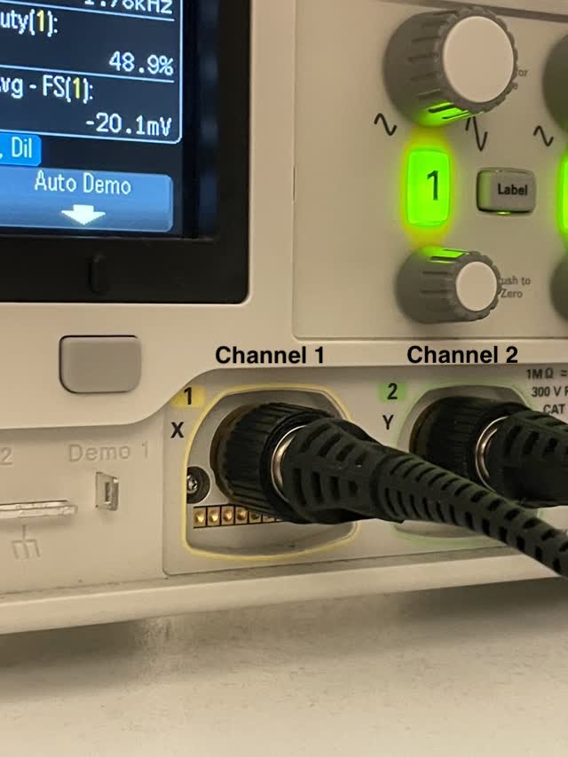
2) Plug GND on my board into the oscilloscope channel 1, as shown below
3) Change oscilloscope to Trigger mode
4) Select Single Shot mode on the oscilloscope
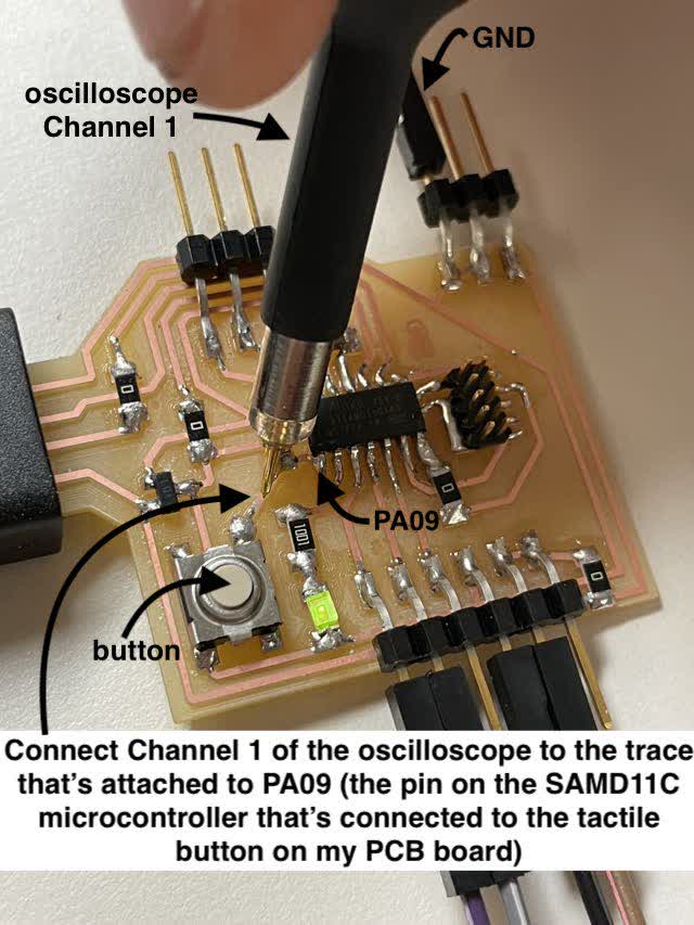
5) Connect the tip of the Channel 1 probe to the pin trace on the board that's connected to the button (in my case, it was PA05 on the SAMD11C)
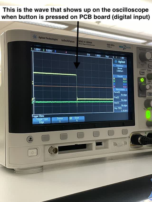
6) Check the oscilloscope wave on the screen. Press the button on the board (on and off) and see the difference in the wave on the screen. You'll notice that a wave shows up for the button press.
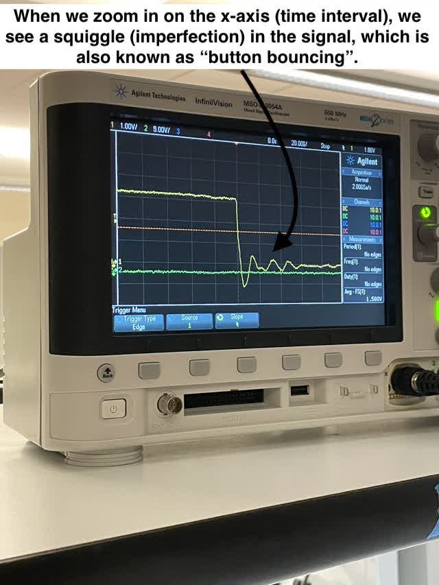
7) Zoom in with better time resolution (make the x-axis tick marks farther apart, decreasing the time on the x-axis, to see it zoomed in). You'll notice that the wave no longer looks quite as clean. This squiggle wave is called "button bouncing"; ideally a button would show a nice clean square wave, but in reality sometimes the signal isn't perfect, hence the "button bouncing" squiggle wave.
To probe analog input device (ultrasonic distance sensor) with oscilloscope:
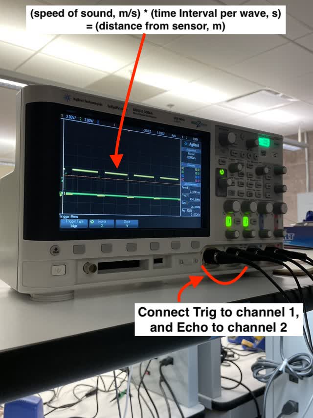
For this part of the assignment, you can connect one channel to Trig and one to Echo, and then observe the difference between the time waves.
1) First, with the GND still connected as per above, connect as follows:
Channel 1 connected to the 3rd pin down (PA09)
Channel 2 connected to the 4th pin (PA14)
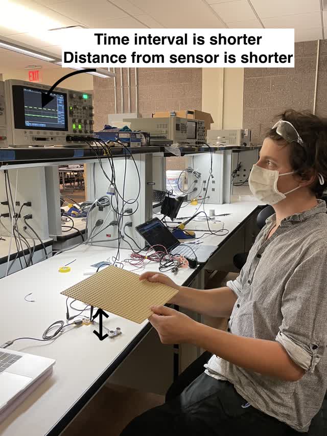
2) Now, check the wave on the screen. TA Anthony took a lego sheet and held it in front of the ultrasonic sensor, moving it up and down, and we were able to see a difference in the waves on the screen.
What distance does sound travel from the sensor to the lego sheet and back?
We did a calculation:
c*t = d
(speed of sound) * (time it takes to get here) = (total distance from the sensor to the lego sheet and back, in meters)
c = speed of sound
t = time it takes sound to travel from the sensor to the lego sheet and back
d = distance from the sensor to the lego sheet and back, in meters
The time, which we read from the oscilloscope wave, is about 2 milliseconds.
(343 m / s) * 2 milliseconds = 0.6 meters
This is approximately 2 feet, which checks out, since TA Anthony was indeed holding the lego sheet about 2 feet away from the sensor! :)
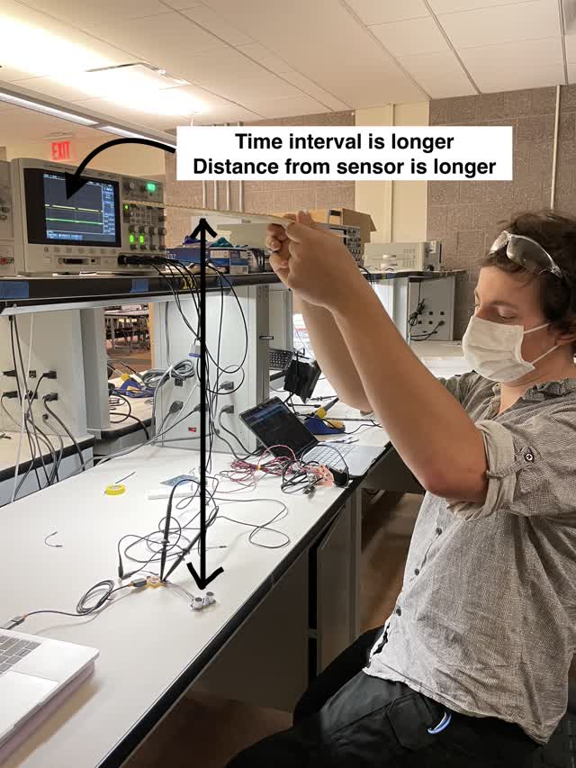
We can also see when Anthony moved the lego sheet further away from the sensor, the time interval for the waves was longer, whereas when he moved the lego sheet closer towards the sensor, the time interval for the waves was much shorter. This makes sense, because based on the formula, shorter distance means shorter time interval, and longer distance (meters) means longer time interval (milliseconds). Yay! :)
How To Mill The Traces:
1) Use hex to insert & tighten a 1/64" end mill into the equipment.
2) Open terminal, and click on mods on the desktop. Select programs > Open Server Program > Roland > Mill > SRM-20 > PCB png (SRM-20 PCB png)
3) Load your file into mods (Select PNG File button), make sure dimensions are right (see photo). Change DPI if needed. (e.g. to 2000 DPI in mods interface for the Roland mill, if I exported PNG with 1000 DPI from Eagle when making my own PCB design)
4) Click on Mill Traces under Set PCB Defaults section within mods
5) Origin: Under Roland SRM-20 Milling Machine section in mods, set values and click Move to Origin to move the mill to a specific spot in the lower left corner of your part
The lower left of your image in mods is the origin. In the equipment, y axis is into the machine and x axis is along the width of the machine.
6) Use Hex Key to looser and bring down the 1/64" end mill to touch the surface
7) Record your origin values on a piece of paper
8) Set offset numer (offset = 0, where 0 = fill)
9) Click Calculate
10) Click on the "Send File to Device" button
How To Mill The Outline:
Same as above, except:
What is Offset?
offset 1 = less material taken off
offset 4 = takes more off
offset fill = takes it all off.
Which end mills should I use for milling the outline versus the interior traces?
Do outline / cutout of the edge of the board with 1/32" end mill
Do the exterior (main design) with 1/64" end mill
created with
Website Builder Software .