This week I used the PCB made in week 4 to give it some basic functionality. First, I programmed and used the PCB made in week 2 as a programmer to bootload my SAMD microcontroller. Then, in the Arduino IDE, I wrote three pieces of code to be embedded onto the SAMD11 microcontroller used on the board: 1. a simple blink LED, 2. Turn on LED upon button press, and 3. Pulsing of the LED using PWM modulation.
2. Setting up the Arduino IDE
3. Bootloading the SAMD MCU Using my Programmer
4. Embedded Programming
3.1 Blink
3.2 Pulse
3.3 Button Push
Programming the Programmer
As a first step to enable embedded programming directly from my computer via USB onto my button and LED PCB, I need to be able to flash a bootloader onto its SAMD11 microcontroller. The bootloader allows the board to be detected by a computer via USB and code can subsequently directly uploaded onto the board via the Arduino IDE without needing an additional programmer board.
For this to be done, first, I need to have a functional programmer that can transfer a bootloader onto my microcontrollers. This could be carried out using a commercial cmsis-dap tool, like the Atmel ICE device shown below via the EDBG software platform.

Here, however, we used the commercial Atmel programmer merely as an intermediate step to get my programmer PCB made in week 2, shown on the righ-hand side above, set up to be able to flash, aka. burn, bootloaders onto all my future boards featuring SAMD microcontrollers. This is done by simply connecting the bottom 10-pin SWD interface of my programmer board to the Atmel programmer and transfer the bootloader binary onto it. Now, the board is recogniezed when plugeed into USB and the SWD pin header on the left-hand side of the board can be used to bootload other SAMD boards.
Setting up the Arduino IDE
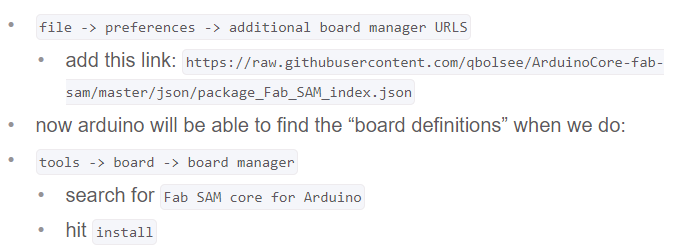
A great guide on SAMDs, bootloading, and setting up the Arduino IDE can be found in Jake's SAMD guide. Taken from there is the following guide to setting up the Arduino IDE to be able to use SAMD boards:
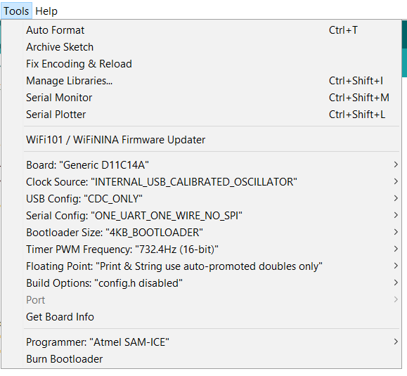
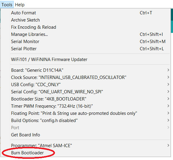
We can now simply select the generic SAMD11 from the boards in the Tools section of the Arduino IDE. Settings should be configured as shown below, if not already showing up like this by default. Sidenote: Not relevant here, but if using hardware serial on a board via UART2 on the SAMD11, will want to choose the "TWO_UART" option in the serial configuration panel.
Bootloading the SAMD MCU Using my Programmer
As mentioned above, the SWD pin header on the left-hand side of my programmer board can now be used to bootload other SAMD boards. The cable connection is shown with an exemplary board on the left-hand side below. In order to flash the bootloader onto the target board, one can simply select "Burn bootloader" in the very bottom of Arduino IDE Tools panel.
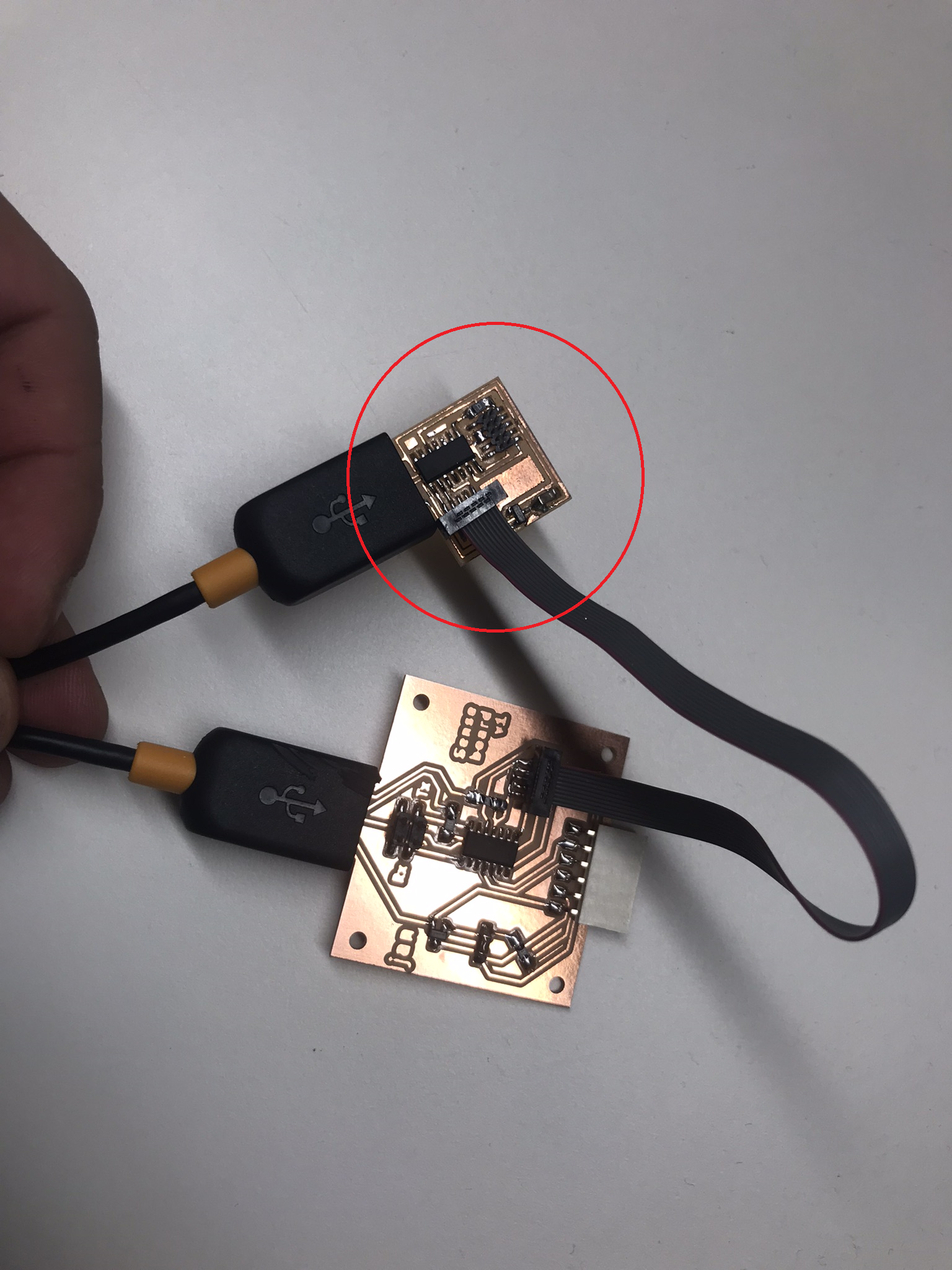
I did this for the board made in week 4 which is now recognized when plugged into my computer via USB. Code can now be embedded on the microcontroller directly from the Arduino IDE via the Upload function.
Embedded Programming
Blink
	        #define LED 5

	        void setup() {
	           pinMode(LED,OUTPUT);
	           Serial.begin(9600);
	           }

	        void loop() {
	           digitalWrite(LED,HIGH);
	           Serial.println(LED);
	           delay(500);
	           digitalWrite(LED,LOW);
	           Serial.println(LED);
	           delay(500);
	           }
Pulse
					#define LED 5
					#define BUTTON 14

					void setup() {
						 pinMode(LED,OUTPUT);
						 pinMode(BUTTON,INPUT);
						 Serial.begin(9600);
					}

					void loop() {
						 int i = 0;
						 for (i=0;i=200;i++){
							analogWrite(LED,i);
							delay(100);
							Serial.println(i)
						 }
					}
Button Push
		      #define LED 5
		      #define BUTTON 14

		      void setup() {
		         pinMode(LED,OUTPUT);
		         pinMode(BUTTON,INPUT);
		         Serial.begin(9600);
		      }

		      void loop() {
		         if (digitalRead(BUTTON)==LOW){
		          digitalWrite(LED,HIGH);
		         }else{
		          digitalWrite(LED,LOW);
		         }
		         //Serial.println(LED);
		      }
This function looks as shown in below video once loaded onto the board.