For an intro to my final project concept, check out this page.
Update 1: 10/12
To stay within my budget, I think the largest mirror I'll be able to afford is 6", as the cost for a good-quality mirror and secondary would probably be $150-$200. I decided to go for a f/5 focal ratio, as the resulting tube length will be about 30". This seems like a reasonable size that will keep the total weight under 30 pounds, which is important because I'll be lugging this thing all across campus. It also ends up being a size that will easily fit in a car, so I'll be able to take this out to a dark sky area and do some proper observing. When I started looking for 6" f/5 mirrors, however, I found that new mirrors are out of stock everywhere due to supply chain issues, and new shipments are delayed until 2022. I was seriously panicking at this point, and even considered changing my final project idea. As a last-ditch effort, I decided to post in the classifieds section of Cloudy Nights, the largest amateur astronomy forum on the internet. To my surprise, I recieved a message from someone who had exactly what I was looking for: a 6" f/5 mirror scavenged from an old Orion Starblast telescope. After verifying that it was in good condition, we agreed to a price of $180 and it will be shipped to me by the weekend. Lesson of the day: you don't have to buy everything brand new.
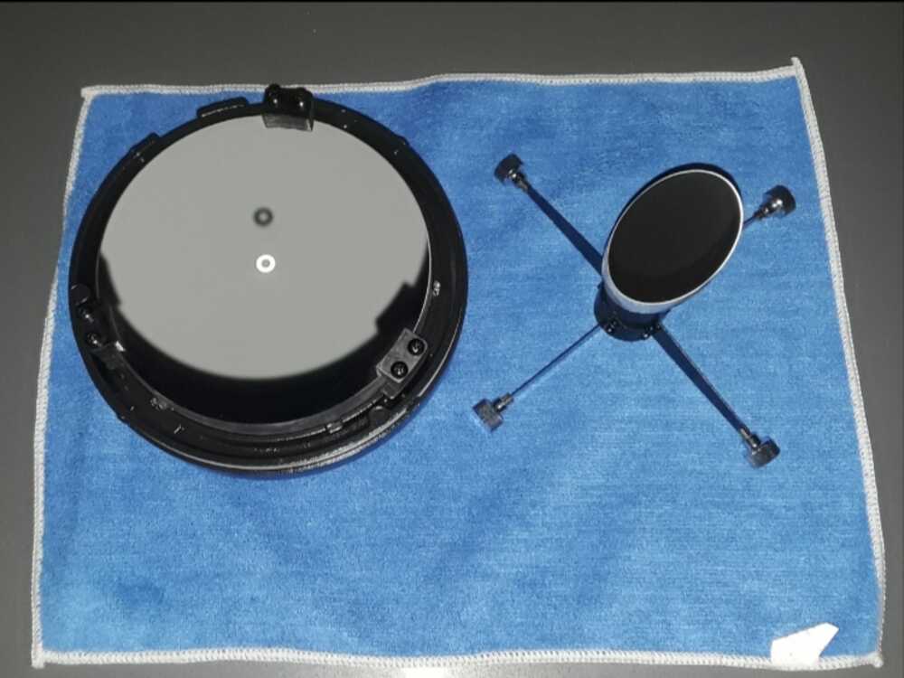
As you can see from the image that the seller provided me, the optics are in near perfect condition. They also come with a mirror cell for the primary and a spider for the secondary. I plan to design and fabricate these components myself, but it is nice to have a backup. Now that the specs of my optics are finalized, I can refine my chassis design.
Update 2: 10/15
I've been looking into methods for tracking the position of my telescope, and it seems that I have two options. One option is to use an inertial motion unit (IMU), which combines accelerometers, gyroscopes and magnetometers to determine orientation. The other option is to use a pair of rotary encoders, which directly track the rotation of the two axes.
I was looking into the BNO055 sensor, which seems to be a popular IMU since it automatically does sensor fusion (combining inputs from the different sensors and giving pitch/roll/yaw output). However, based on what other people have achieved with this sensor, the max resolution is around 1 degree. This is definitely not good enough for the arcsecond resolution I hope to achieve.
This means I'll be going for an encoder-based tracking system, and I have my eyes set on this one. It is an absolute magnetic encoder with 14 bit resolution (16k counts per revolution), which will give me the accuracy I need.
Final Update
So all of this documentation is being rewritten at 11 am on December 13th. Why? Well, a couple weeks ago there was a mixup that caused the entire EECS section repository to be deleted, and it had to be restored to an older version. Since then, I've just been making changes locally on this computer. At 10:45, I wrapped up my documentation and set out to do what I always do: git pull, then git add ., then git commit, and finally git push. Except, after doing git pull, this happened.
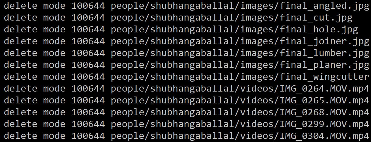
Literally every change I made has been deleted, so I'm having to remake all of it right now. Lesson of the day: if something weird happens to the repository ask someone how to proceed before you do anything. (Also don't leave all your work to a commit on the last day)
Making the Tube
I decided to construct an octagonal tube for the body of my telescope. To determine the sizing, I used this program, which allows me to input the known parameters of my setup (like the focal ratio and diameter of the mirror) to determine the sizing of my tube. After figuring out that each piece needs to be 30" long, 3.5" wide and 0.5" thick, I headed over to the woodshop in N51 to start working on the tube. After talking to Chris, who runs the shop, I selected a plank of ash, as it is the cheapest hardwood.
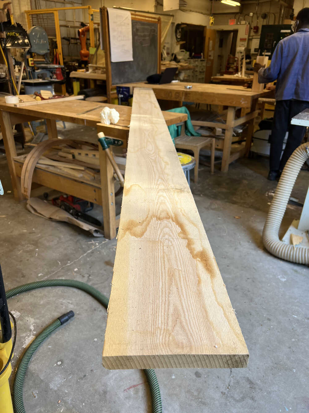
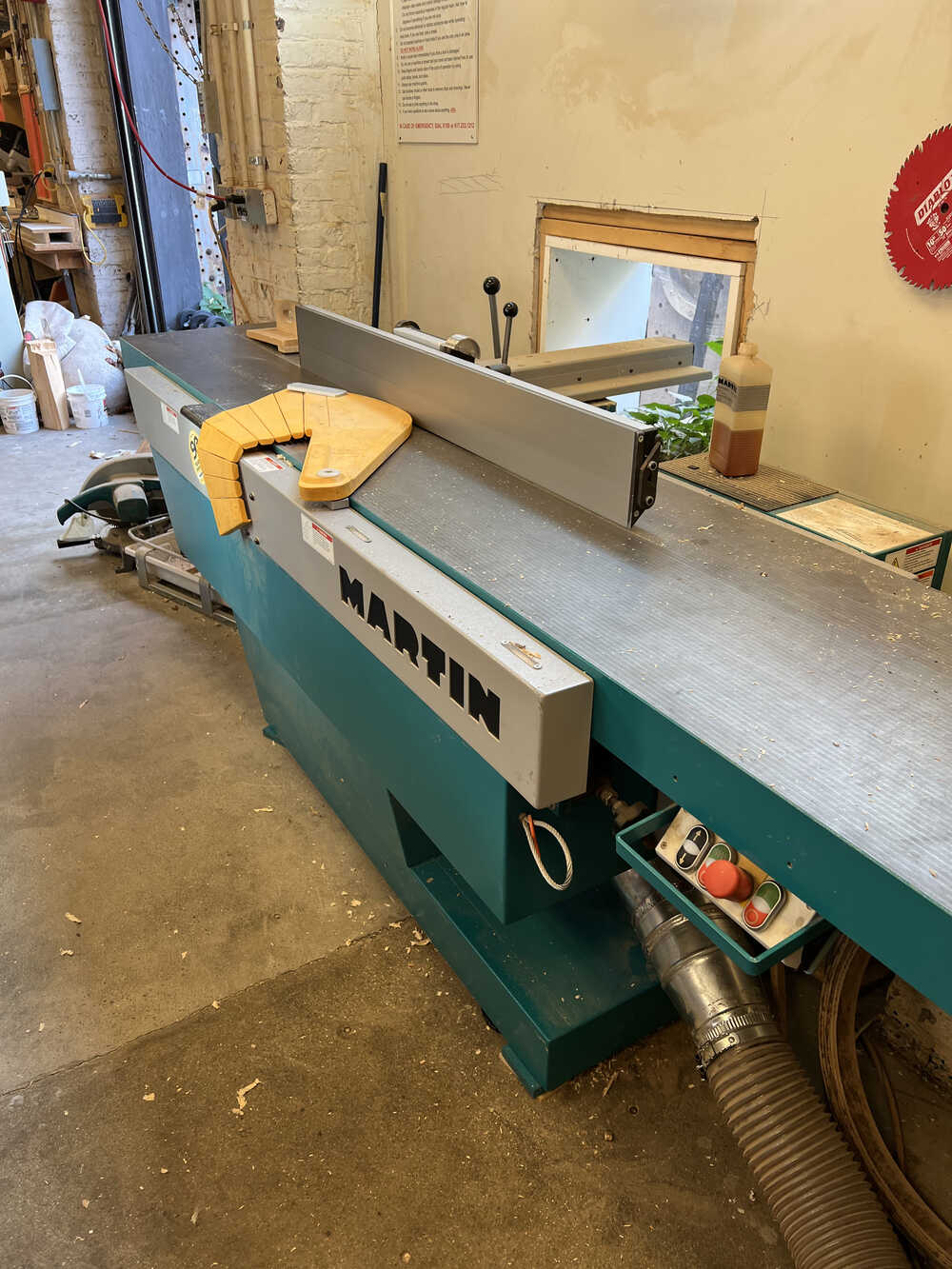
I then chopped the 12'x9"x1" plank into four pieces, each thirty inches long on the miter saw. Next, I made one of the large faces and one of the sides of each piece flat and perpendicular to each other by using the joiner.
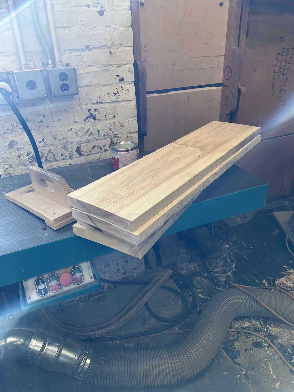
I then used the planer to incrementally take 0.1" off each piece until they were all 0.5" thick.
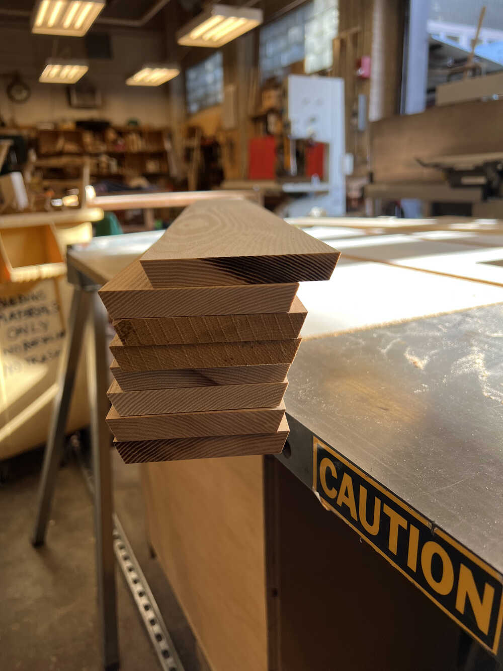
Finally the pieces are off to the table saw to cut them to width, and to cut the 22.5 degree angle into the sides. Since the table saw requires more training to use, Chris did this step for me.
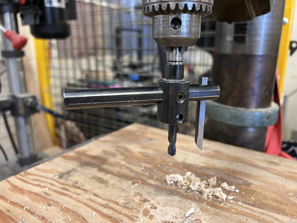
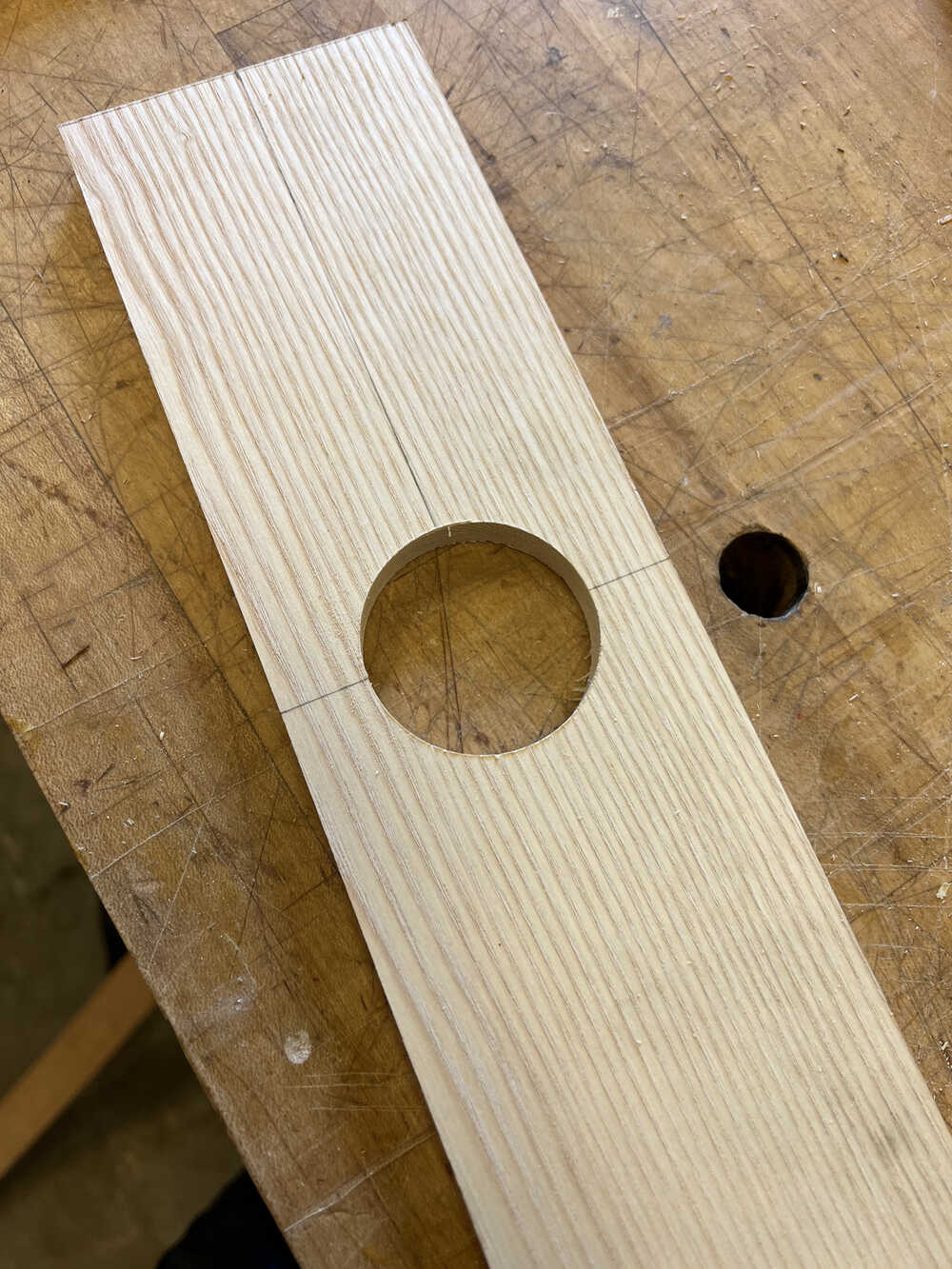
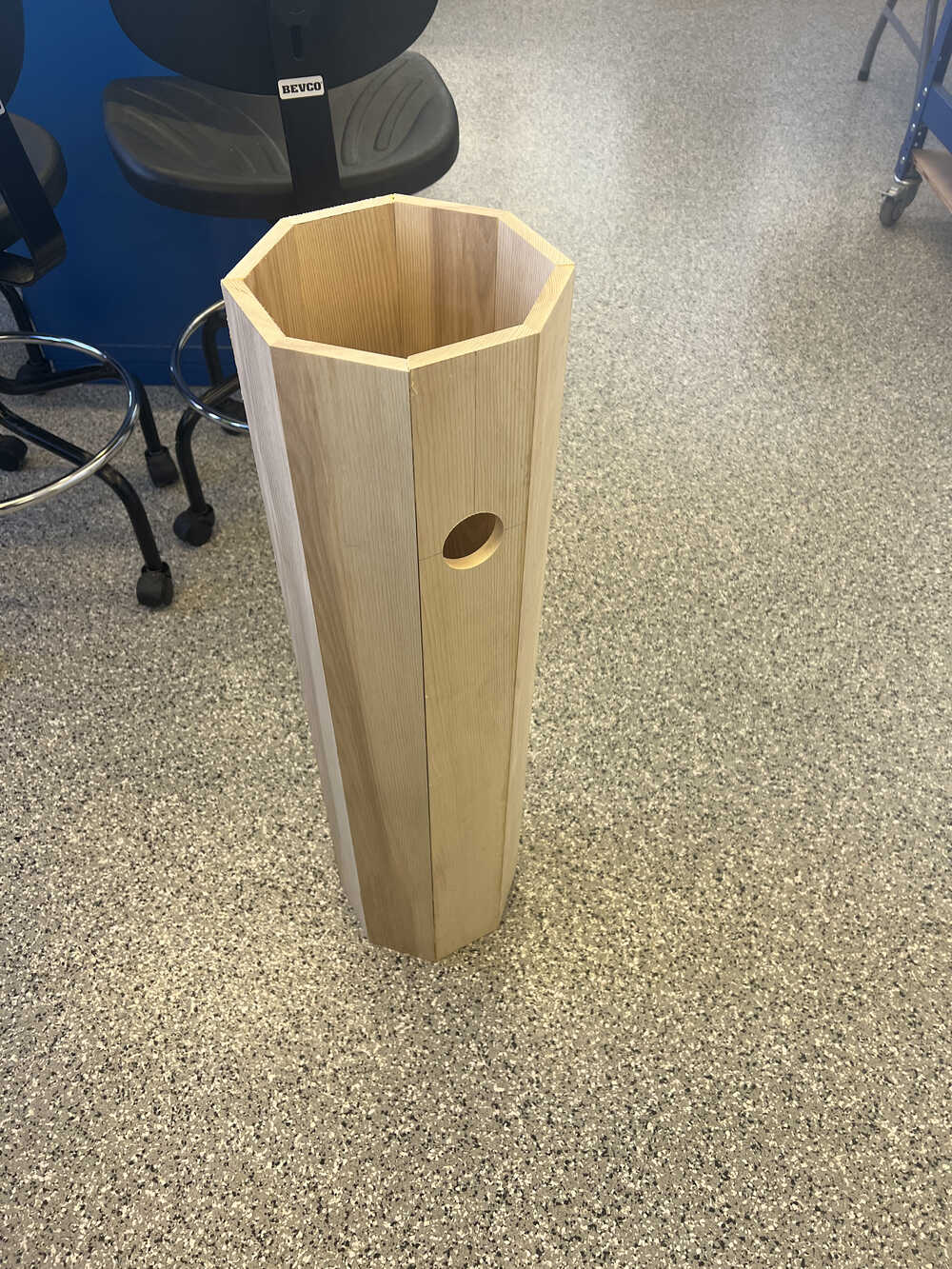
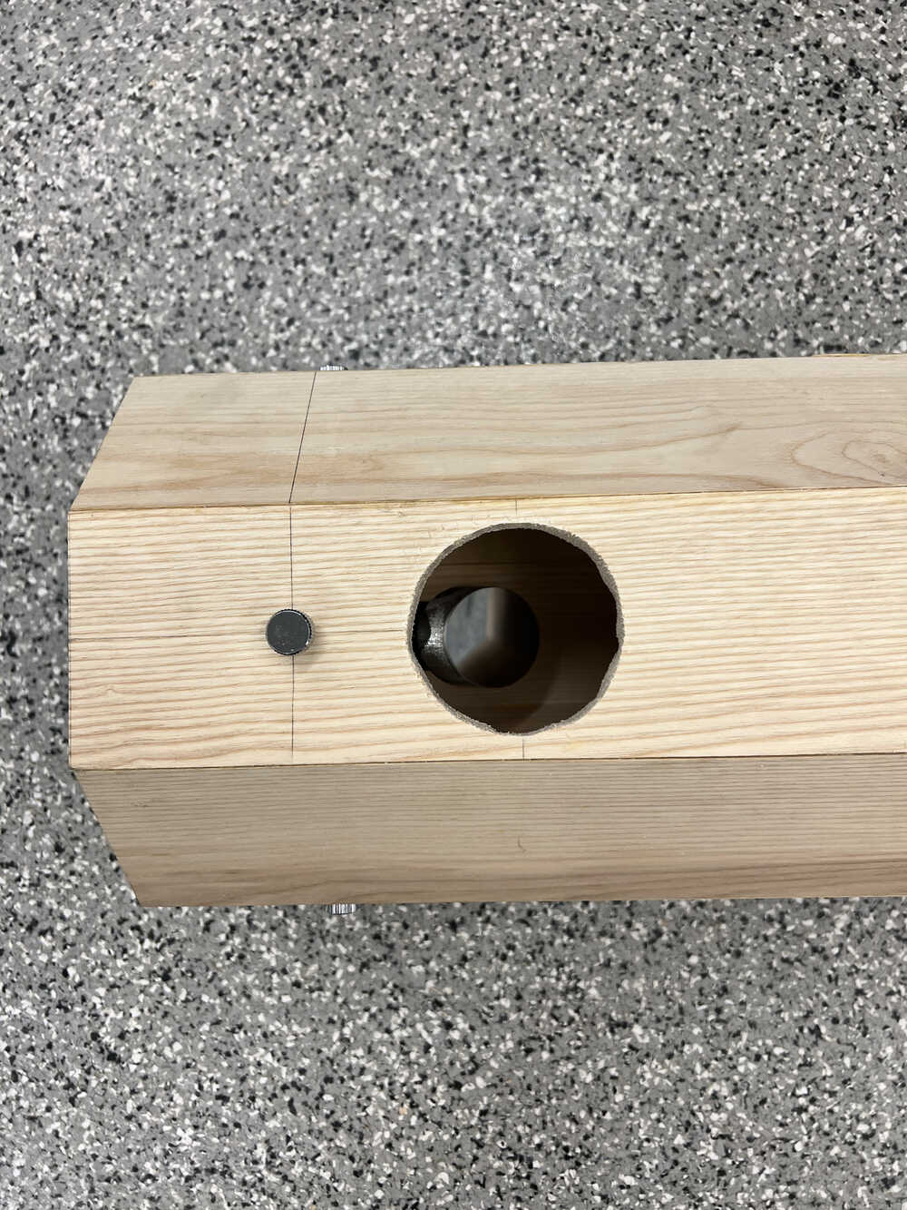
One of the pieces on the tube requires a hole to be cut into it 6" from the end to accomodate the focuser, so I used a wing cutter to carve out a hole of the proper diameter
My next task was to glue all of these pieces together into an octagonal tube. I had initially planned to glue them all together at once, but I quickly realized that I needed to glue them in pairs first. I created a simple laser-cut jig to hold the pieces in the correct orientation while the wood glue dries.
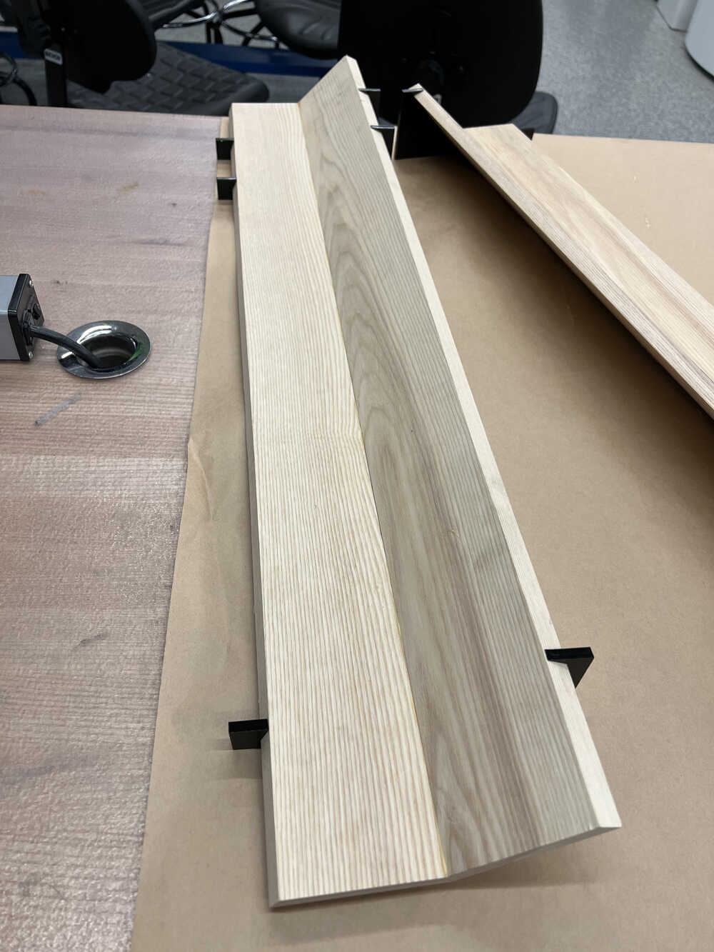
Now, I could use ratchet strap clamps to hold the pieces together to create the finished tube.
Building the Rest of the Telescope
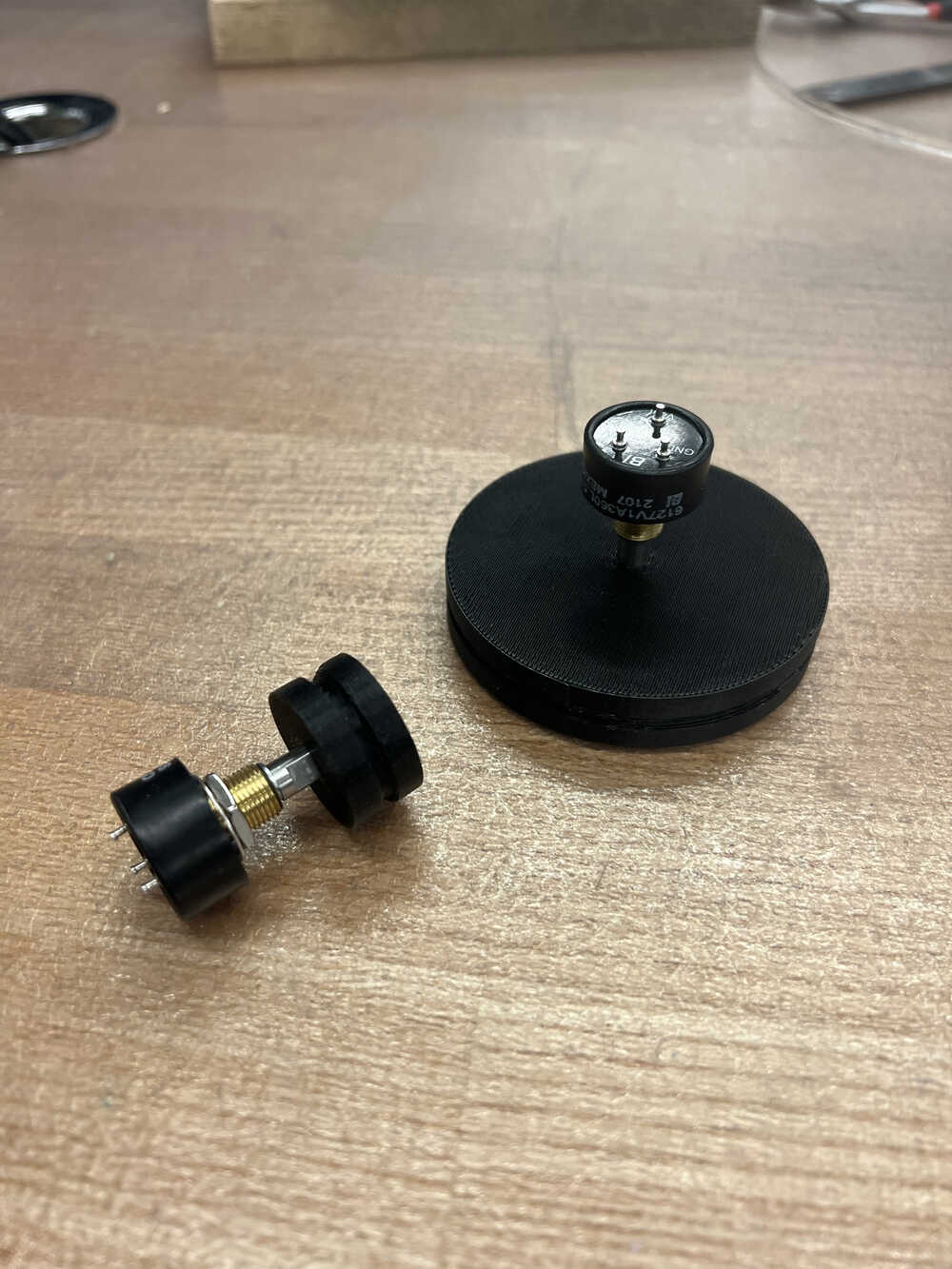
With the tube built, I finalized the design of my telescope. It uses encoders mounted on pulleys connectedby belts to the rotational axes of the telescope.
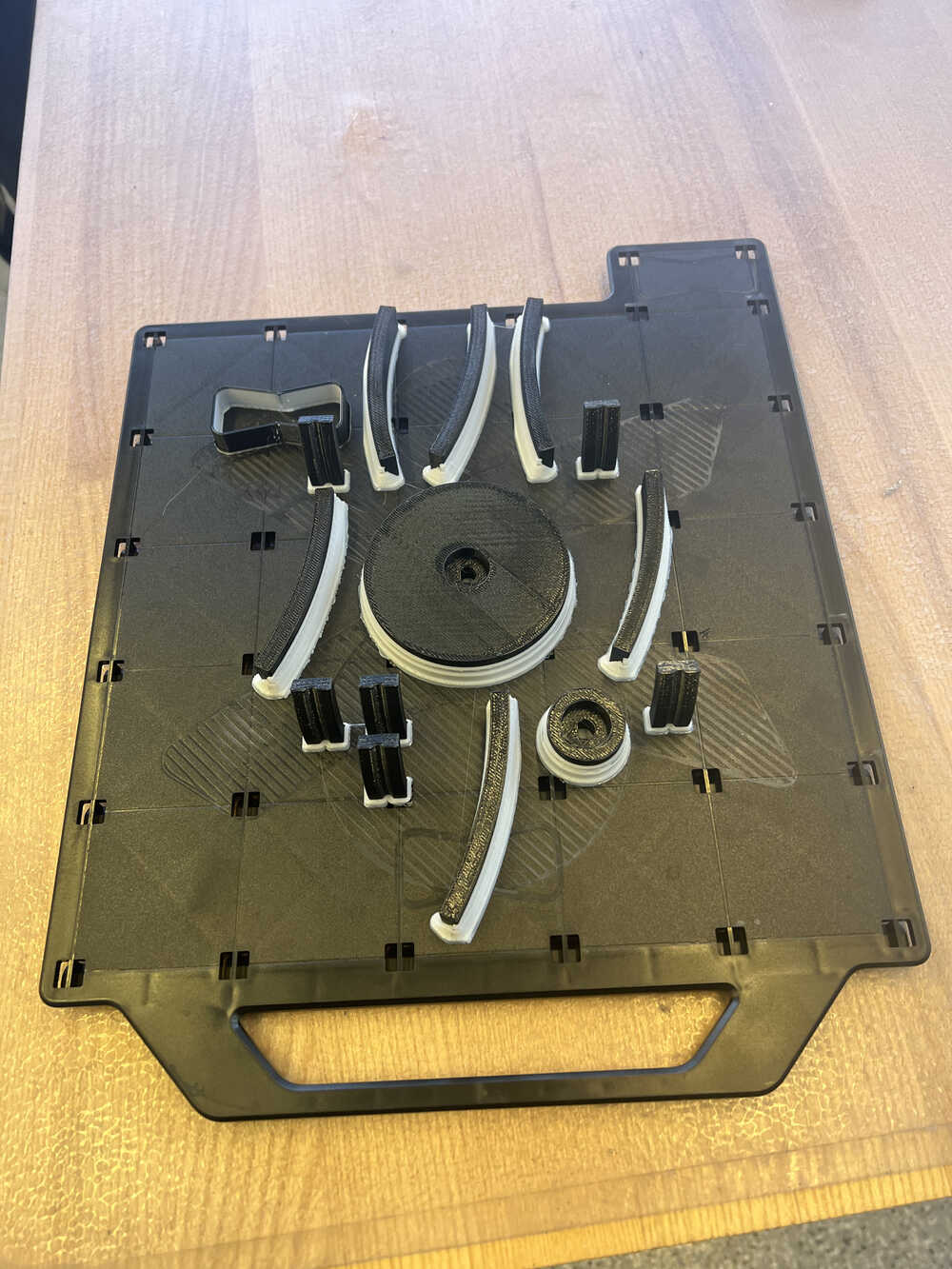
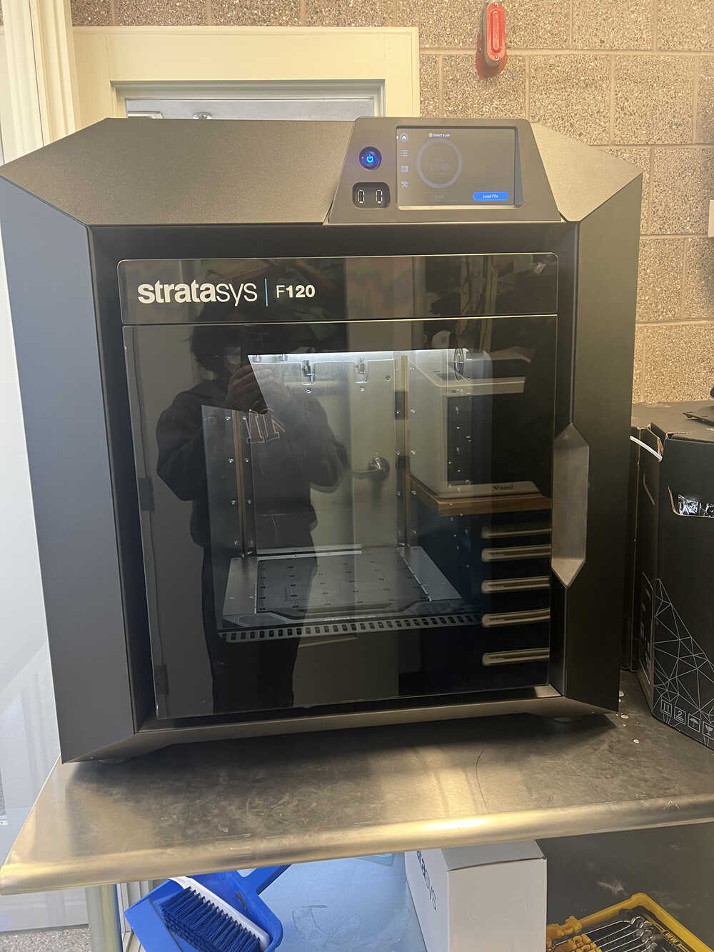
I decided to use the Stratasys F123 printer to make my pulleys. This printer uses dissolvable supports, which need to be removed in an acid bath after printing. While this process does take a while, it definitely improves the part.
Two of the pulleys are attached to the encoders, and these were a perfect fit!
My next task was to modify the mount for the secondary mirror, known as the spider, to fit my tube. The spider my mirror came with had vanes that weren't quite big enough for me, so I created my own by 3D printing longer vanes on the Sindoh and gluing M5 screws to the ends.
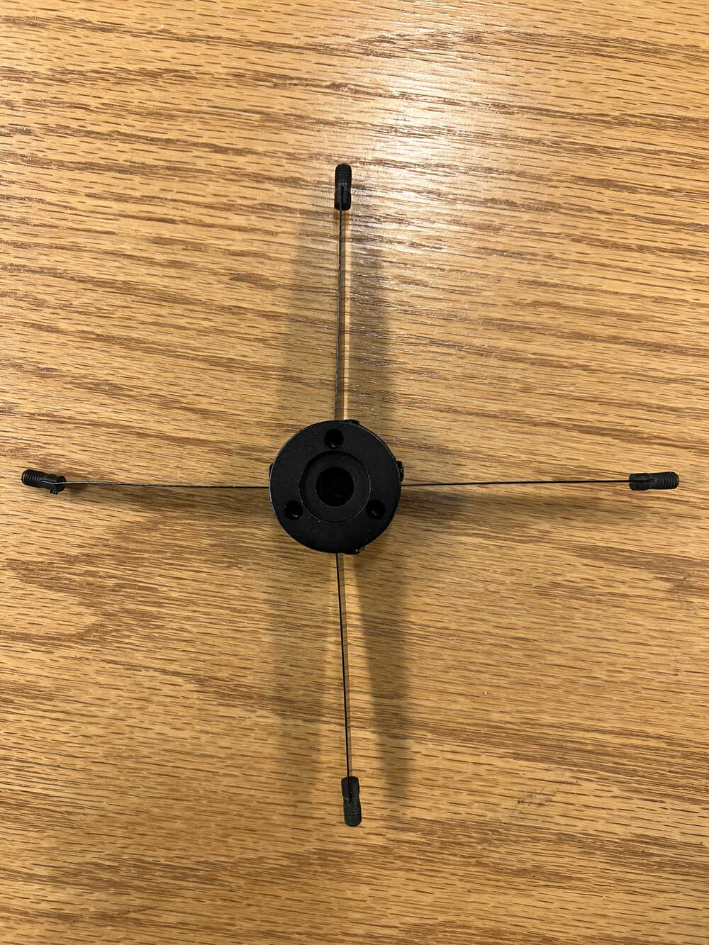
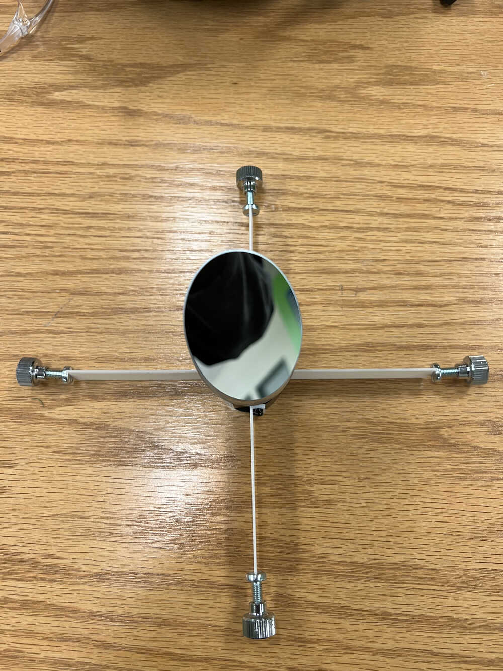
I simply switched out the vanes and used the rest of the existing hardware to mount it in my tube. After drilling four 0.25" holes in my tube, my secondary was in operation!
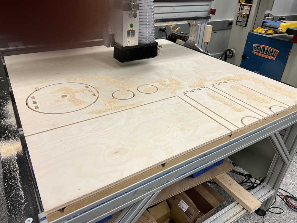
To make the mount, I cut the pieces on our router out of 0.5" plywood.
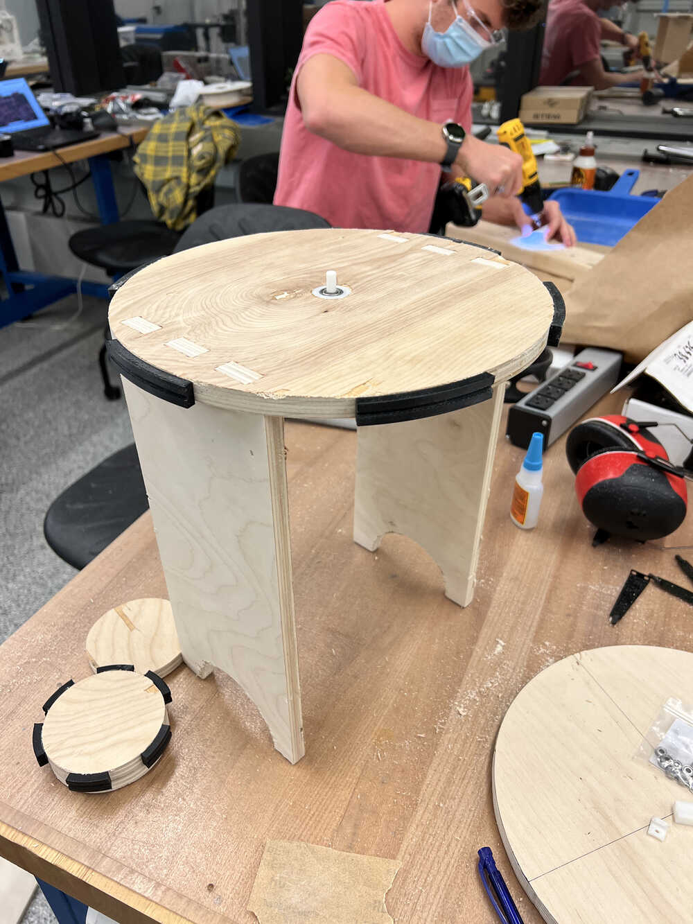
Assembly was straightforward, as the wooden pieces were press fit together, and plastic pieces were super-glued onto the wood. To decrease friction on surfaces that slide against each other, I used adhesive-backed sheets of UHMWPE ordered from McMaster.
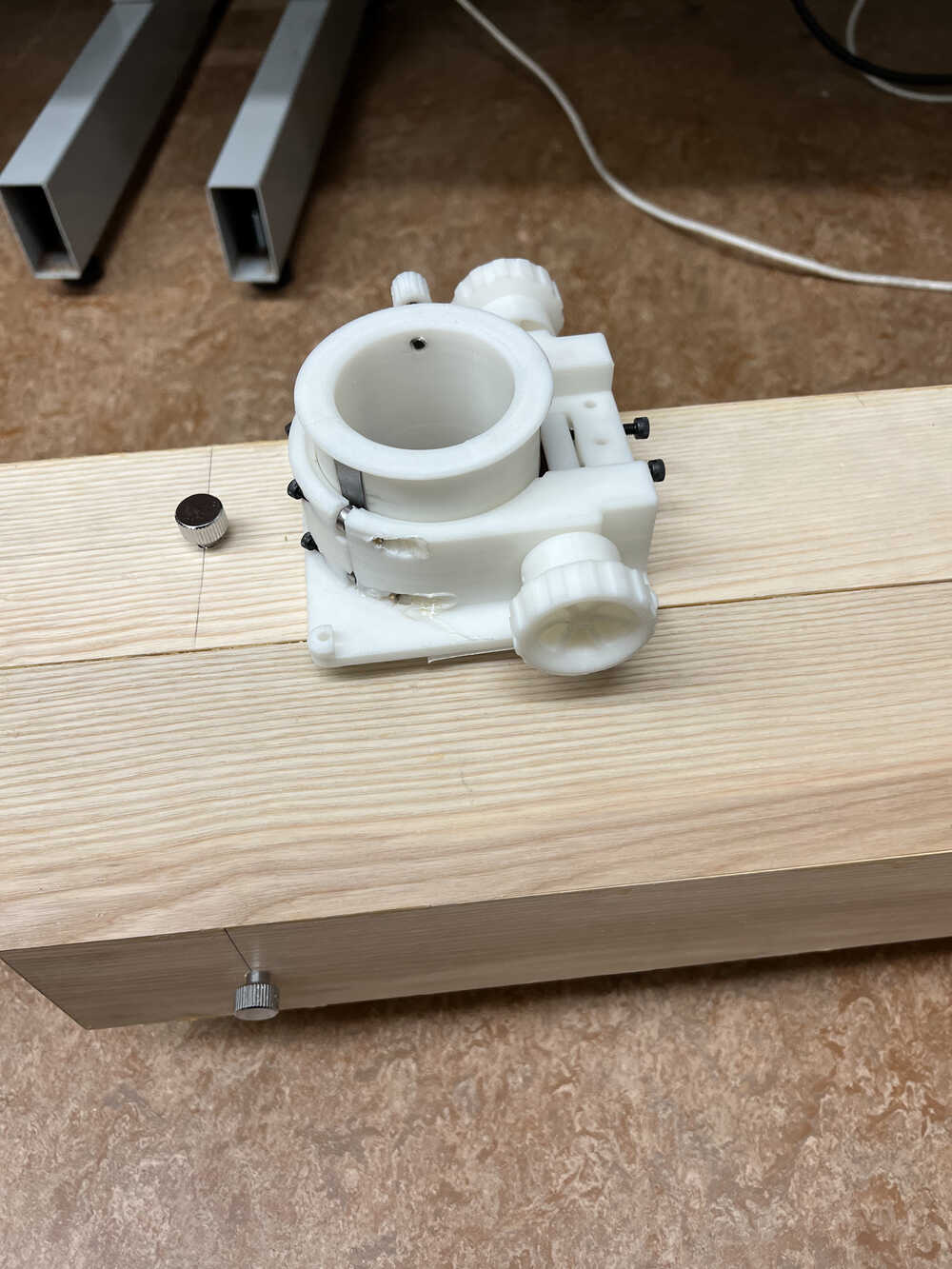
Next, I fabricated the focuser, which I designed/modified to fit my telescope based on the design of Marco Miglioni. The assembly involves heat set inserts, which can be pushed into FDM printed parts using a soldering iron. These are a reliable way of adding screw threads to 3d printed parts, but due to my inexperience with using them, it got a little bit messy.
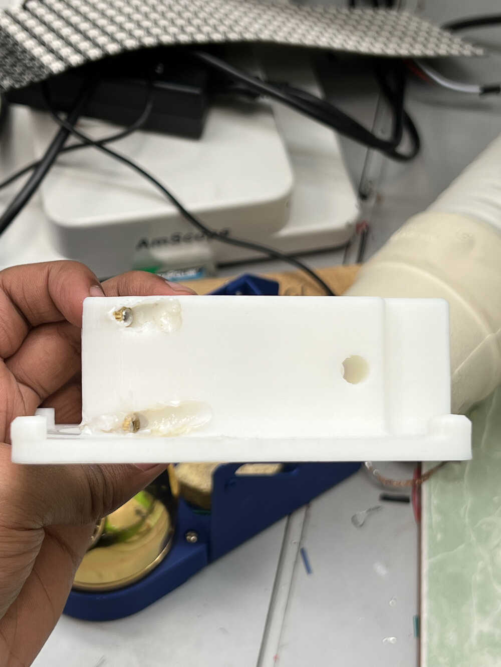
As I was putting the focuser together, I realized that some of the 3D printed parts were slightly dimensionally inaccurate. This led to the pinion not making good contact with the drawtube, preventing me from raising and lowering the focuser with the knobs. To fix this, I glued a cut rubber band to the drawtube to press against the pinion and give it something to grip against. This last-minute solution thankfully worked. However, I ran into another issue when trying to attach the focuser to my tube: I had undersized the hole! After twenty minutes of hard labor with a rasp to widen the hole, I was finally able to fix the focuser. Although I had initally planned to permanently attach it with glue, I instead went with double-sided tape as I plan to remake this part in the future.
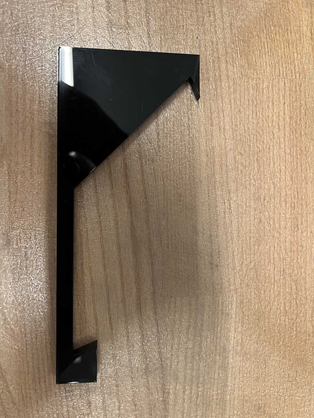
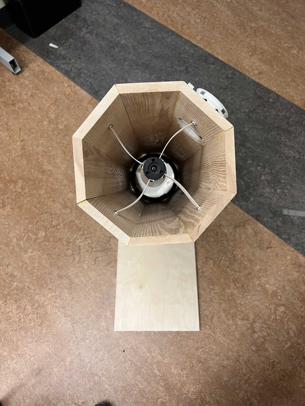
I then mounted the primary mirror into the back of the tube with a piece of acrylic and two scrap pieces of plywood. This was an incredibly difficult process, as my tube did not end up being a perfect octagon, as a result, it was essentially impossible to center the mirror exactly. Additionally, the weight of the mirror made it keep falling over when I tried to glue it, making the entire process extremely frustrating and take far too long. After gluing on the altitude bearings, my tube is finally finished!
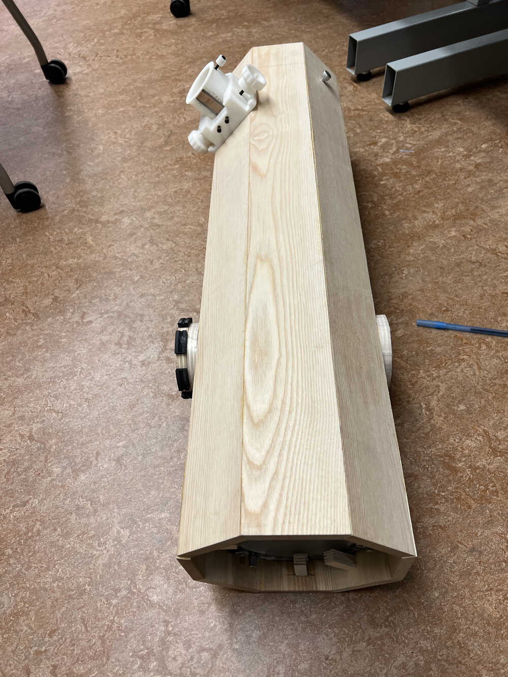
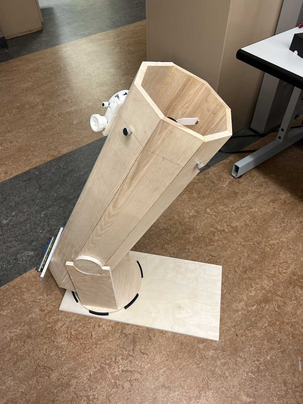
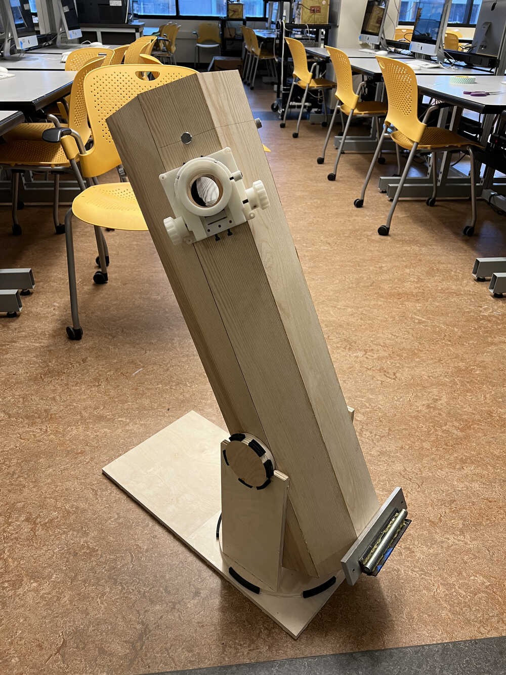
I set the tube on the mount, and voila, my telescope (mechanically) is complete!
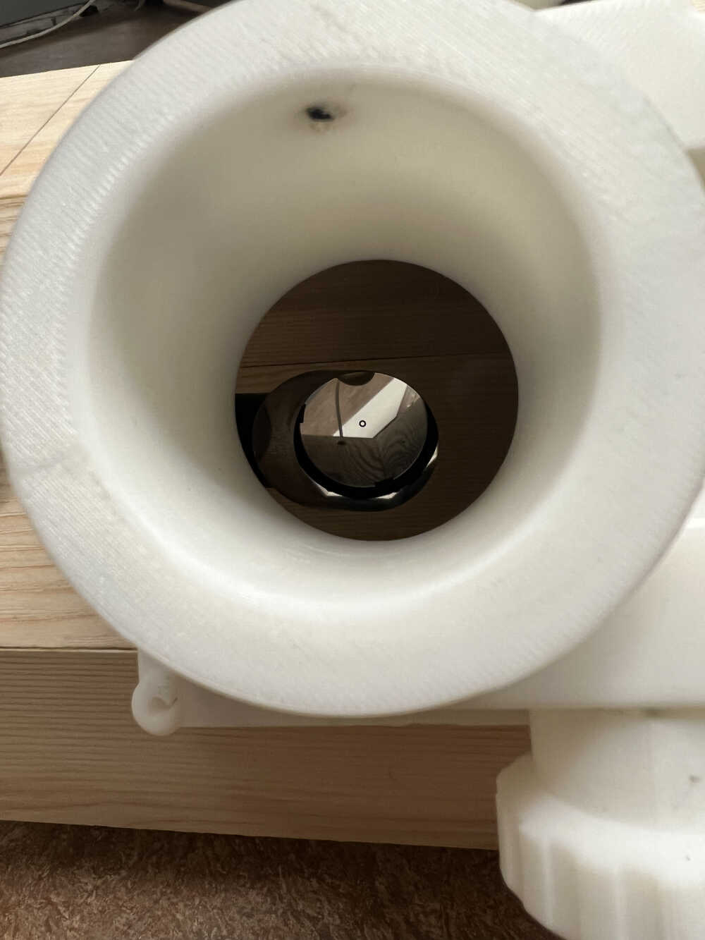
The final step in getting the telescope to operate is collimation, where the mirrors are aligned properly with each other to produce a clear image. In order to do this, there are adjustable screws on both the primary mirror cell and the secondary mirror spider to tilt the reflective surfaces. However, despite consulting multiple guides and trying for several hours, I just could not get a proper image to form. I tried my telescope eyepiece as well as Anthony's microscope camera, but nothing seemed to work. I suspect this likely has to do with my difficulty in accurately mounting the primary mirror. If the two mirrors are too far off-axis, it can't be corrected for.
Takeaways and Conclusion
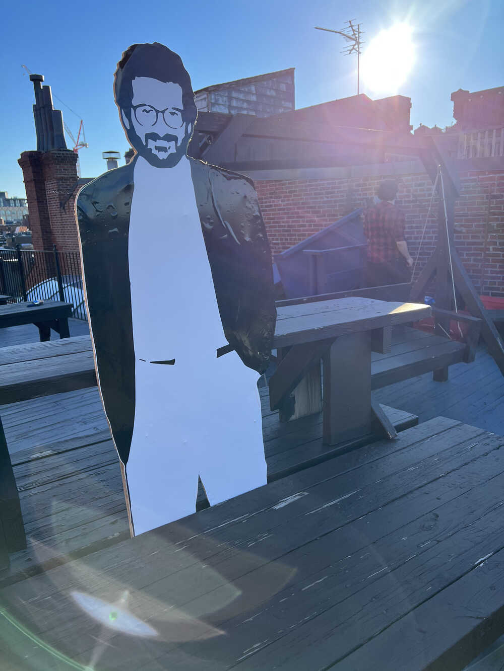
Because of my difficulties getting the physical construction of the scope right, and due to the time spent unsuccessfuly trying to calibrate the optics, I wasn't able to integrate my electronics (encoders, displays and microprocessor) with the telescope even though I had them working seperately. The encoders would measure the position of the axes, and prompt the user to turn the scope up/down and left/right using arrows displayed on the OLEDs to bring the telescope to a particular target. In preparation for the showcase, I had moved my cutout of Professor Gershenfeld to the roof of Nu Delta, the frat across the river where Anthony lived in his undergrad days. I had hoped to use this as a target for the demo.
In retrospect, I probably should have considered a simpler and more accurate method of constructing the tube. While I find woodworking fascinating, I clearly lack the skill needed to get the precision required for constructing a telescope tube. This led to multiple delays/issues in the physical construction that set me back in my timeline, and led to an unfinished final project. I've learned a lot about project management through this experience, and I'll definitely be using the lessons I learned from this to plan out future projects and increase my chances of success.