This week's assignment is to make an in-circuit programmer that includes a microcontroller. This involves selecting a circuit design, optionally modifying it, milling the PCB, soldering components, and testing.
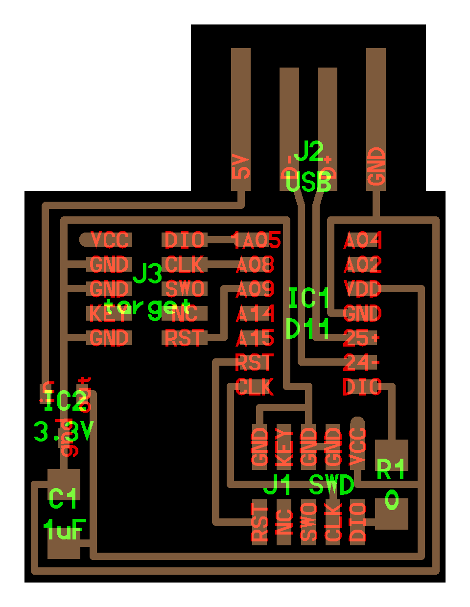
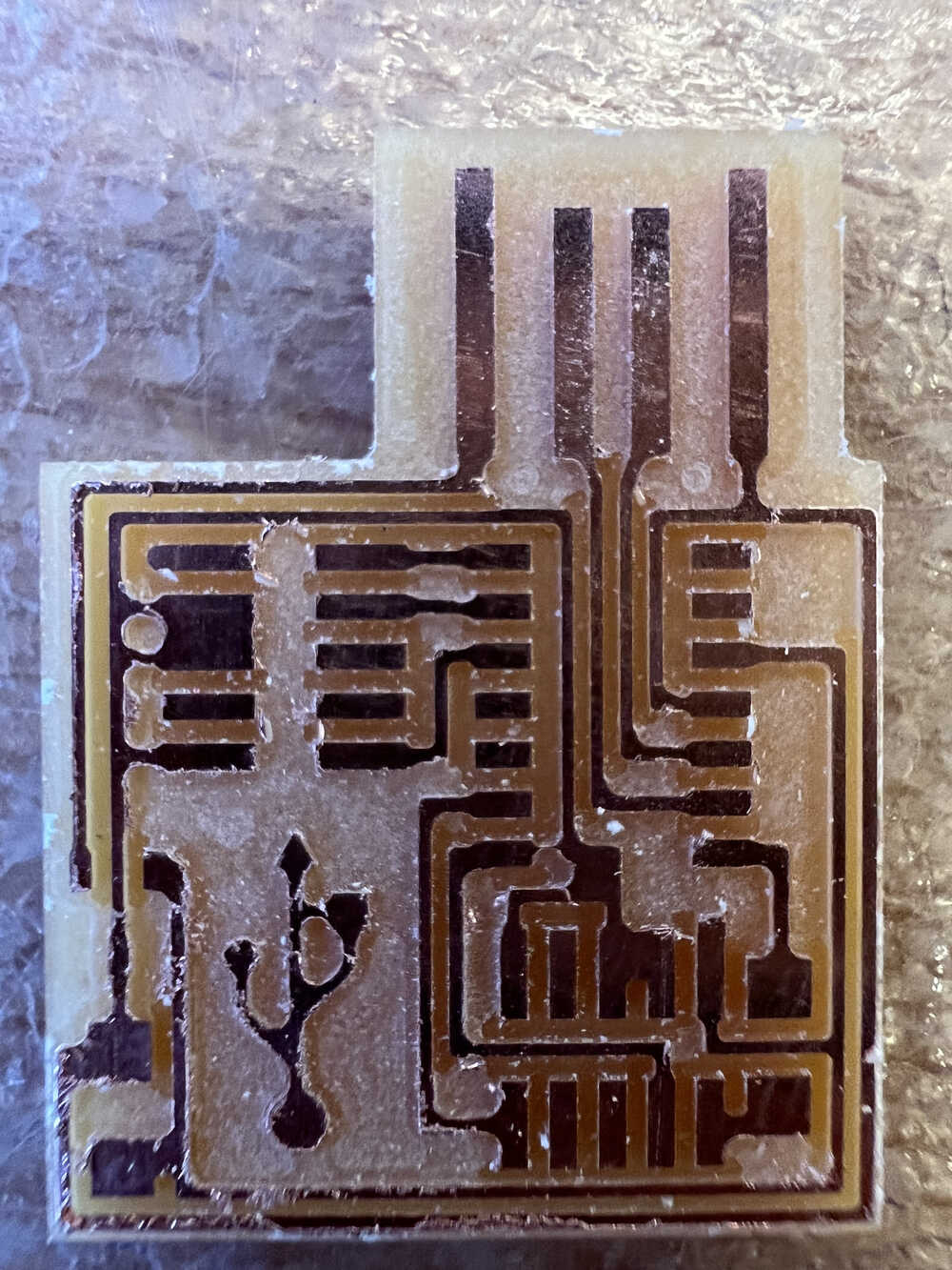
I chose to make the hello.CMSIS-DAP.10.D11C board, which is shown below. I modified the trace design by inserting the USB logo into the empty area on the board.
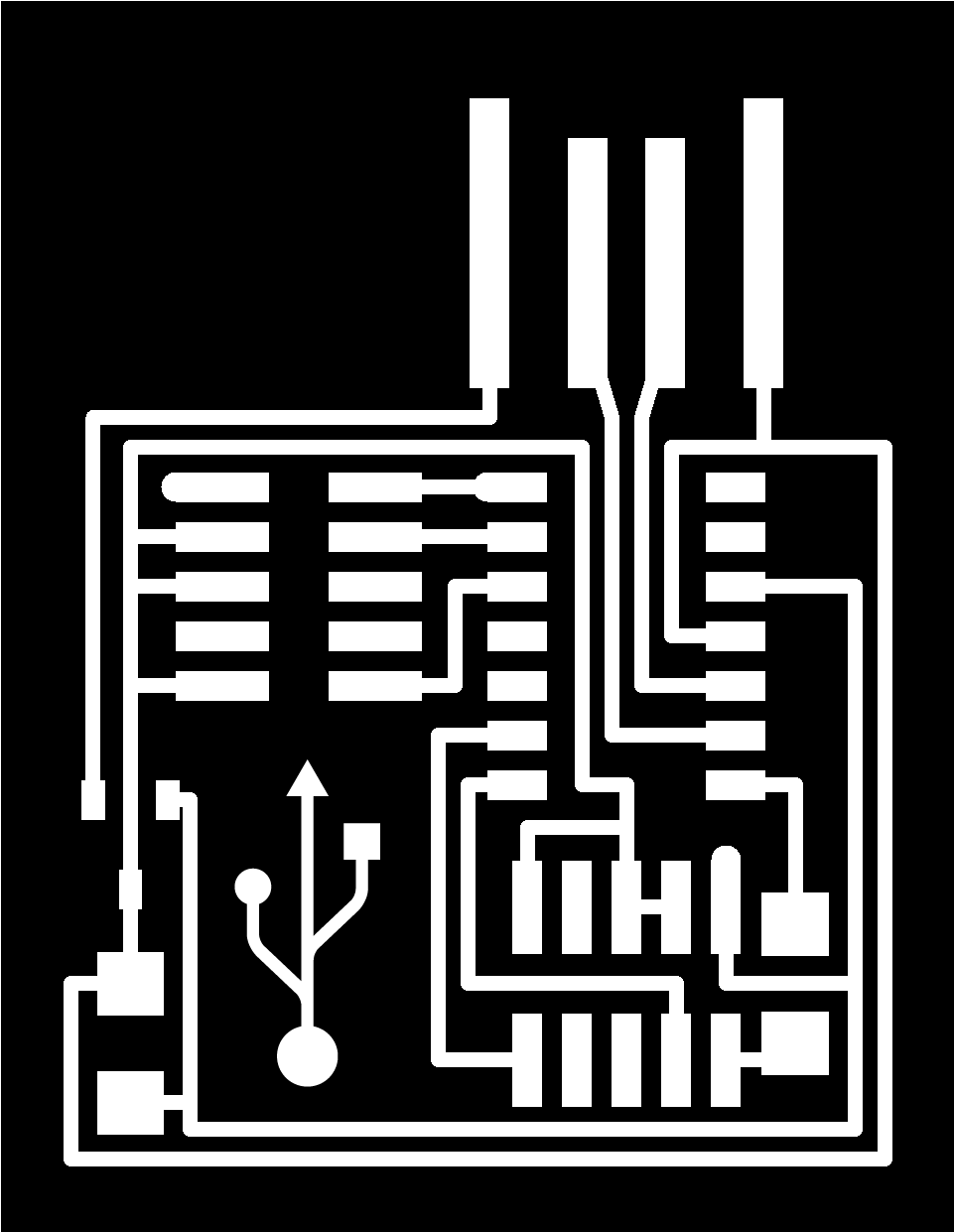
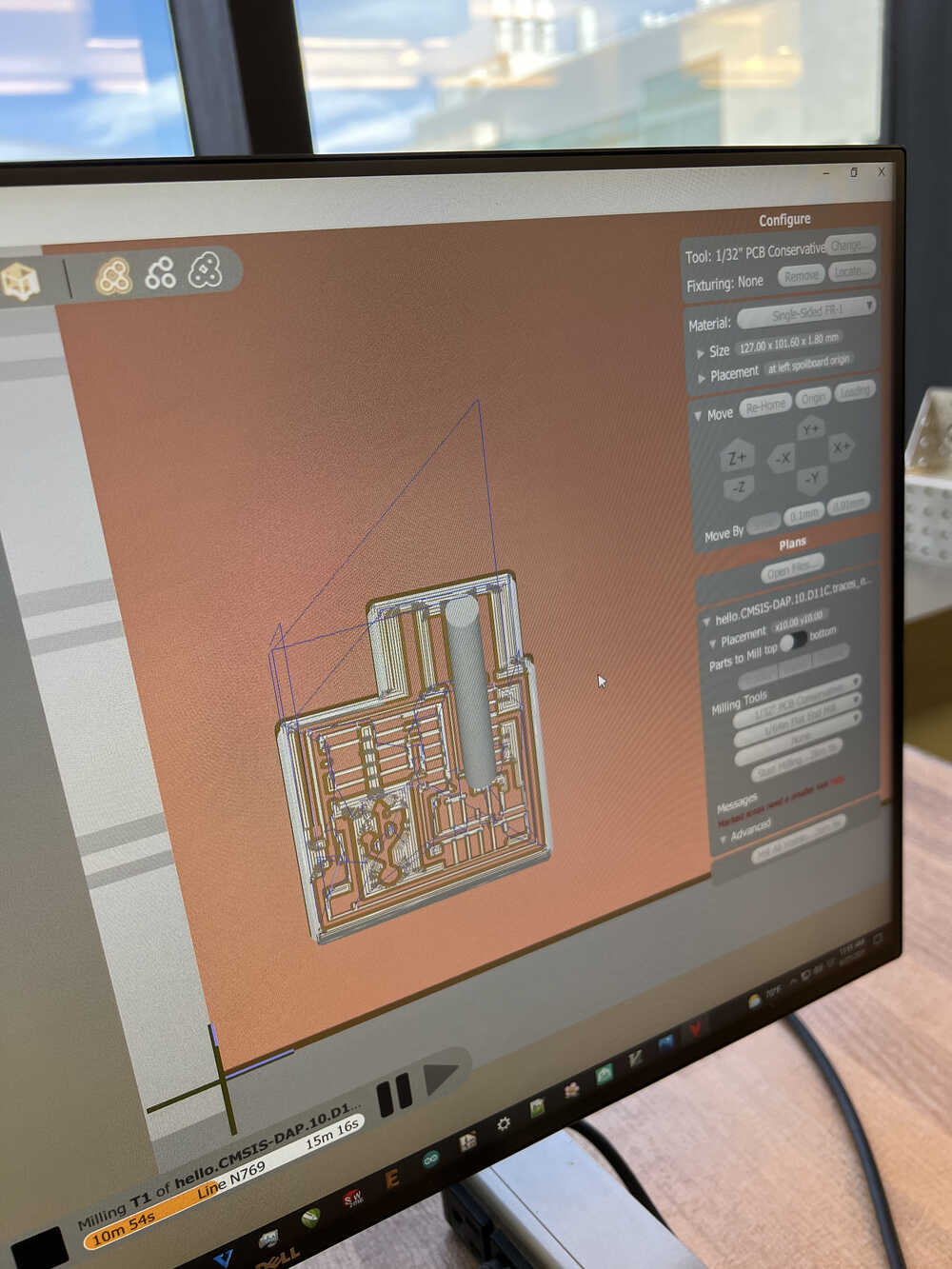
I then used the othermill to mill my PCB. After using mods to convert the trace and outline pngs into a gerber file, I used the othermill's software to machine the board out using 1/32" and 1/64" bits. I accidentally broke the 1/64" bit by crashing it into the aluminum plate while setting up the mill, but other than that, I didn't have any issues. This board took about 30 minutes to mill.
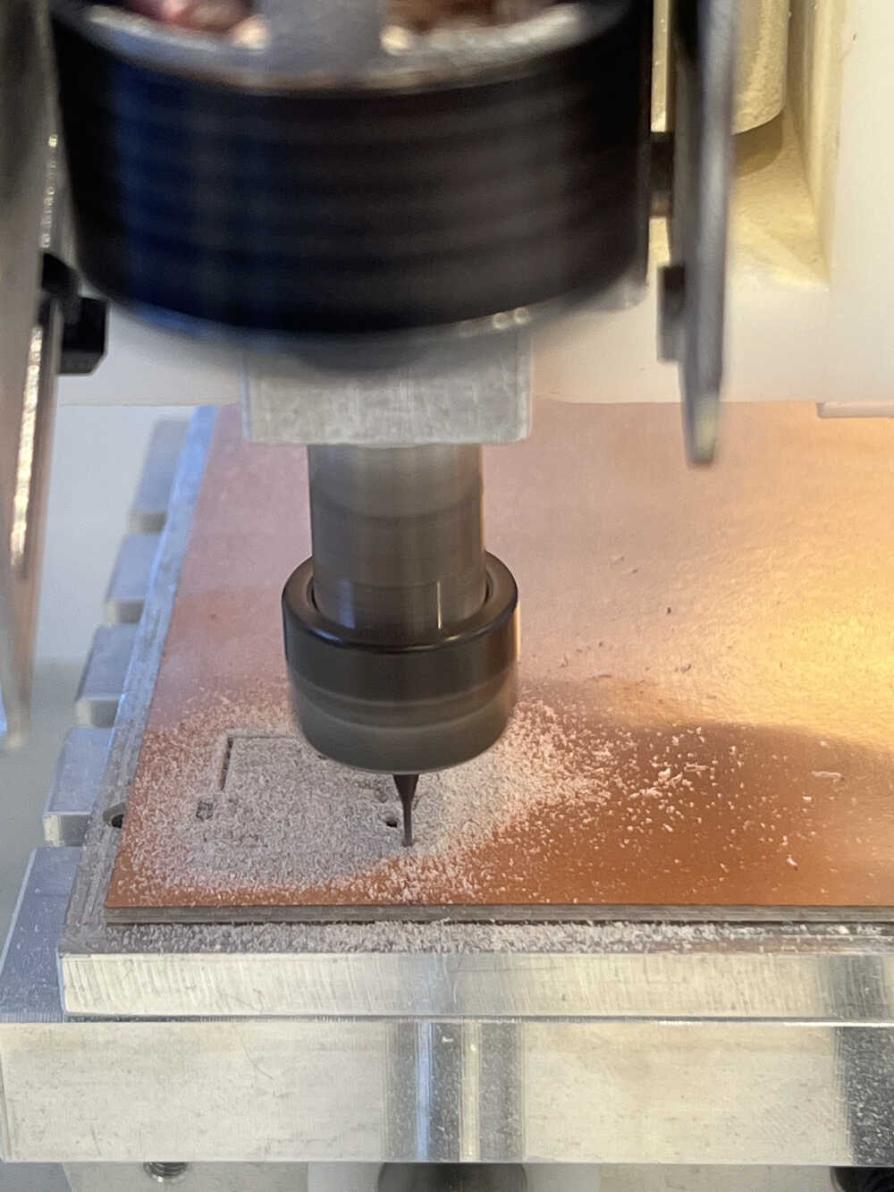
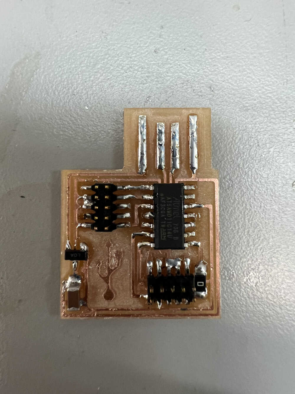
The board came out a little less than perfect, so I had to do some deburring and remove a bridge (I have no idea why this wasn't machined out properly) with an x-acto knife.
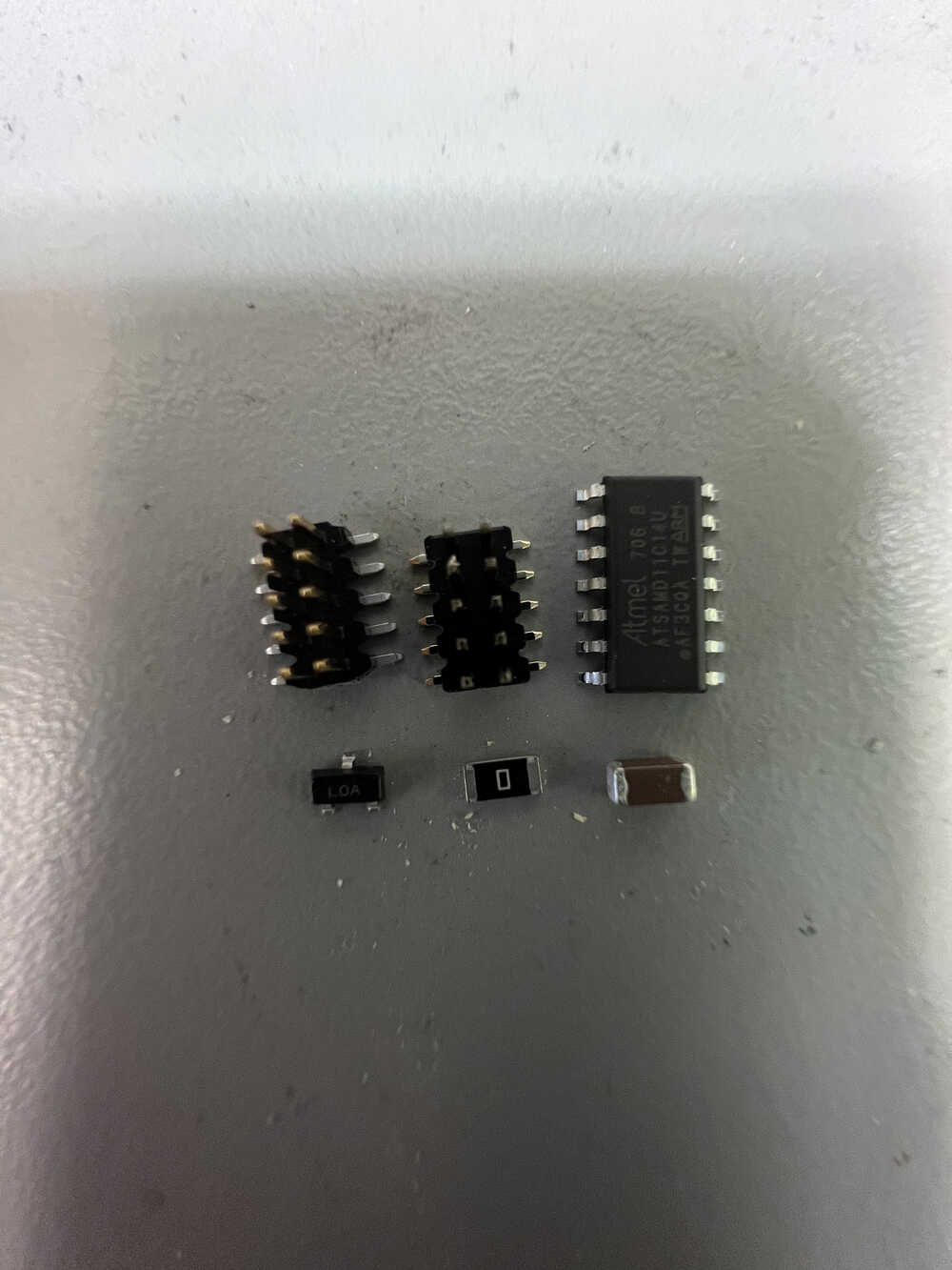
The next step was to solder the components onto the board. The components include a SAMD11C chip, a 1 uF capacitor, a 0 Ω resistor, a 3.3V regulator, and two 2x5 pin headers.
Although I was new to surface mount components, my previous soldering experience came in handy and it didn't take long to finish the board. Finally, I tested the board to verify that it works.