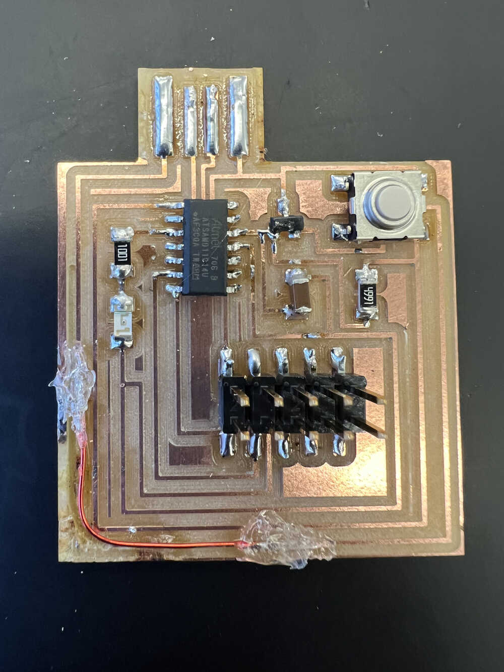
This week, we went back to program the boards we created two weeks ago. Unfortunately, my assignment for this week started off with a bit of drama, as I seem to have misplaced the board that I made. As a result, I had to take a slightly defective spare PCB that I had milled, and resolder all the components onto that. The reason that I hadn't used this board the first time around is that I gave the wrong DPI to mods when cutting the outline, and it milled through one of the traces. Thankfully, this was pretty easy to remedy by replacing the lost trace with a bit of magnet wire, which I soldered on and then hot-glued to keep it secure. The rest of the soldering was especially easy since it was my second time doing it.
I then got Anthony's help to get the bootloader onto the board. We ran into a slight complication because I used the 10-pin header, ignored the location of the six pins not used for programming the board. The fix for this was to use pin "extension cords" to individually connect to the four pins used to burn the bootloader on. After completing this step, I'm ready to load programs onto the board via USB!

I wrote a basic blink program for the board. After consulting the datasheet for the SAMD11C14A processor and my board schematics, I determined that my LED is connected to pin 9 and my button is connected to pin 4. In the setup portion of the code, I assign the LED pin to output and button pin to input. Then, in the loop section of the code, I check if the button is pressed by reading the voltage from that pin. If it is "LOW", meaning the button is pressed, I change the state of the LED.
One issue I had is with the button "bouncing", meaning that one press is registered as multiple presses. As a result, the LED changes state multiple times. I didn't have time to add "debounce" code this week, but I know that it involves setting a time interval (e.g. 125 ms) and ignoring any inputs over that interval after the initial button press.