Embedded Programming
This week's assignment: read the data sheet for your microcontroller and program your board to do something.
[1] Shift Registers & LED Matrix Control
Continuing with the 16x16 LED matrix board I designed during week 4, I planned on getting a basic test program working this week which would allow me to do some simple animation with the LED matrix. I designed the board to use the 74HC595 SIPO shift register in order to control the massive number of LEDs. In the way I wired my board, I can use 3 pins of the ATMega328P to control 16 LED pins using 2 of the shift registers chained together. The way shift registers work is that there are 3 control pins: clock, data, and latch. By continually pulsing the clock pin and setting the data pin to desired 0/1 values, you can store a binary number bit by bit in the storage register of the shift register. In this case, because the 74HC595 is an 8-bit shift register, it can store 8-bit binary numbers in its storage register (1 byte). Then, upon setting the latch pin to high, the value in the storage register is copied to the latch register, which corresponds to the 8 parallel outputs of the shift register. Fortunately, all of this complicated logic to "write" a single byte into a shift register is encapsulated by the Arduino library's shiftOut() function. Because I was using two 8-bit shift registers chained together to act as one 16-bit shift register, I just needed a little bit of bitwise math to create my own version of the shiftOut() function. The way I designed my board uses one set of shift registers to control the rows of the LED matrix and another set to control the columns of the LED matrix. Therefore, I created the following functions to control the shift registers:
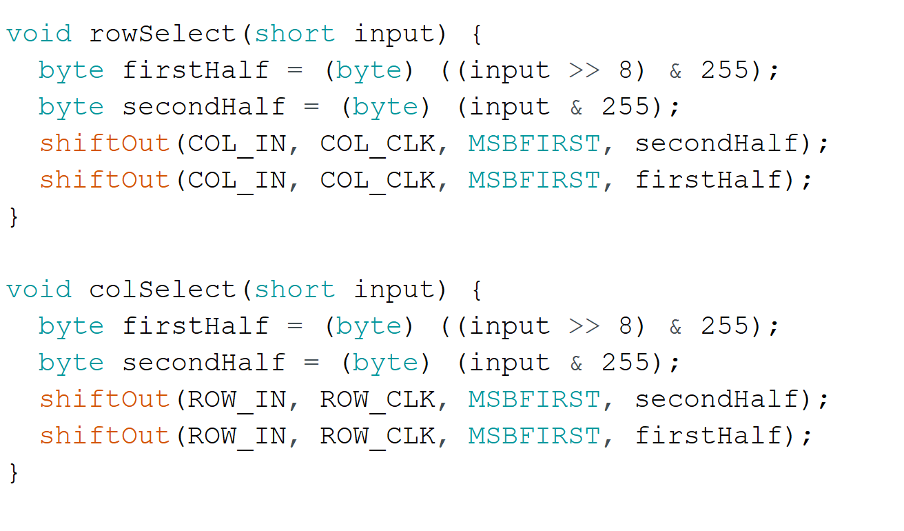
One thing to note is that the Arduino library's implementation of shiftOut() is terribly inefficient, but the speed at which it runs is sufficient for my scenario. In theory, it is possible (and actually not too complicated) to implement efficient shift register control by taking advantage of the ATMega328P's hardware SPI, but I did not feel like spending the time to do this for an unnecessary performance boost.
Back to controlling the LED matrix: the way I've wired the LEDs is that all LEDs in one column share the same anode, while all LEDs in one row share the same cathode. Each column anode is connected to one of the 16 outputs from the two column shift registers, and each row cathode is connected via a MOSFET to ground, the gate of which is connected to one of the 16 outputs from the two row shift registers. Therefore, by selecting one particular row, the column shift registers can be selected to display one row of an image. Then, by cycling through rows really fast, persistence-of-vision makes it look like the entire LED matrix is on.
[2] Displaying Static Images
Using this idea about persistence-of-vision, displaying a static image for a set amount of time is pretty straightforward. Essentially, we just want to light up one row at a time as fast as the processor can handle until we've waited for the specified image display duration. The code to display an alternating grid of off and on LEDs for 500ms looks something like this:
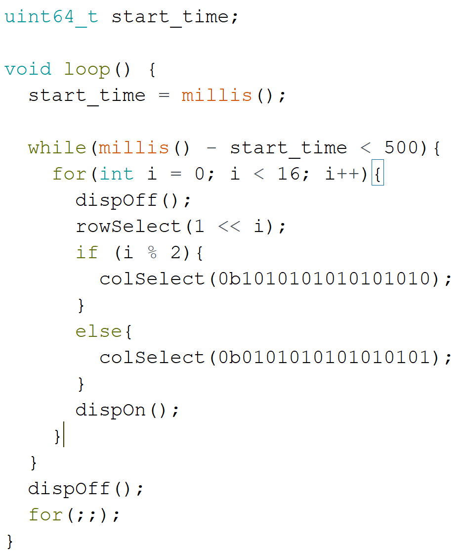
[3] A Simple Animation
Taking the previous idea one step further, I was able to display a simple animation which was just an alternating checkerboard pattern. By copying the code above for one static image and switching the binary 0's and 1's (e.g. in 0b1010...) and then displaying this new image after the previous one for a set image duration in loop(), I ended up with the following animation:
It was a great relief to see that all of the soldering and bodge wires worked! Check out week 8 for even better things with the LED matrix.