
My final project is light on output. My thought ball will send accelerometer data to a browser where some data viz can happen, but there isn’t a lot of actuation.
So I’m going to take it light and try to wrap up some loose ends from the last two weeks, plus tackle some related board-building that I’ll need for my thought ball. By “take it light” I mean I‘m not going to leave 3.3-5V land, which is where the more serious motors live.
So here’s my plan:
For the first time in a month I‘m free during the weekend so I might actually be able to pull it off.
First order of business was to redesign my breakout board. Here’s my diagram, which has serial inputs, UPDI, eight exposed pins, and four exposed bins for both ground and VCC.
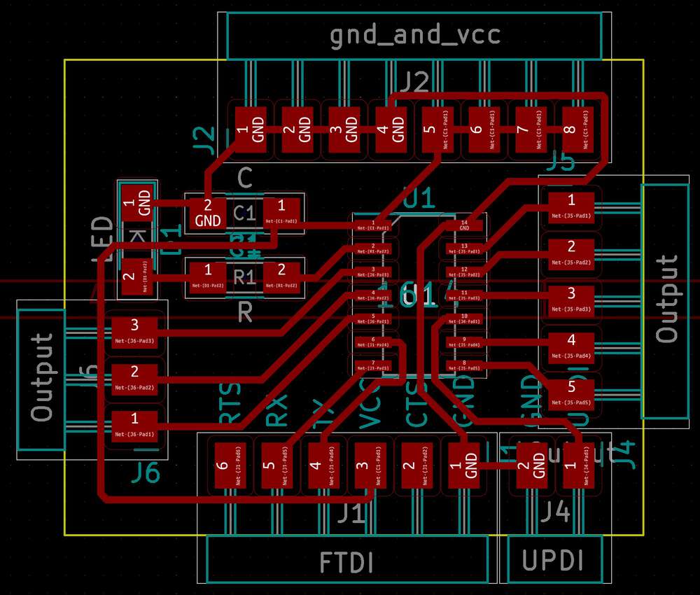
With the eight-pin 412, exposed pins were so precious that I didn’t want to tie up one of them with an LED, but I included one here. I also ditched the 3.3V regulator I used last week. I didn’t realize the lab had both 3.3V and 5V FTDI connectors, so I’d rather let my breakout be more flexible vs. having a 3.3V regulator baked in.
I milled my board, but the end mill was either totally worn down or actually broken, because it came out very gnarly.
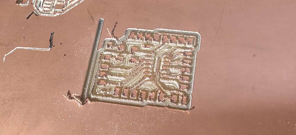
I started a fresh end mill, which is the first time I’ve done that. Neil had warned that a totally new end mill could actually produce slightly worse results than one that’s been “broken in,” but as far as I could tell it came out really nice. Except that the traces between pin 2 and pin 3 merged.
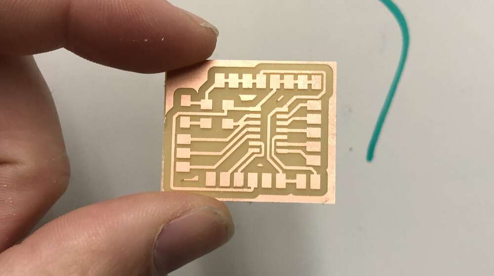
I was able to fix this merge with an exacto knife, but a lesson for me is that I should probably be using 0.5mm traces and offsets in KiCad unless I absolutely need to go down to 0.4mm. Slightly inconsistencies in producing PNGs seem to sometimes turn 0.4mm into 0.399mm.
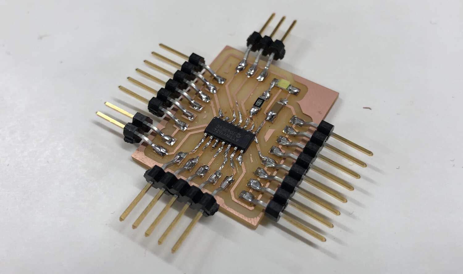
After soldering, my Reubino_v2 board was looking nice.
As per usual, I started by uploading blinky as a test. It worked! Still a delight, always.
Then it was time to get that LIS3DH accelerometer working. I connected it through VCC, GND, SDA and SCL (IC2 communication) and tried to compile the accelodemo script included in the Adafruit Arduino library. But I got this scary error.
In function `Adafruit_LIS3DH::read()'::(.text+0x13b8): undefined reference to `operator delete(void*, unsigned int)'
This is one of the cases where you just have to pray that someone else has encountered this problem and posted the solution online. And sure enough, I found one person who had!
I don’t totally understand the error but it has something to do with the AVR library for Arduino being slightly behind on its update, and thus not having access to all the functions available in C++14. The solution was to add this code to the top of my file:
#if __cplusplus >= 201402L
	void operator delete(void* ptr, size_t size) noexcept {
		operator delete(ptr);
	}
	void operator delete[](void * ptr, size_t size) noexcept {
		operator delete[](ptr);
	}
#endif
It compiled. To a 11326 byte file, which means that yeah, there was no way my Tiny412 with 4KB flash memory was going to work last week.
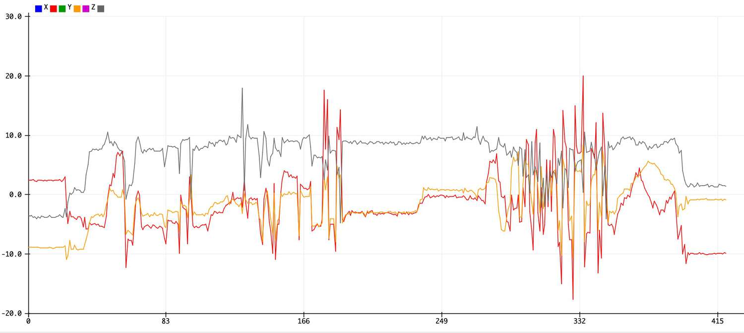
I uploaded the script and started messing around with my accelerometer. I got my serial plotter working in the Arduino IDE, and was able to visualize acceleration on the X, Y and Z axes.
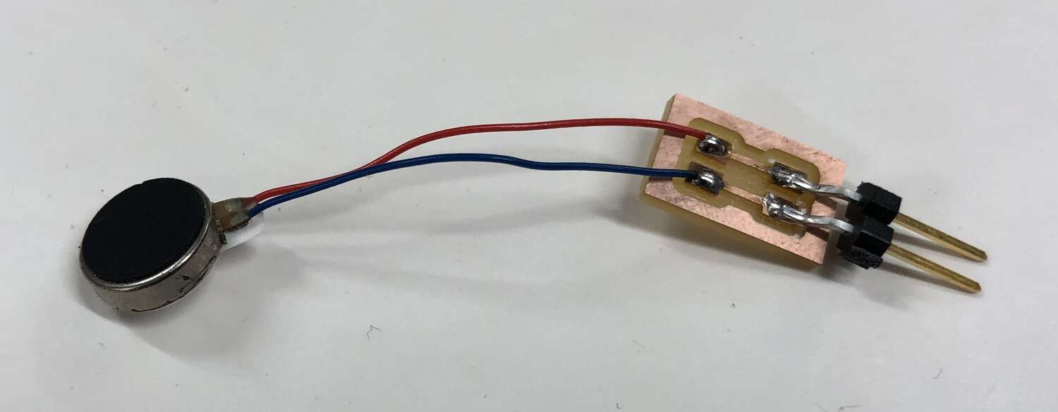
Now it was time to introduce output. We had small vibration motors in the lab, which were supposed to work fine on 3.3V. To confirm, I touched the power and ground wires to my breakout board, and it did in fact vibrate.
I designed/milled/stuff a miniature board to hold this motor. It’s my simplest one yet, just two pads for the wires and two pads for the pins. My final result:
I hooked up this peripheral to my board, and uploaded blinky. Which of course works just the same for activating a simple motor as activating an LED. Here’s motor blinky.
Now it was time to make my input and output talk to each other! For my final project, I’ll be stuffing electronics inside of a ball. So there’s no concept of “tilt” the way that a phone or flat surfaces tilts, which is a common use case for three-axis accelerometers.
I‘ll switch to a nine-axis eventually, but for now I decided to use my accelerometer to generate a single value for how much the sensor is accelerating/decelerating across all three axes. I defined that like this:
float movement =
	abs(event.acceleration.x) +
	abs(event.acceleration.y) +
	abs(event.acceleration.z);
After some fiddling around in the serial plotter, I found that a summed accel/deccel >=25 m/s was a decent measure of ”a lot” of movement. So I decided to have that value trip the vibration motors.
I uploaded the code and ... it worked! There are definitely some data lags/inconsistencies that I’d like to better understand, but here’s my motor vibrating when I shake the accelerometer.
I’d wrapped up almost all my goals for the week!
The next day, I decided I still wanted to get the entire thing hooked up to a LiPo battery. Those batteries operate at 3.7V (but can go up to 4.2V), and my accelerometer was only rated to 3.3V. Which meant that I’d need to regulate.
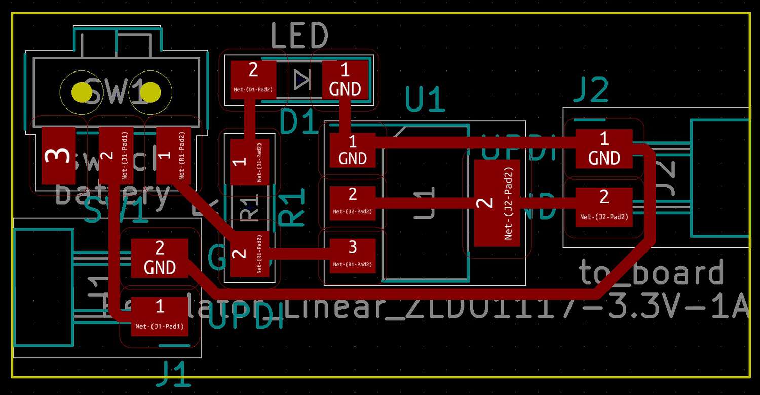
That also let me tackle a bonus goal. Eventually, I’ll want my battery power controlled by a switch. So I designed a peripheral board that regulates a power source down to 3.3V, controlled by a switch with an indicator LED. Here’s the layout. Ignore that I accidentally seleted a switch footprint with vias.
And here’s the final stuffed board:
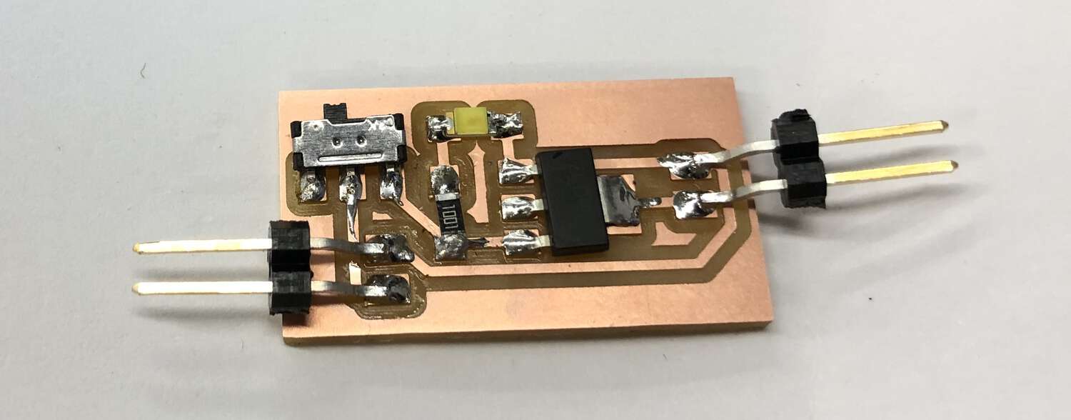
Using my regulator board, I was able to plug a LiPo battery into my breakout board, and power my three-axis accelerometer.
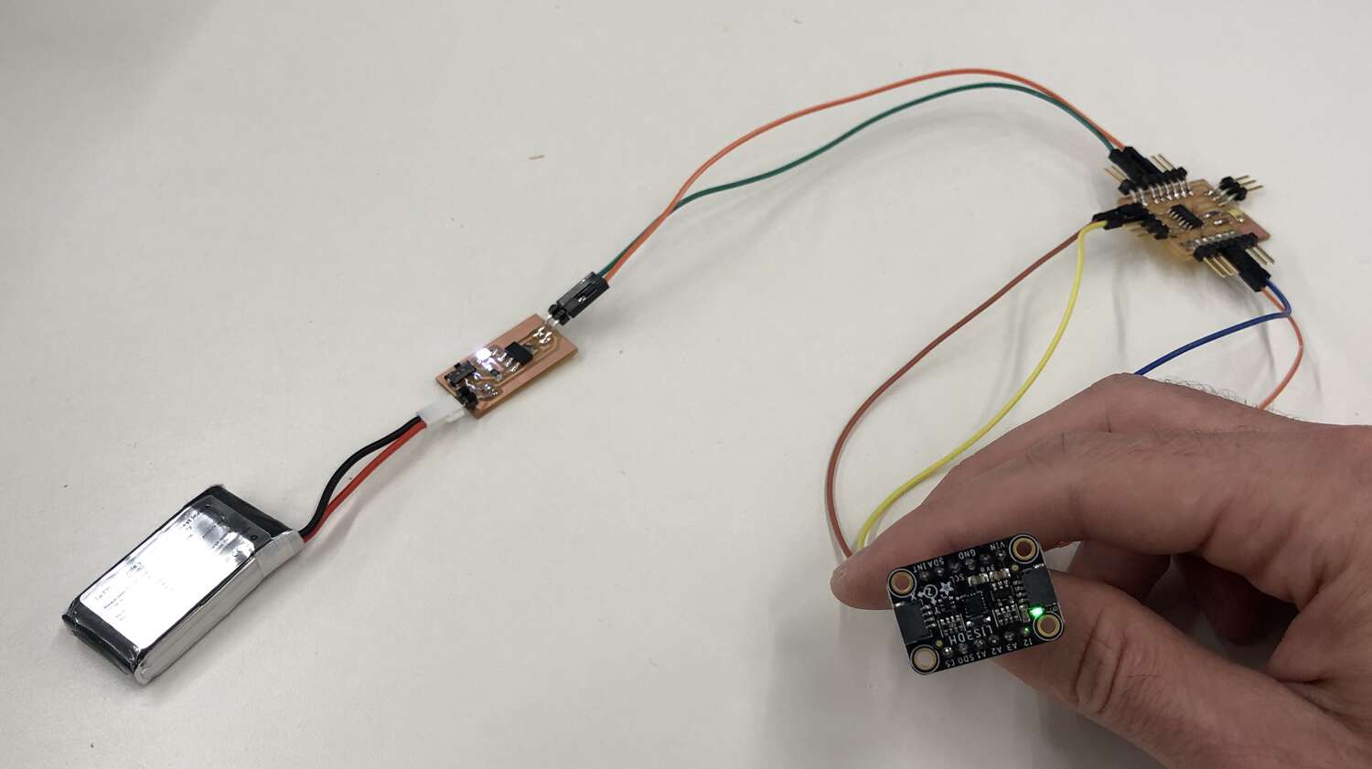
Right after I took this picture, I decided to explore the voltages on this breakout using a multimeter. But I instantly touched the wrong traces and shorted it. So my regulator board is now bricked! But the proof of concept worked I guess.
Anyways, to actually get a reading out of the accelerometer I had to plug in a serial connection ... which meant that I didn’t need an external battery anyways. A battery will make way more sense next week when I try to send my data over Bluetooth instead of setial.
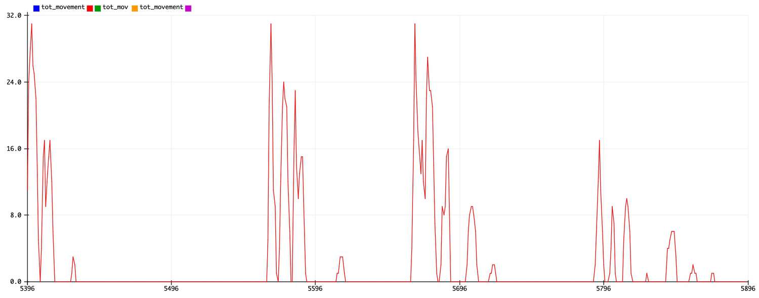
I wanted to get more useful reading out of my three-axis accelerometer, and I noticed that my “movement” variable tended to sit at around 12-15 when my device wasn’t moving. So I did a super simplifed calibration in my code by subtracting 15 from movement and then setting a minimum value of 0.
float movement =
	abs(event.acceleration.x) +
	abs(event.acceleration.y) +
	abs(event.acceleration.z) - 15;

if(movement < 0){
	movement = 0;
}
This produced something actually useful. Check out this movement detection!
One more treat for the week. It turns our lab has purchased a small number of nine-axis accelerometers (suddenly very expensive b/c of chip shortages), and I was able to snag one for my final project. Here’s the lovely Adafruit BNO055.
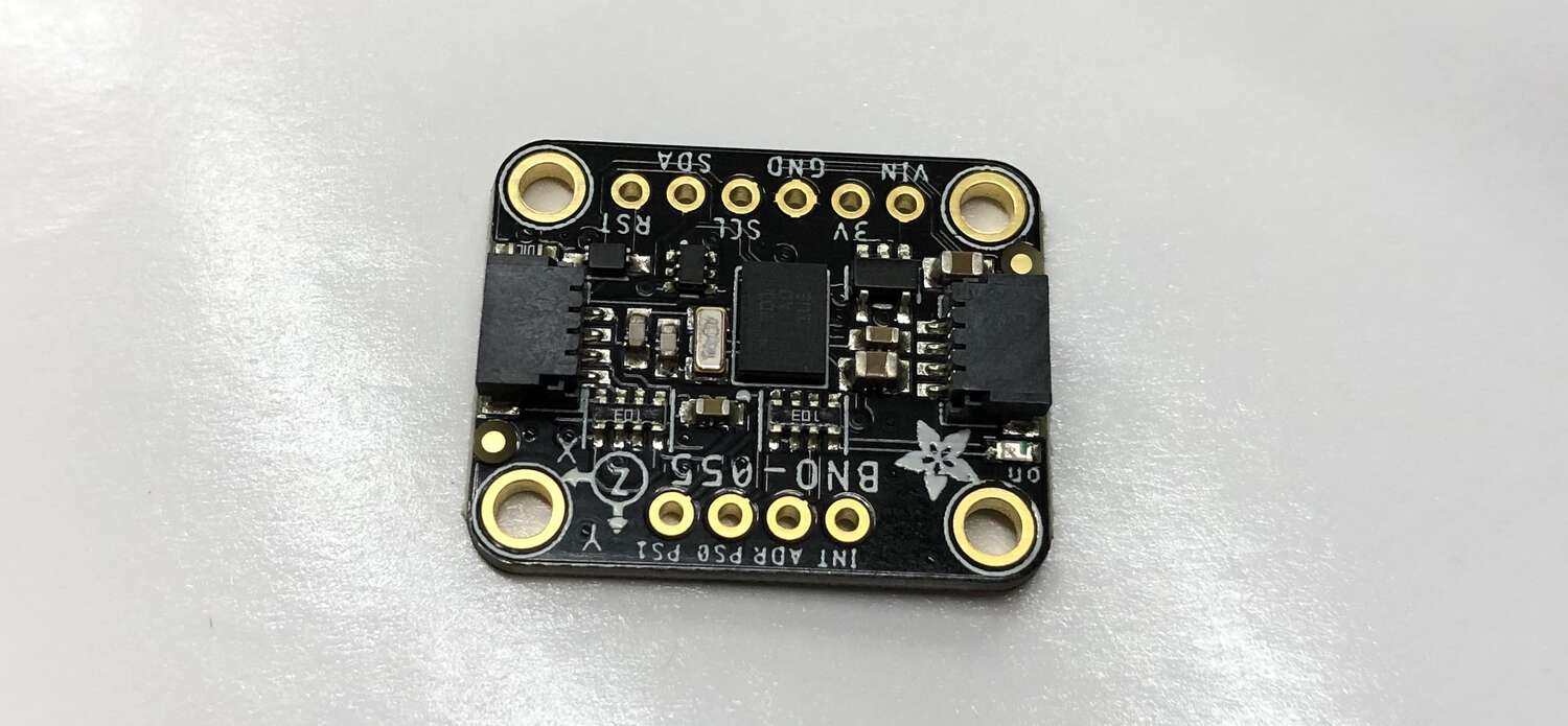
Hopefully my improved breakout board will let me wrap up networking pretty fast next week, and then I can start messing around with the nine-axis!
Files: Here are the traces and outlines for my ATtiny 1624 breakout board (with the merged paths fixed.) The vibration motor board is too simple to include (it’s just four pins), but here’s the 3.3V regulator board and the accel2vibe.ino code I wrote to use an accelerometer to trip a vibration motor, which is based on the Adafruit LIS3DH demo code.