
Another tight week for me – I’m going to be at a wedding all weekend, and I have a big writing assignment due Oct. 27. So I’m trying to speed run this week a little bit. I hope I don’t get called on!
This is actually doable, because a) I do know how to program, although not in C++ and b) I came very close to finishing this assignment back in Week 5. I got an echo script running on my custom PCB, but also a ”press the button to turn off the light” script.
However, the real focus that week was PCB design. The programming all happened with me watching over someone’s shoulder as they plugged my PCB into their computer, and I maybe understood 70% of what was going on. So my goal this week was to get that understanding to 100% by running the same scripts off my own computer, and then writing my own script.
I also decided that I wasn’t going to build a new board for this week. I’ll save that for two weeks from now, when we learn about inputs and I start to play around with accelerometers for my final project.
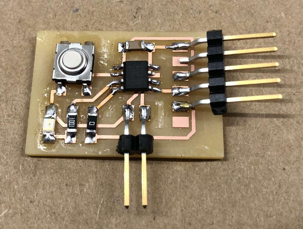
So let me reintroduce you to Spiky. He has an ATTiny412 microprocessor, an LED, a button and both UPDI and FTDI connectors.
Getting set up on my computer was actually quite easy. I downloaded the Arduino IDE, and then installed the ATTiny boards by following the steps here. To run ATTinys off of modern laptops you need a USB-to-serial converter. Luckily the Harvard Section has a very convenient converter with three output pins: Power, ground and UPDI.
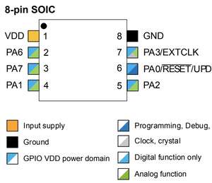
I set the IDE to an ATTiny412 board, plugged in Spiky, and set the port. To start with, I loaded up blinky (from the example in the Arduino IDE, not Neil’s script). I had to figure out what pin my LED was attached to, from Arduino’s standpoint, so I used this helpful pin diagram. (It was Pin 1.)
The code uploaded fine, and blinky worked great. Good old blinky has never let me down!
Then I moved on to the button example, where pressing the button turns on the light. My button was attached to Pin 0, but things weren’t working right. Troublingly, if I’d jiggle the button in certain ways, it would work. Which probably meant that [sad trombone] I had a hardware problem.
Sure enough, with more jiggling I was able to ascertain that my button wasn’t soldered down very well. If I pressed tightly on one of the corners of my button, I could get it to consistently work.
To fix this, I started by reflowing all the joints on my button. But still no dice. So I decided to remove the button entirely and place it again, but I really suck at removing stuff. I wicked up most of the solder and then tried to pry the button off, but I saw that I was prying off some of my traces too. So I just soldered the whole thing back on, and it still worked if I pressed down hard on it.
Look. I’m not proud of this. If I had more time this week I’d have taken a better crack a fixing my button, or maybe even made a new board.
But instead I thought: Why not turn this hardware problem into a software opportunity? I want to be able to turn my light on and off. I don’t need a button to do that, I have a UDPI connection to my computer.
I found an FTDI cord and another USB-C to USB-A converter (it’s annoying to have a Mac in ths class). That let me hook up FTDI and UPDI to Spiky, which meant that I could make sure Neil’s echo script was still working. I downloaded a Serial terminal for Mac, set it to 115200, and echo worked great!
Then I was able to modify echo.ino to create a new program that turned on the LED if you pressed Y and turned it off if you pressed N.
// This is a modification of
// hello.t412.echo.ino
//
// It lets you control an LED from a serial terminal

// Set LED pin here
int LED = 1;
int initiated = 0;
static char chr;

void setup() {
   pinMode(LED,OUTPUT);
   Serial.swap(1);
   Serial.begin(115200);
}

void loop() {

  if(Serial.available() > 0) {

    if(initiated == 0) {
      Serial.println("Type 'y' to turn on LED and 'n' to turn off LED.");
      initiated++;
    }

    chr = Serial.read();

    if(chr == "y") {
      digitalWrite(LED,HIGH);
      Serial.println("Light on!");
    }

    if(chr == "n") {
      digitalWrite(LED, LOW);
      Serial.println("Light off!");
    }
  }
}
There were a couple small challenges here. The first was getting used to the loop() structure of coding microprocessors. I had to figure out how to make sure that my printed instructions only printed once, instead of over and over. I did this by setting an initiated variable.
The second minor challenge was getting used to C++. Coming from Javascript land, I’ve become sloppy about semicolons. The compiler was not happy!
Just to make use of FTDI connector, I had Spiky report whether you just turned the light on or off. I loaded up my program, and ta da!
With that, I’m going to call it a week on the programming portion of this assignment. Certainly I could have tackled something more ambitious, but I’ll take some easy victories where I can get them.
Starting next week, HTM(A)A becomes the only class I’ll have a lot of work for the remainder of this semester. And it’s great timing, because starting with molding and casting, I should be able to have all the weeks to come be in service of my final project. Looking forward to it!
I spent eight hours in the car this weekend, so I also got a chance to skim through the ATTiny 212/412 data sheet. As someone who doesn’t understand how computers function super well, I wouldn’t say it was the easiest thing too follow. I did enjoy the pin diagram, but I’d already used that back in Week 5.
And then sadly, I learned later this week that there’s actually a shortage of ATTiny microprocessors because of supply chain issues. So going forward, it’s recommended that we use the SAMD11s instead, which will probabably be the basis for the PCBs I make for inputs/outputs/final project. So all my skimming was for naught!
Files: For blinky and blinky button, the only tweaks compared to Arduino example scripts were my pin assignments So I think the only script worth looking at is who_needs_a_button.ino.