Overview
Workload: ● ● ● ○ ○
Previous Knowledge: ○ ○ ○ ○ ○
Current Knowledge: ● ● ○ ○ ○
Concepts
Programming, Debugging
Software
Arduino IDE
Assignments
1. Browse through the data sheet for your microcontroller
2. Use your programmer to program your board to do something
3. Compare the performance and development workflows for other architectures [Group]
Extra credit: Try other programming languages and development environments
Documentation
This is the third week about electronics. As it happened in the last one - Electronics Design, this has been a very challenging assignment, especially because of my shallow knowledge about electronics in general.
Theory
Before starting the assignment, I took some time to read material recommended by the teaching team.
Embedded Architectures Recitation
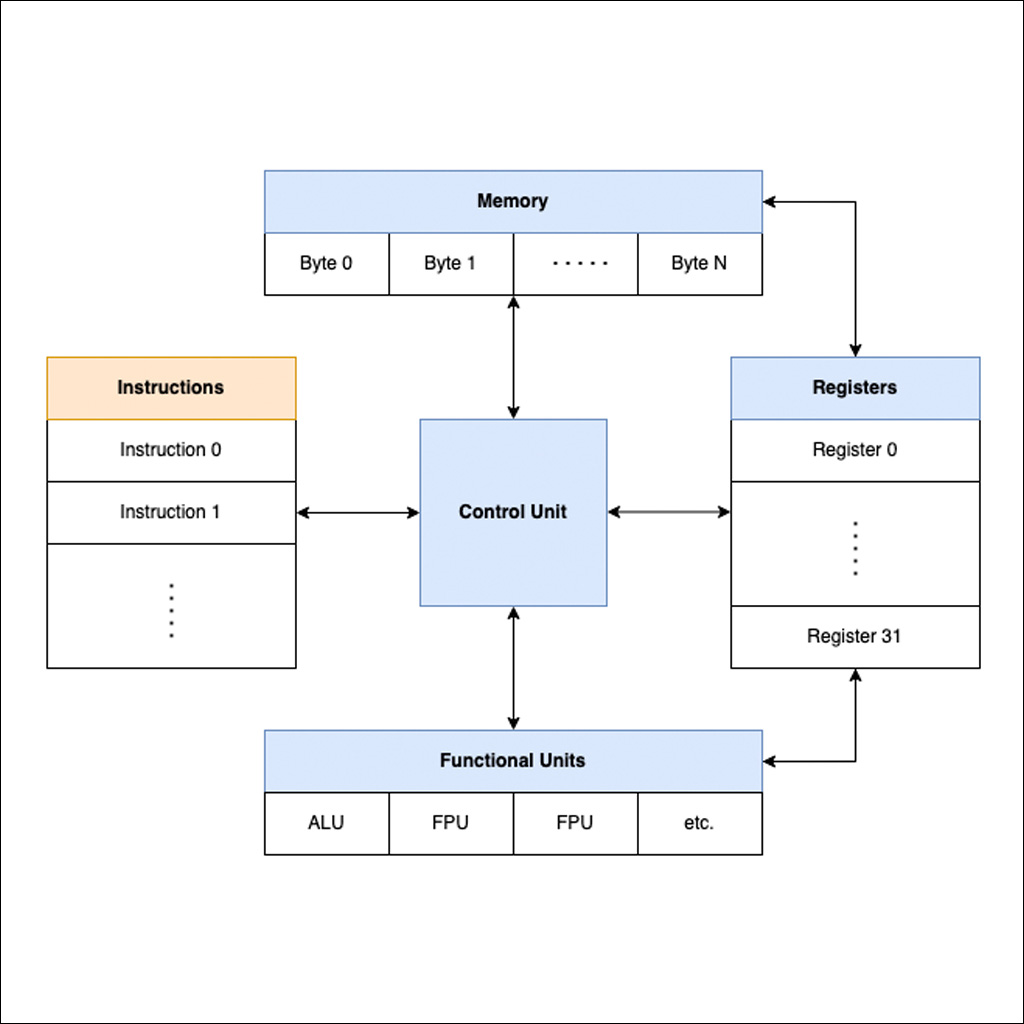
What's Inside Your Microcontroller?
Nearly all computers have the same core components:
• Memory: used to store data (just a big array of bytes - unit of digital information that consists of 8 bits)
• Functional Units: responsible for performing simple computational primitives. Almost all computers have an arithmetic logic unit (ALU) that handles adding, subtracting, multiplying, and dividing integers. Fancier microcontrollers (as well as any modern phone, laptop, or desktop processors) also have one or more floating point units (FPUs) that handle floating point arithmetic.
• The control unit: reads a sequence of instructions from memory, and executes them by dispatching to the relevant functional units.
• Registers: another form of memory with a special purpose: they provide a very limited amount of memory that the functional units can read directly.
The Practical Microcontroller Primer
What is a Microcontroller:
Basically these tiny devices (chips, uCs, micros, etc) are little baby computers. They tend to not run operating systems (like your laptop / pc / phone does), and contain much less compute power / memory.
Additionally (and the whole reason for our bothering with these things) microcontrollers have peripherals - these are smaller, special function circuits that the computer-part of a microcontroller can interact with (via special function registers, more later) in order to operate on the physical world: setting voltages on external pins, reading and writing data to networks, reading data (or voltages) from sensors - etc. The microcontroller is our bridge between computing on data and computing on physical stuff.
How we communicate with them:
What we write a program in is a human-readable representation of what actually happens, which is that various numbers are shuffled around in the microcontroller’s memory, using the microcontroller’s brain. When we compile our code, it is transformed from this human-readable representation into the fabled “string of 1’s and 0’s” that the computer can operate on.
The “string of 1’s and 0’s” is what we call a binary file normally in .bin or .hex naming convention. In order for the microcontroller to operate on this binary file (and thereby run the program we’ve written) we need to load it into the microcontroller’s nonvolatile (normally flash) memory. This is why we often call programming a micro “flashing” it.
Programming:
When we get a chip from the factory, that memory is empty and so the microcontroller doesn’t do anything. We need to write our freshly-compiled binary file (or a pre-compiled bootloader, or firmware update) into the memory, kind of like how we would write a file onto an SD card.
In order to do so, we need a relatively low-level data-writing protocol between our computer (where we’re compiling code / having binary files) and the microcontroller. The operation of these protocols is baked into the micro’s hardware and so it’s always available, but we normally need another tool in order for our computer to speak these protocols: most PCs have USB built-in, but not JTAG SWD or ISP etc.
Different chip families use different debug protocols, I’m keeping a list here of what you can expect to find in each family, including links for where you can purchase (or build) these tools, and pinouts! (e.g., ATSAMD11 - SWD, JTAG; ATtiny - ISP)
Toolchains: So in full order, we use a compiler to write a binary file, then use a programmer to write that binary file into the microcontroller. Together, these things constitute a toolchain - any sequence of tools used to turn code into a piece of operating firmware.
Bootloaders: Bootloaders are like “programming programs” (we love a little recursion, as a treat) or “flashing programs” - they’re bits of code that we stick in our microcontrollers that run for just a few ms at boot-up to check if there is a new program to load, and then loads it if this is the case. In this way, they “bootstrap” a program into their own memory.
Additional Information (other sources)
A microcontroller (or MCU) datasheet explains the component capabilities, electrical and mechanical characteristics, and the peripherals it has and how to interact with those along with the register interface it provides. It includes list of features, electrical specifications, some basic hardware-implementation examples, pin definitions, and footprint dimensions.
Usually, datasheets are very detailed and, as microcontrollers become increasingly sophisticated and powerful, they become longer and more complex. These are some important information to focus on:
• Overview of the Device: The first thing that you should look for in the datasheet is the overview or summary of the device. This should take up the first or first two pages the datasheet even before the table of contents.
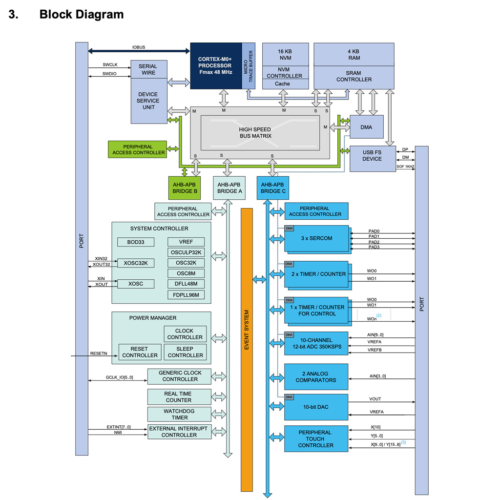
• Block Diagram: You can use this to get a quick idea of how different parts of the microcontroller can communicate. As a beginner you probably won't need to look at it too much..
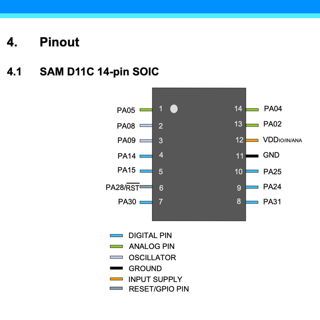
• Pin Diagram: Check out the pin diagram for your package. This is especially needed if you are looking for a compatible replacement for a component. If you plan to use one device for all your development, then I suggest you take a print out of the block diagram and stick it on to the wall near your soldering iron.
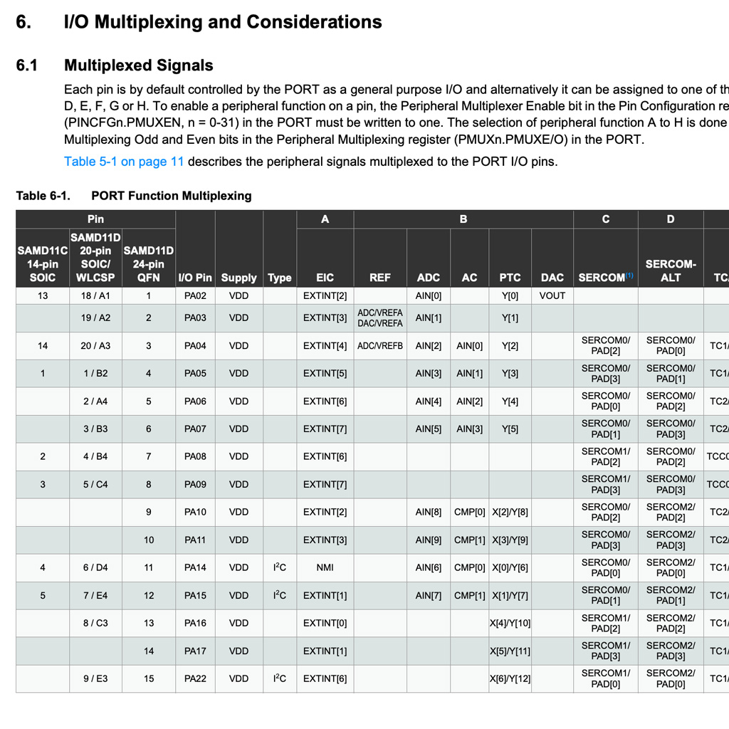
• I/O Multiplexing: This section is helpful when you're planning a project. Certain peripherals need to use certain pins, so it's possible to end up in a situation where your microcontroller has enough pins in total, but you still have a conflict since you wanted to use two different peripherals that both want to make use of the same pin. Most peripherals give you a couple different pin options, so sometimes it take some thought to determine if there's a way to assign pins without any collisions.
• Peripherals Each peripheral gets its own section. These chapters are gold when you're trying to get up to speed with a certain peripheral. (some common ones are: PORT, TC, ADC, DAC, SERCOM, I2C, SPI, CCL)
• Application Circuits: In almost every datasheet, there is a section that deals with the application of the device. It might just be a description or it might have a detailed circuit with explanation. It must be made a practice to see this regardless of whether you are going to be making the hardware yourself or buying it prebuilt. This knowledge will help when things get a little messy and you have to debug the circuit.
• Absolute Maximum Ratings: The absolute maximum ratings are really important as they give you an idea on when your device will be bricked/fried! The manufacturers go to great extents in describing the behavior of the chip at various operational parameters such as voltage, current, temperature and pressure.
• Timing Diagram: The timing diagrams are mostly used for illustrating protocols. They help us visualize the state of the pin with the timer interval. It comes in handy when you sit down and start writing low level drivers for hardware protocol.
Practice
Reading the Datasheet
Since first week, I've been using the following microcontroller:
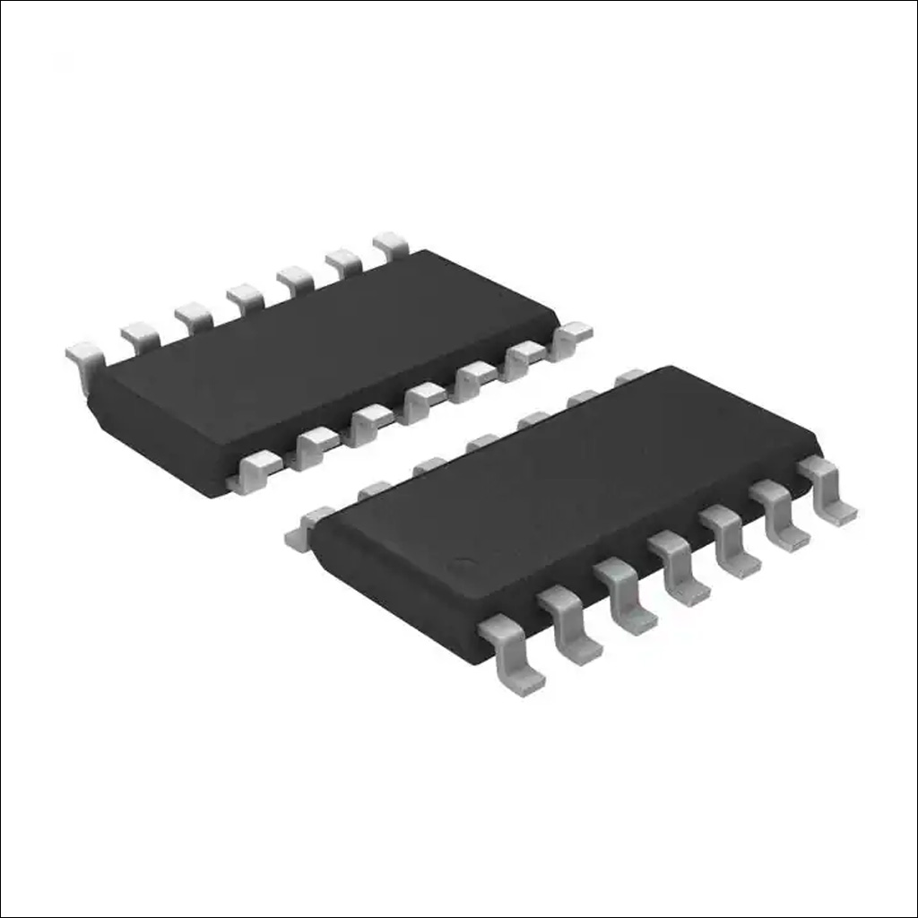
Model: ATSSAMD11C
Data Sheet: Link
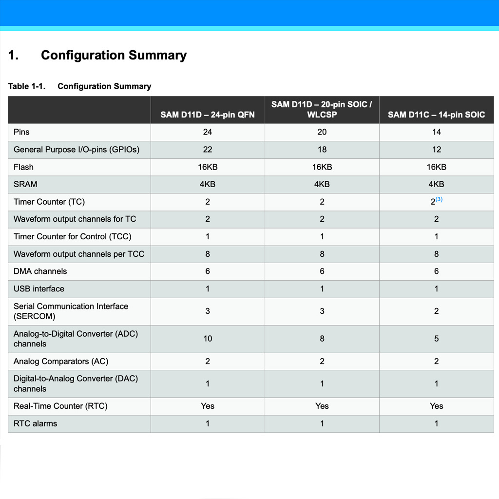
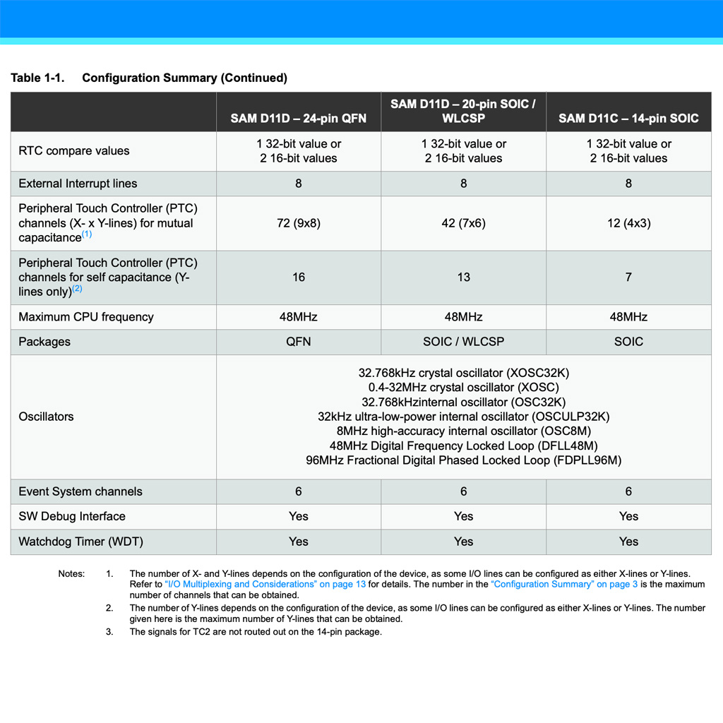
1. Following instructions from the readings indicated above, I found some important sections in the datasheet:
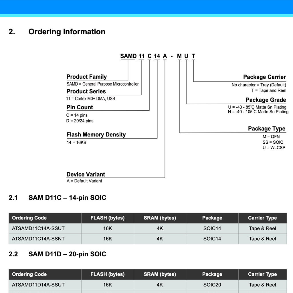
• Overview:
• Block Diagram:
• Pinout:
• I/O Multiplexing:
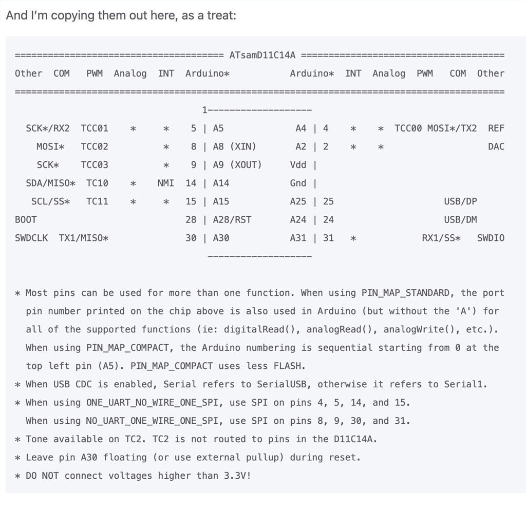
* In the The Practical Microcontroller Primer, there is a very useful diagram of some popular microcontrollers. It includes very important information (e.g., Arudino pins, Analog, etc.) with a more simple structure.
Programming the Board
For programming, I used the boards I created in Week 03 (as a programmer) and Week 05 (to perform a function).
1. First, I had to use the bootloader to load initial information and later be able to use the USB to program my board.
I followed the EDBG Tutorial and flashed my programmer.
2. Then, using the pogrammer and the 10-pin connectors, I flashed my second board
3. With that, I was able to work in Arudino IDE to load the code in the second board and define what action it should perform. To do that, you have to follow the Arduino Setup Guide.
After choosing the board and the port, I loaded the code and could see the LEDs turning on.