Overview
Workload: ● ● ● ○ ○
Previous Knowledge: ○ ○ ○ ○ ○
Current Knowledge: ● ● ○ ○ ○
Concepts
Input components/sensors (switch, magnetic, step response, temperature, light, motion, sound, etc.), programming
Software
EAGLE, Mods, Arduino
Assignments
1. Measure something: add a sensor to a microcontroller board that you have designed and read it
2. Probe an input device's analog levels and digital signals [Group]
Documentation
This has been one of the weeks with more disappointing moments, but also some important learnings. Electronics is clearly the subject that challenges me the most and I struggle a lot with every simple step given my background and essentially no previous knowledge. Also, I tried to build a too complicated board in the beginning, creating challenges I could avoid, but I ended up with a much better understanding about concepts I should have learned about in the previous assignments (i.e., read the data sheet, find the right components and pins, programming, etc).
Planning
1. First, I had to decide which type of component I would use from a long list of input devices that measure different types of information - magnetic field, potentiometer, step response, temperature, light, motion, distance, location, time, acceleration, orientation, rotation, sound, vibration, force, angle, pressure, pulse, air pollution, gases and image.
Since this is not a straightforward week for me, I wanted to create something that could be easily applied in my final project. So I decided to focus on the light feature I want to include in my desk - basically, the lights in the desk should vary their intensity based on the ambient's light.
My initial idea was to create a board with:
• A light sensor: to measure intensity and tone from the ambient light.
• A LED: to emit light based on the measurement from the sensor.
* The LED was not necessary for this assignment, but I wanted to create a board that could be used next week (Output Devices) and also test if my idea made sense for final project.
2. Looking at the sensors available for measuring light, I chose an RGB sensor because it not only measures the intensity but also different colors.
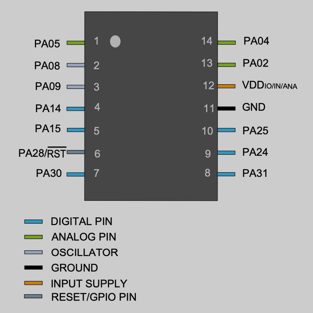
Also, I wanted to keep using the same microcontroller (SAMD11C) I've used in the previous weeks since it had enough pins and I though that would help during the board design.
So these were the components I planned to use:
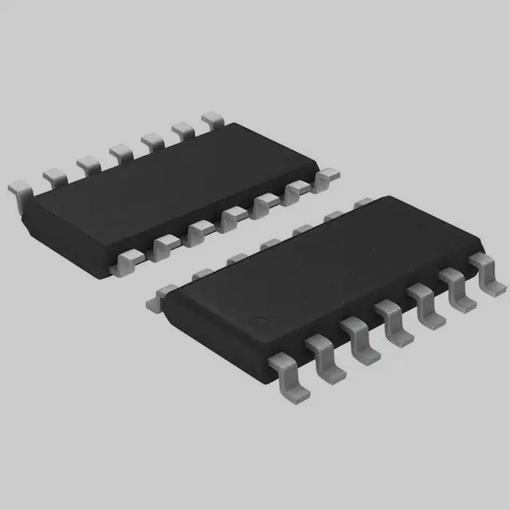
• Microcontroller:
Model: ATSSAMD11C
Data Sheet: Link
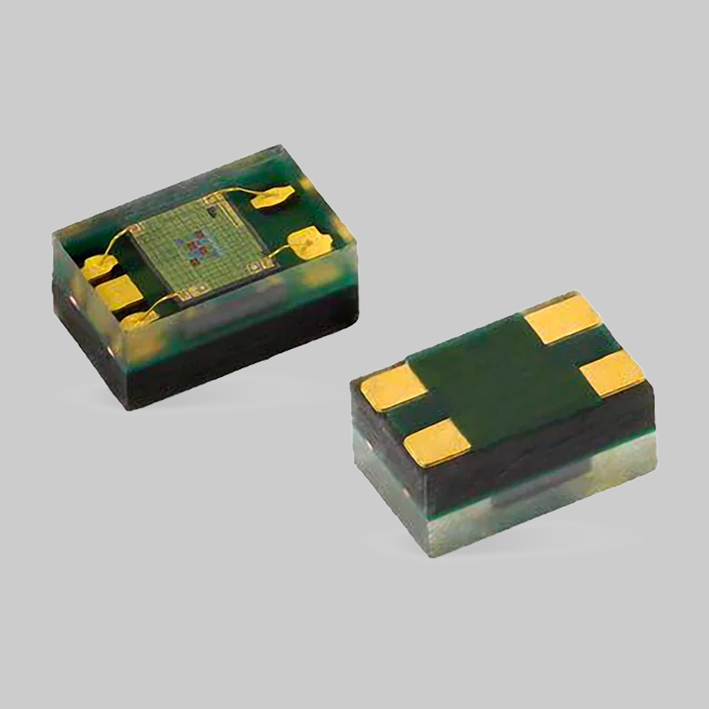
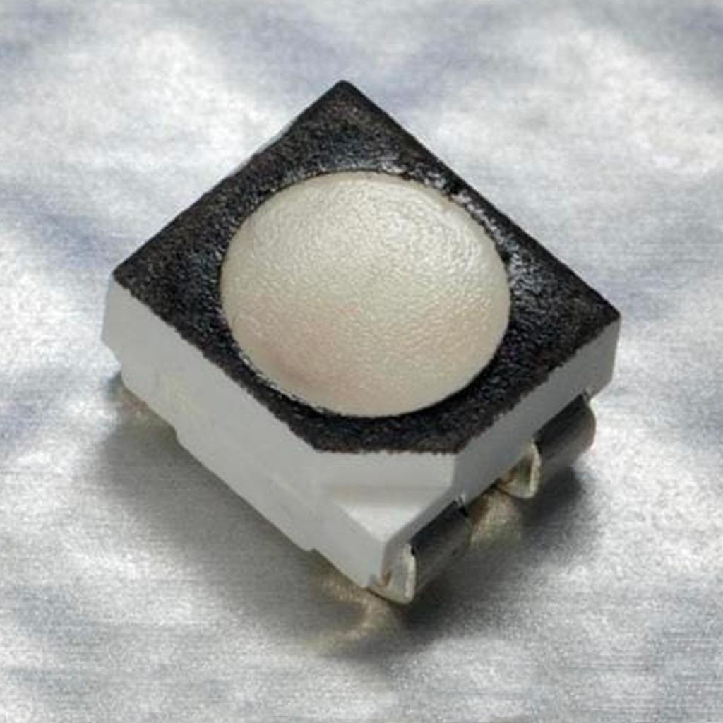
• RGB sensor:
Model: VEML6040A3OG
Data Sheet: Link
• A RGB LED:
Model: CLV1A-FKB
Data Sheet: Link
• Button: I added a button in order to control when the light should be turned on.
• Voltage Regulator: to control voltage (5V to 3.3V)
• Capacitors: required for both the microcontroller and RGB sensor.
• 10-pin Connector:physical connector to initially program the board
• USB Connector: to connect to computer.
• Resistors: for LED, pull up resistor for the sensor and 0ohm to bridge traces
Designing
Again, I used EAGLE (in Fusion 360) to design my schematic PCB and generate the .png that will be used to mill the board.
First, I had to understand where to connect each pin and with specific components were necessary (e.g., resistors, capacitors, etc.).
This was a very challenging step for me. After attending the office hours and asking for many people, these were some important learnings and resources:
1. Look for I/O Multiplexing table in the microcontroller data sheet. It contains the types of connector and details about each pin.
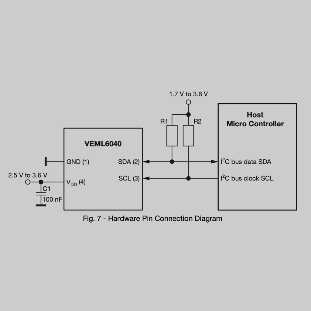
2. Look for the schematic in every component data sheet. This is very useful for finding which additional components (resistors, capacitors) are required. For intansce, the sensor requires 2 pull up resistors and a 100nF capacitor.
3. Read The Practical Microcontroller Primer: a simplified guide that includes a lot of summarized information for some popular microcontrollers.
4. Search for the Arduino library for the components. In this case, I used this one for the VEML6040 sensor.
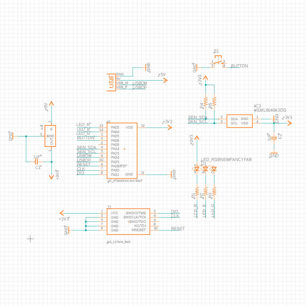
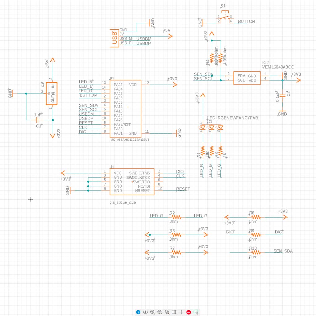
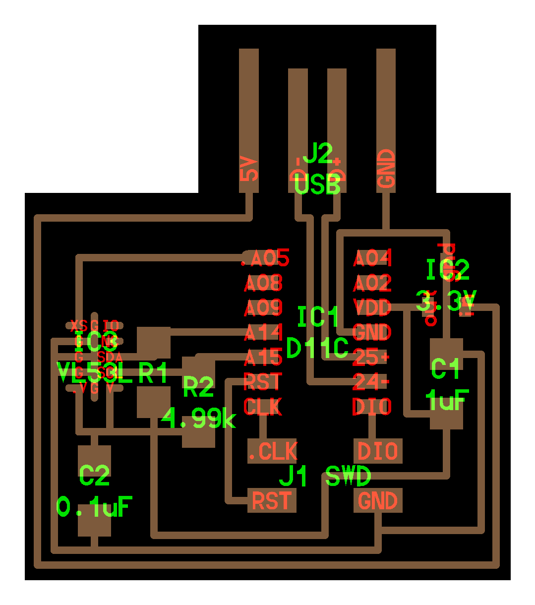
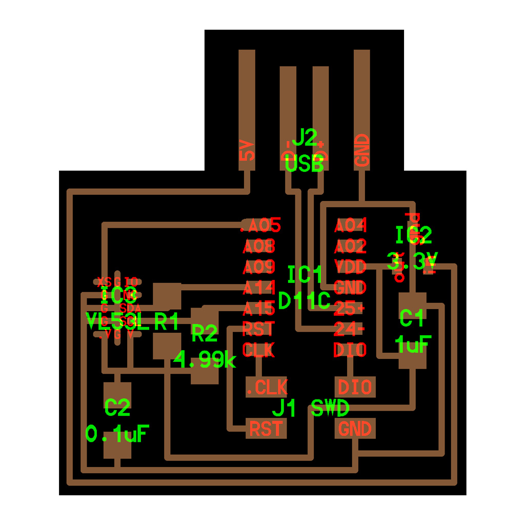
2. Then, I created the schematic on EAGLE.
*The RGB sensor component was not available in the Fab library, but I found it on Component Search Engine.
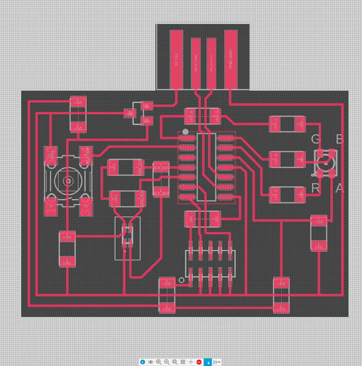
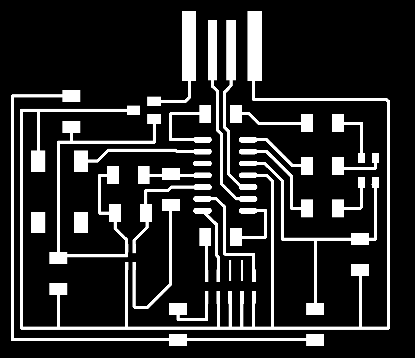
3. The next step was to design the traces on the actual board view. This was the moment in which I realized that I had chosen a structure that was to complex for me. These were some of the issues:
• There were too many connections and traces crossed multiple times. I spent several hours trying to figure out a good placement for the components, but ended up with 6 0 ohm resistors and a design that was more complex than what I wanted
• The sensor was not available in the fab library. I downloaded from Component Search Engine. and uploaded to my own file.
• The gap between the pins in the RGB sensor was very small and it was not possible to mill it using a 1/64" bit. To solve this, I adapted the footprint and move the pins a little
• Both the RGB Sensor and the RGB LED required soldering reflow.
After a lot of time and help from multiple TAs, I ended up with the following design:
Producing
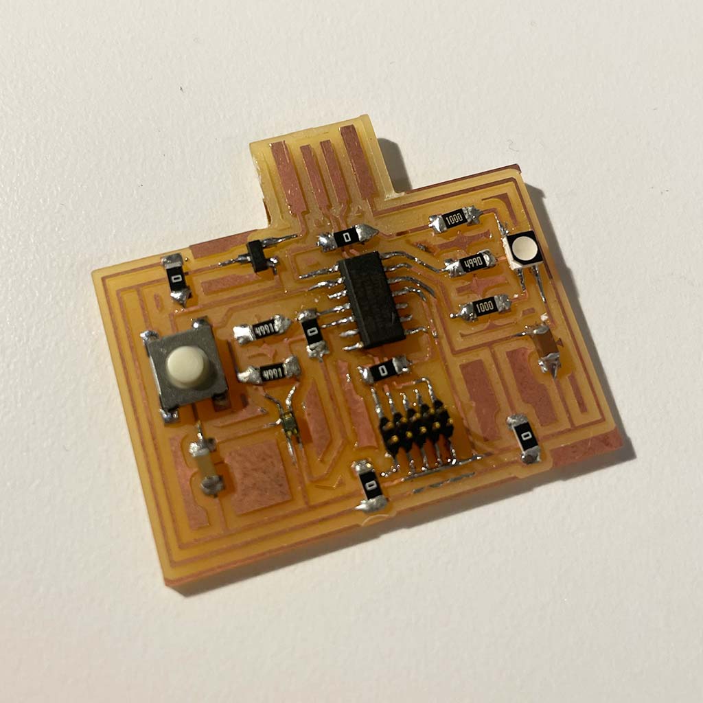
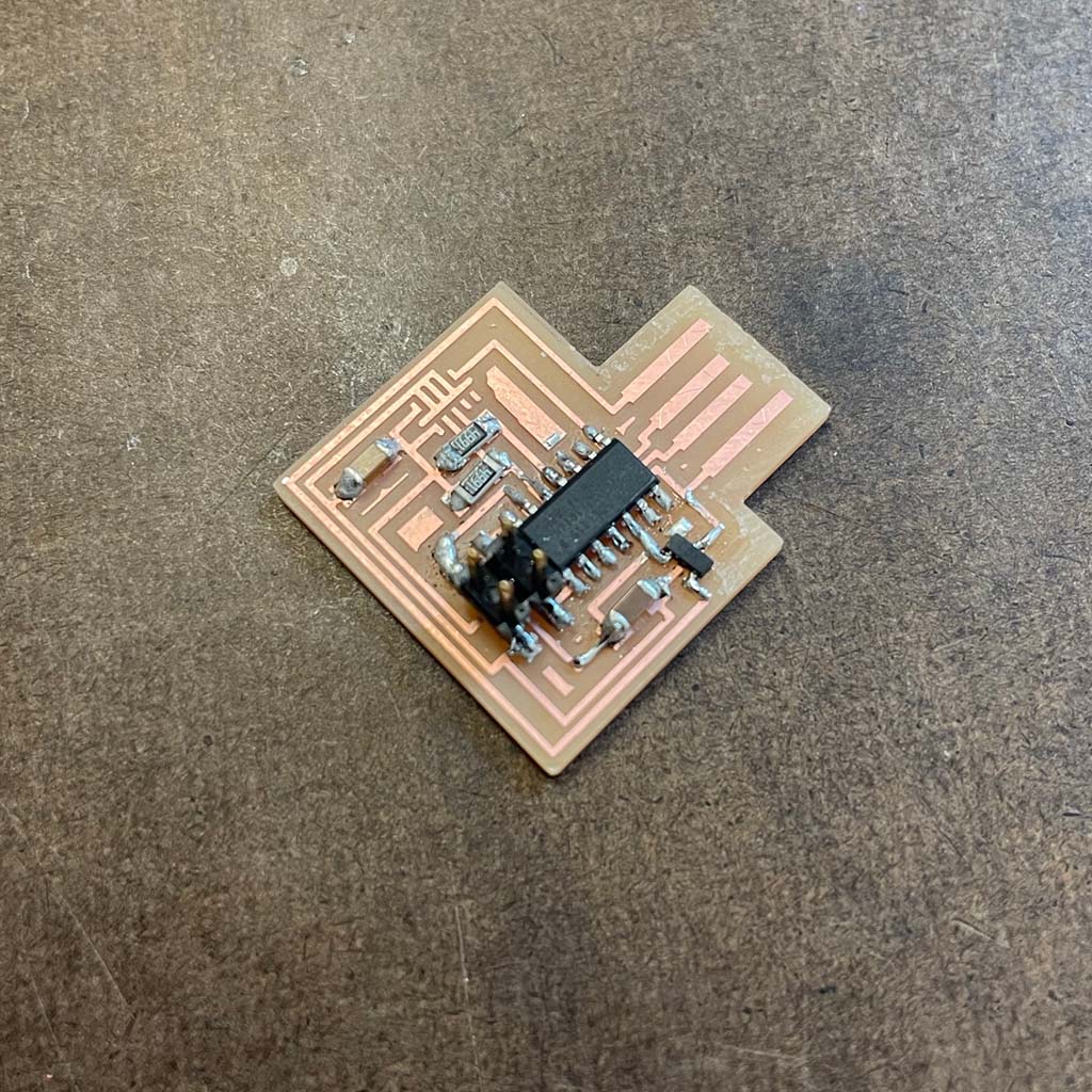
[Update from Week 10] Since I took to long to design the board, I was able to mill it only on Week 10.
All steps are described in that page and this was my final board:
Programming
1. To program the sensor, I had to find the VEM6040 Arduino Library.
Then, I followed the instructions and installed it.
2. I uploaded the auto_mode, but got the following error.
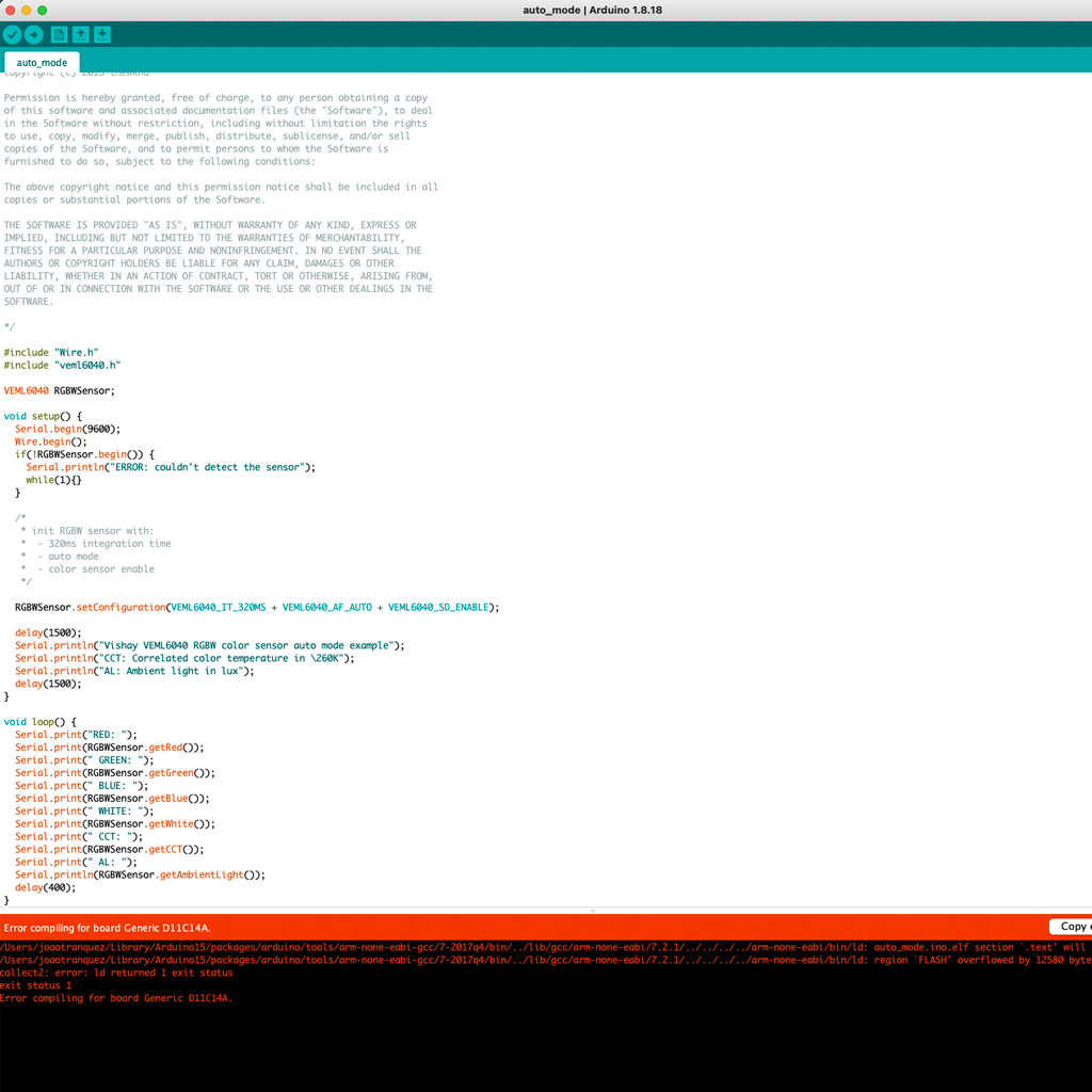
After debugging with the help of one of the TAs, we realized that there was an issue with the I2C connection, so there might be no communication between the sensor and the microcontroller.
It is likely that the component was not soldered properly or got burnt during the soldering reflow.
Unfortunately, I couldn't test the sensor, but I'm planning to create a new board and include it on my final project.
Backup Plan
At a given moment, I realized that I would not be able to finish all the assignment moving forward with my own board.
Then, I decided to try milling and programming a board that was already available in the class website.
Planning and Designing
I chose the hello.VL53L0X.D11C. First, because it had the distance sensor, which might be useful for the final project. Second, because it uses the same SAMD11C Microcontroller and the learning would help me in the future with my own board.
Producing
1. I used the .png files and successfully milled the board. Also, I soldered all the components, except the sensor, which required soldering reflow.
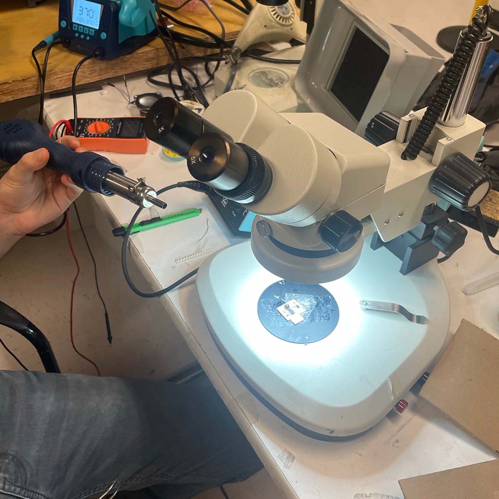
2. For the reflow, I asked for help and, using the microscope and a heating gun, I finally got my sensor soldered to the board.
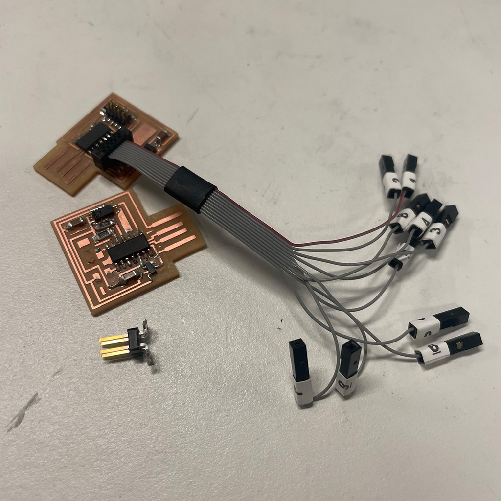
3. However, when I tried to connect to bootload the board, I accidentally broke the pin connector and remove part of the copper trace.
As I mentioned, this was the week with a lot of mistakes. I had many challenges while designing and producing the board and couldn't make it work properly.
However, there were great learnings, specially to consolidate some skills that I started to develop during previous weeks, but didn't have enough time to practice. For instance, I became better on selecting the right components for the work I wanted to do, finding information on datasheets and other sources, designing the board on EAGLE and even soldering more complex components. I look forwarding to testing more board over the following weeks.
Files