Overview
Workload: ● ● ○ ○ ○
Previous Knowledge: ○ ○ ○ ○ ○
Current Knowledge: ● ● ● ○ ○
Concepts
Output components (LED, display, speaker, solenoid, motor, etc.), programming
Software
EAGLE, Mods, Arduino
Assignments
1. Add an output device to a microcontroller board you've designed, and program it to do something
2. Measure the power consumption of an output device [Group]
Documentation
This week, we had to design a board with an output device and program it. Although electronics is still very challenging for me, it was good to have more time to learn about more it and keep working in the same idea for more than just a week.
Given that I had designed a board with both input and output components for last week's assignment, I decided to keep the same project and try to correct previous issues and finally be able to program something I created.
Planning
1. Choosing components: There were several output components available to us - RGB LED, LED, LED array, displays, video, speaker, DC motor, servo motor, brushless DC motor, stepper motor, etc.
Given all the challenges I've had with electronics, I decided to keep working in the same design gives that it included an RGB LED.
As mentioned in Week 09, my goal was to include:
• A light sensor: to measure intensity and tone from the ambient light.
• A LED: to emit light based on the measurement from the sensor.
* The sensor is not necessary for this week, but my goal was to learn how to make these components interact and also try to finish previous assignments.
2. Describing components: The components I planned to use are exactly the same:
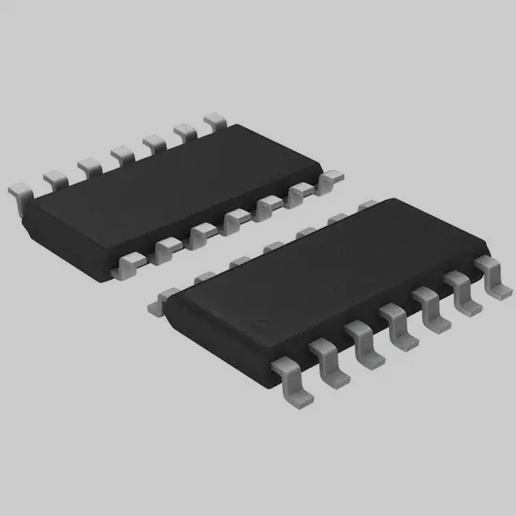
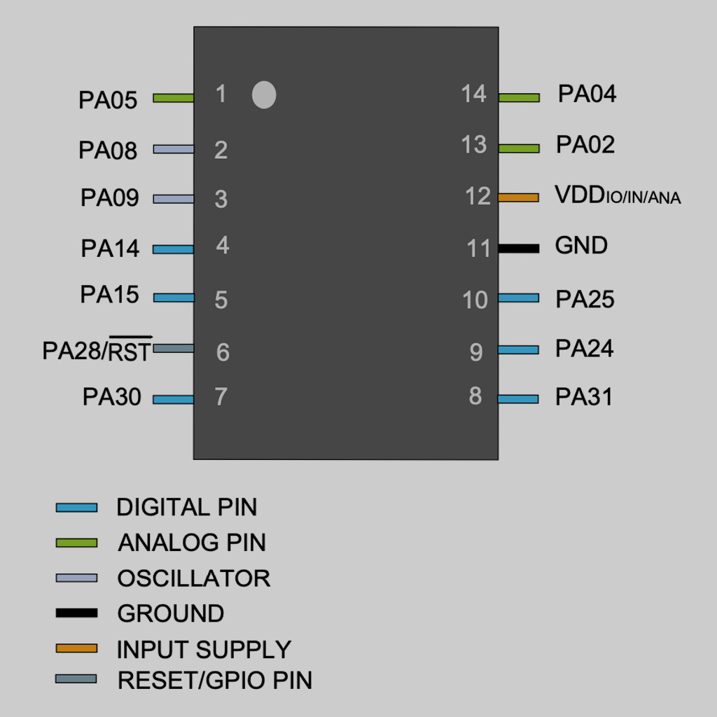
• Microcontroller:
Model: ATSSAMD11C
Data Sheet: Link
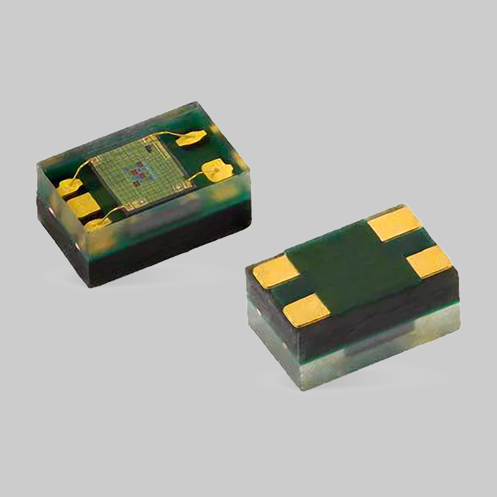
• RGB sensor:
Model: VEML6040A3OG
Data Sheet: Link
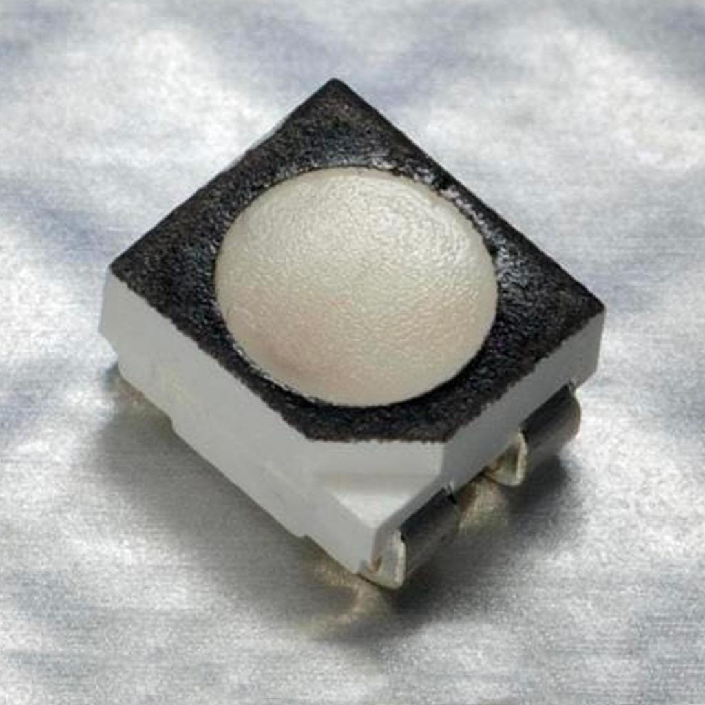
• A RGB LED:
Model: CLV1A-FKB
Data Sheet: Link
• Button: I added a button in order to control when the light should be turned on.
• Voltage Regulator: to control voltage (5V to 3.3V)
• Capacitors: required for both the microcontroller and RGB sensor.
• 10-pin Connector:physical connector to initially program the board
• USB Connector: to connect to computer.
• Resistors: for LED, pull up resistor for the sensor and 0ohm to bridge traces
Designing
Below, I described the same details and learnings from last week:
1. Preparing: First, I had to understand where to connect each pin and with specific components were necessary (e.g., resistors, capacitors, etc.).
Some useful resources:
1. Look for I/O Multiplexing table in the microcontroller data sheet. It contains the types of connector and details about each pin.
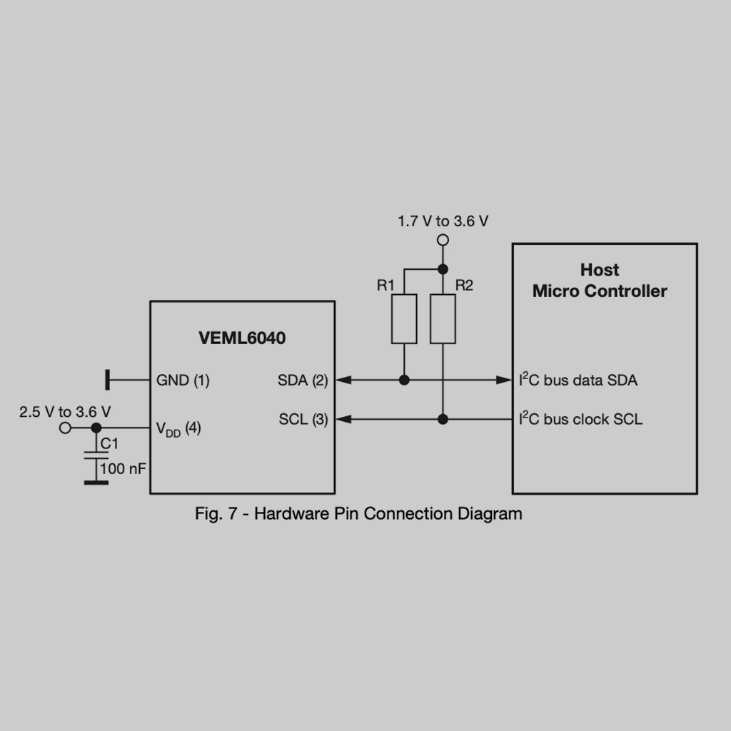
2. Look for the schematic in every component data sheet. This is very useful for finding which additional components (resistors, capacitors) are required. For intansce, the sensor requires 2 pull up resistors and a 100nF capacitor.
3. Read The Practical Microcontroller Primer: a simplified guide that includes a lot of summarized information for some popular microcontrollers.
4. Search for the Arduino library for the components. In this case, I used this one for the VEML6040 sensor.
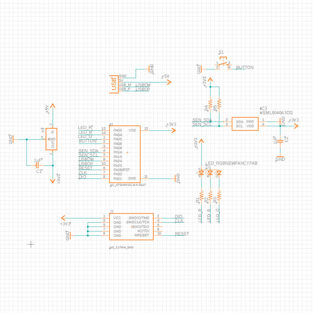
2. Designing on Fusion 360: Then, I created the schematic on EAGLE.
*The RGB sensor component was not available in the Fab library, but I found it on Component Search Engine.
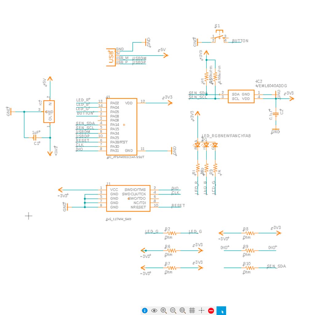
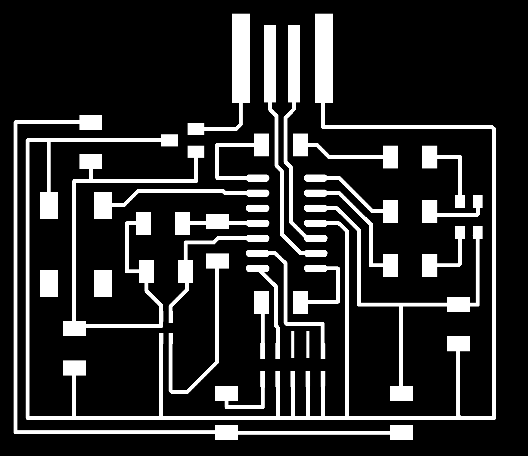
3. The next step was to design the traces on the actual board view.
• There were too many connections and traces crossed multiple times. I spent several hours trying to figure out a good placement for the components, but ended up with 6 0 ohm resistors and a design that was more complex than what I wanted
• The sensor was not available in the fab library. I downloaded from Component Search Engine. and uploaded to my own file.
• The gap between the pins in the RGB sensor was very small and it was not possible to mill it using a 1/64" bit. To solve this, I adapted the footprint and move the pins a little
• Both the RGB Sensor and the RGB LED required soldering reflow.
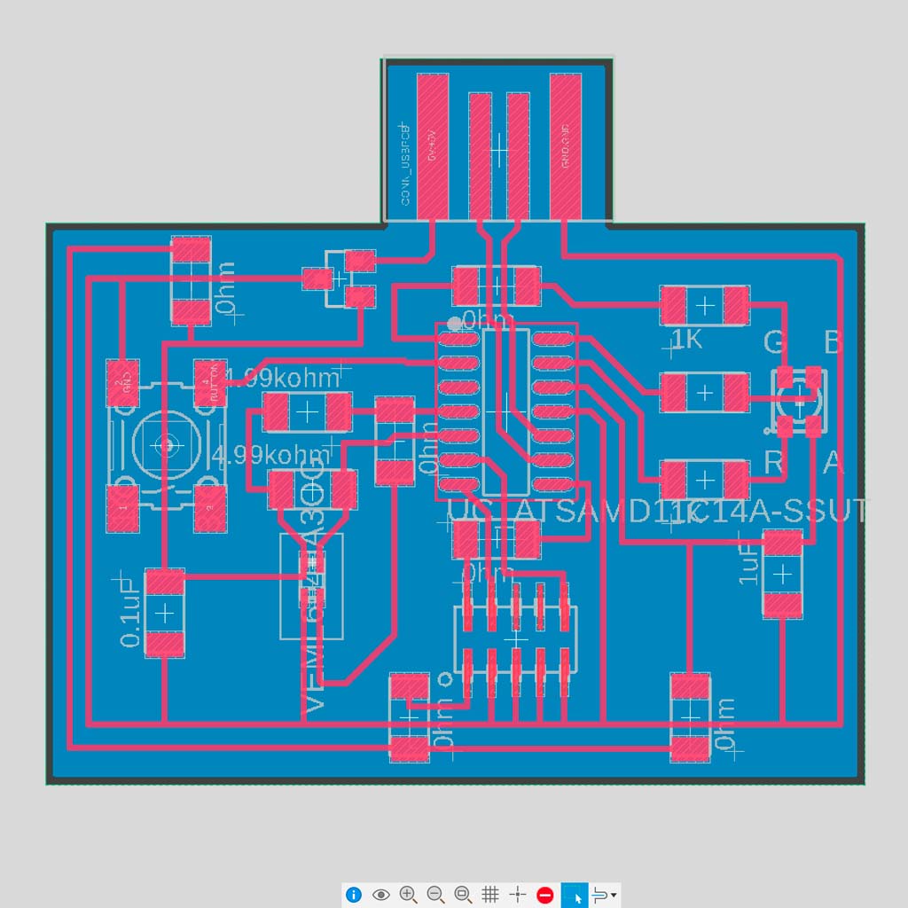
Compared to last week, I made some minor changes. For instance, I made some pads a little bigger and move some traces further from one another in order to make the soldering process easier. This is the final design:
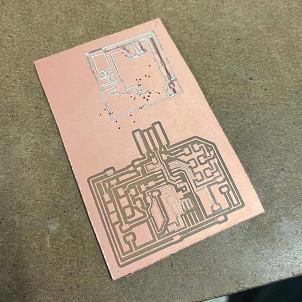
Producing
1. Milling: The first step was to mill the board. Again, there were a few issues, mainly related to the right reference for the z-axis. Probably because the blank board was not flat, the middle part was not fully milled:
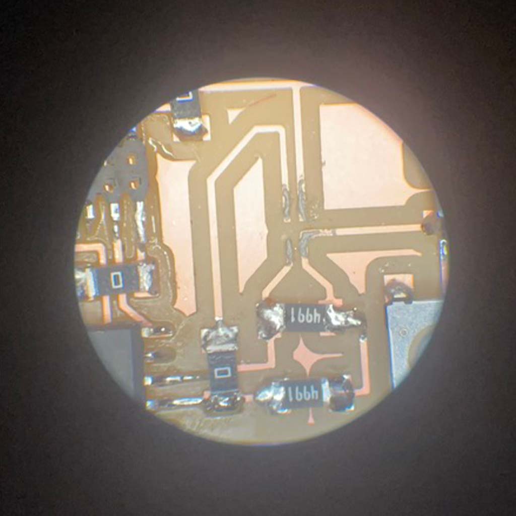
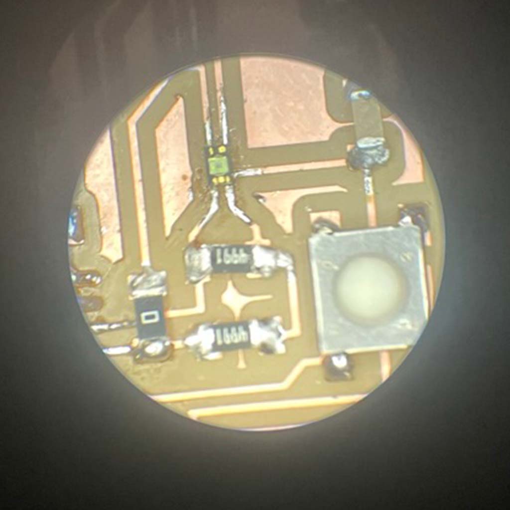
2. Soldering: Then, I had to solder all the components. After one more mistake (I soldered the microcontroller in the flipped side), I was able to solder all the components properly. At this moment, I already feel a bit more confident about soldering in general, but I'm not totally happy with the visual outcome
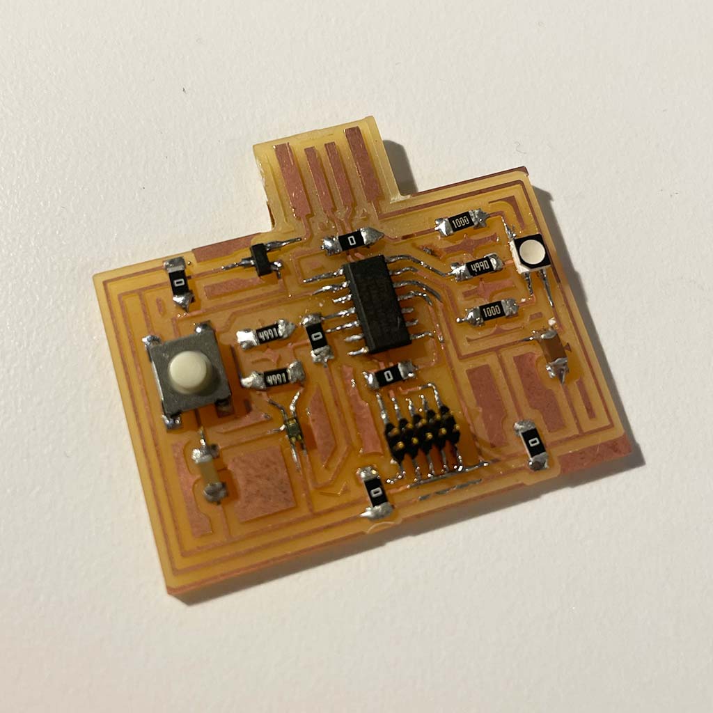
* Again, I could practice the soldering reflow. This time I made it by myself, and it also worked well:
Programming
1. Bootloading: The first step was to bootload the board. Since I kept using the same microcontroller (SAMD11C), I run the same code but used to CBA shop's computer to avoid potential issues with Mac M1.
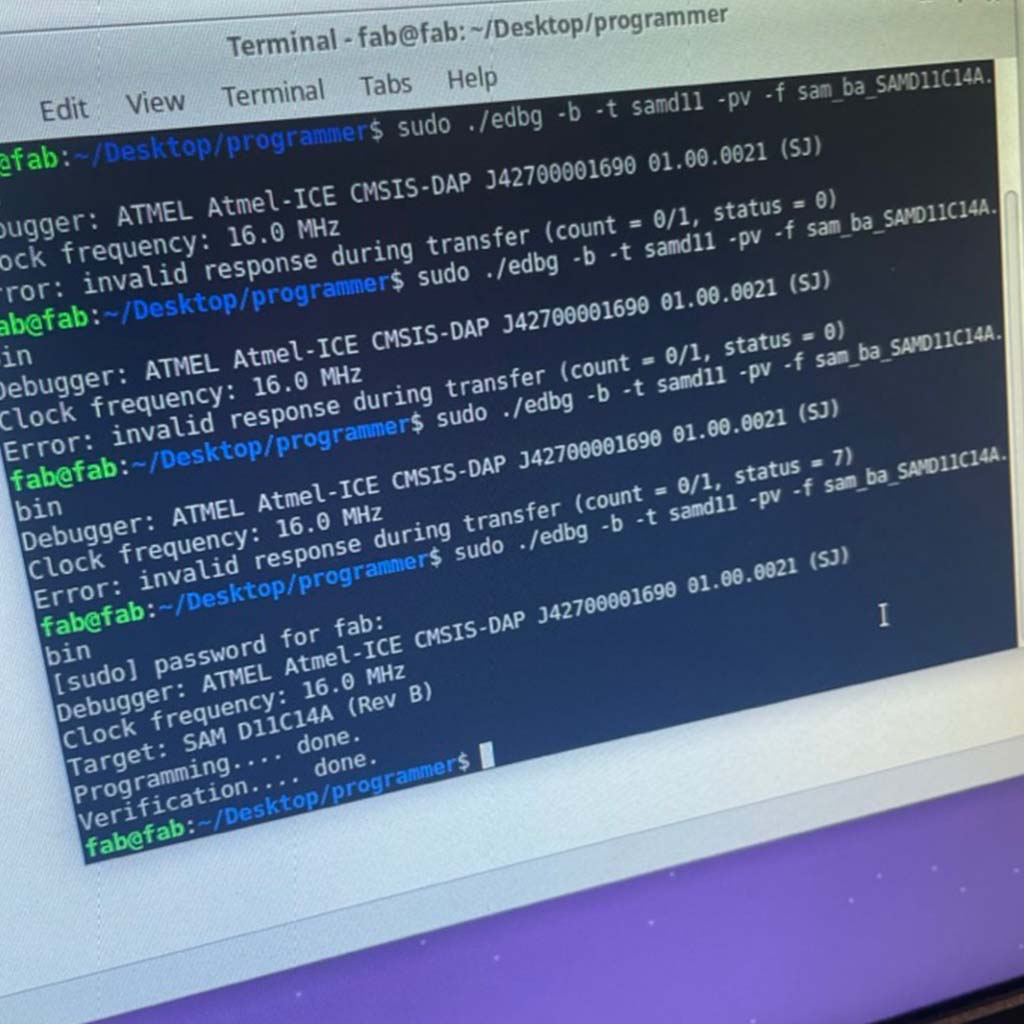
2. Programming in Arduino IDE: I used the same library and the same fab board file (Generic D11C14A). Also, I found this project from a previous year which used the same component and same microcontroller. I used as reference and updated the pins in order to work for my board.
Some learnings from working with Arduino IDE:
• Add the URL for your board/microcontroller (File > Preferences > Additional boards manager URLs). In this case: https://raw.githubusercontent.com/qbolsee/ArduinoCore-fab-sam/master/json/package_Fab_SAM_index.json
• Select the board and the port you are using. For my design, it was the Generic D11C14A.
• Keep the USB connection stable. In my case, I had to put some tape below my board to become more stable.
Finally, this was the code for the RGB LED. It basically varies the colors of the light based on a determined range of time.
Testing
After solving some issues with the USB port, I finally a board I created working as it should:
Backup Plan
To avoid the same issue that happened last week, I decided to have a backup plan since the beginning and bought a Adafruit board that could, at least, offer me some opportunities to learn how to deal with the embedded programming part.
Planning, Designing and Producing
Purchasing
For testing, I bought a Adafruit Proximit Trinkey.
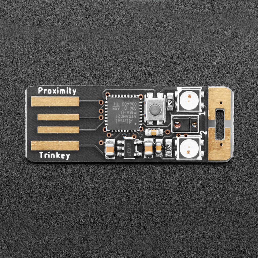
In addition to the ATMSAMD21The board includes:
1. The sensor APDS9960, which has a few different capabilities thanks to integrated IR LED, photodiodes, and RGB sensing.
• Proximity sensing up to about 6" away by bouncing IR light off an object.
• RGB color sensing can detect color when light refects off of an object - good for bright colorful items like LEGO bricks.
• Ambient light sensing - how dark or bright is it in the room?
• Basic gesture sensing using 4 cardinal locations of photodiodes - this sensor is a little tough to use but it does work with practice.
2. Two RGB NeoPixel LED
3. Two Capacitive Touchpads
4. Reset switch for starting your project code over or entering bootloader
Programming
The board comes with a demo that includes LED intensity changes based on proximity sensor input and LED color change based on the capacitive touchpads.
Since I made my original plan works, I didn't have much time to play with the Adafruit board. I was only able to reset it, change the demo and return to the shipped demo. In the next few days I plan to use it as a reference for my final project.
Files