07
EMBEDDED PROGRAMMING
This week we worked on embedded programming and getting our LED on the PCB to work.
| Tools: | Eagle, Roland SRM-20, Soldering Iron, Arduino, Atmel Programmer, Multimeter |
| Files: | Angler Traces, Angler Outline |
| Date: | 10.25.2022 |
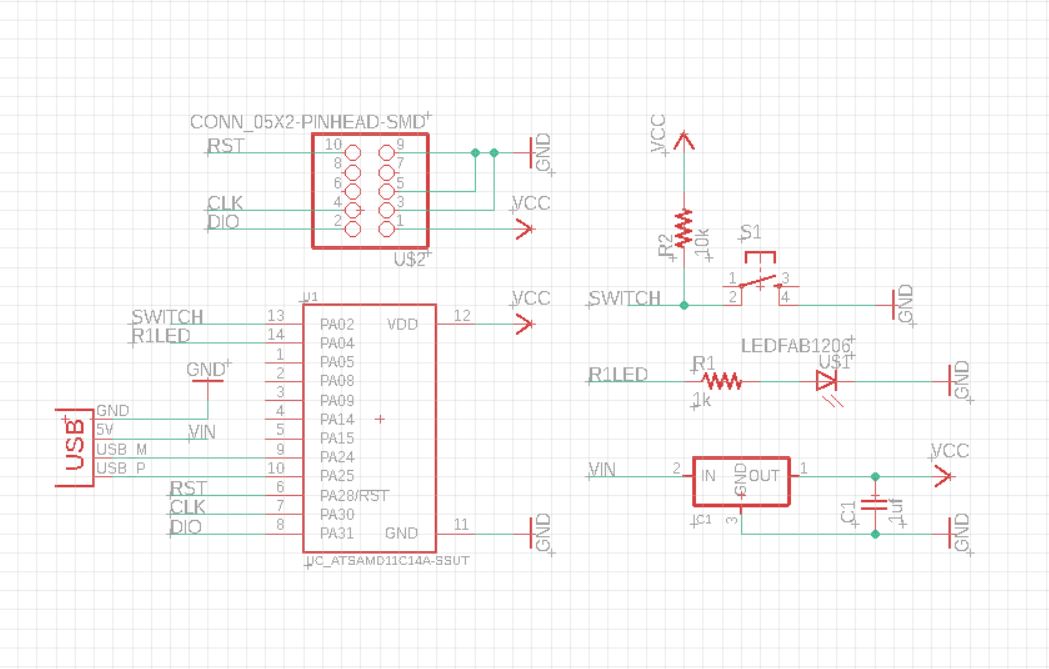
Schematic Design
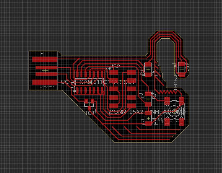
The assignment involved programming the board from Week 5 to do something, using the programmer made in Week 3. Since I had not been able to bootload my board from week 5 (because ATTiny44 is outdated), I went about making a new board with a switch and an LED. This time, I used an ATSAMD11C because of the abundance of support available in class for this model, as well as my success with the board from week 3 which used the same microcontroller. The USB connection also seems to be the preferred option. I modified the hello D11C echo board to include an LED, a switch, and a pull-up resistor. I used Eagle to draw the schematic of the board.
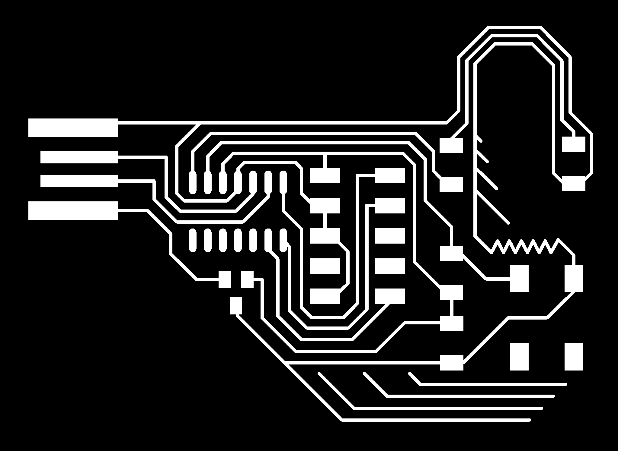
Board Design
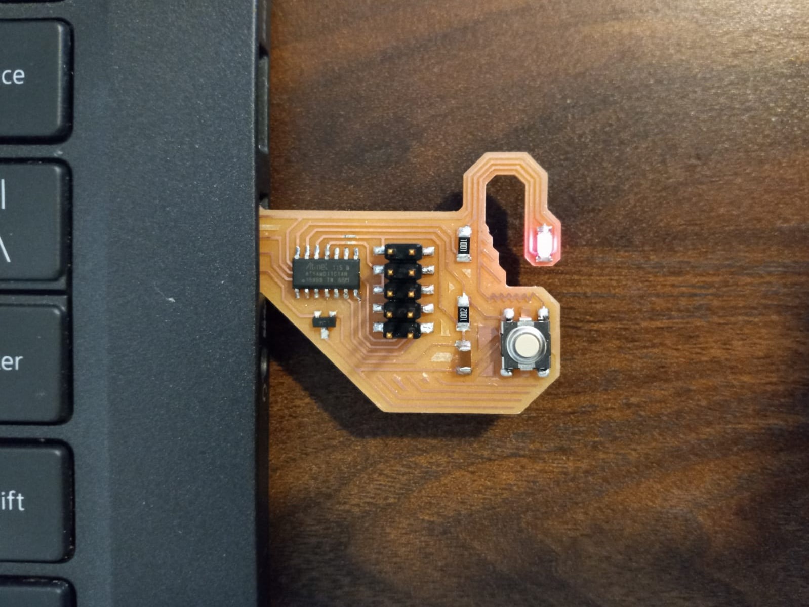
I wanted to make a PCB that looks like an anglerfish (inspiration: Finding Nemo). In the process, I referred to the original hello echo board to help untangling the components of the board. Routing the wires around the LED to be contained within the dangly bit proved tricky, but I figured it out without having to add any 0ohm resistors or jumper wires. Yet again, DRC (design rule check) was a very helpful command both in the checking for errors as well as to set the signal widths/clearances.

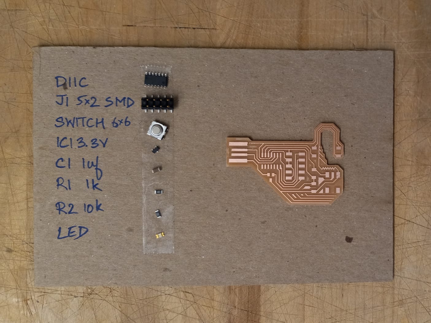
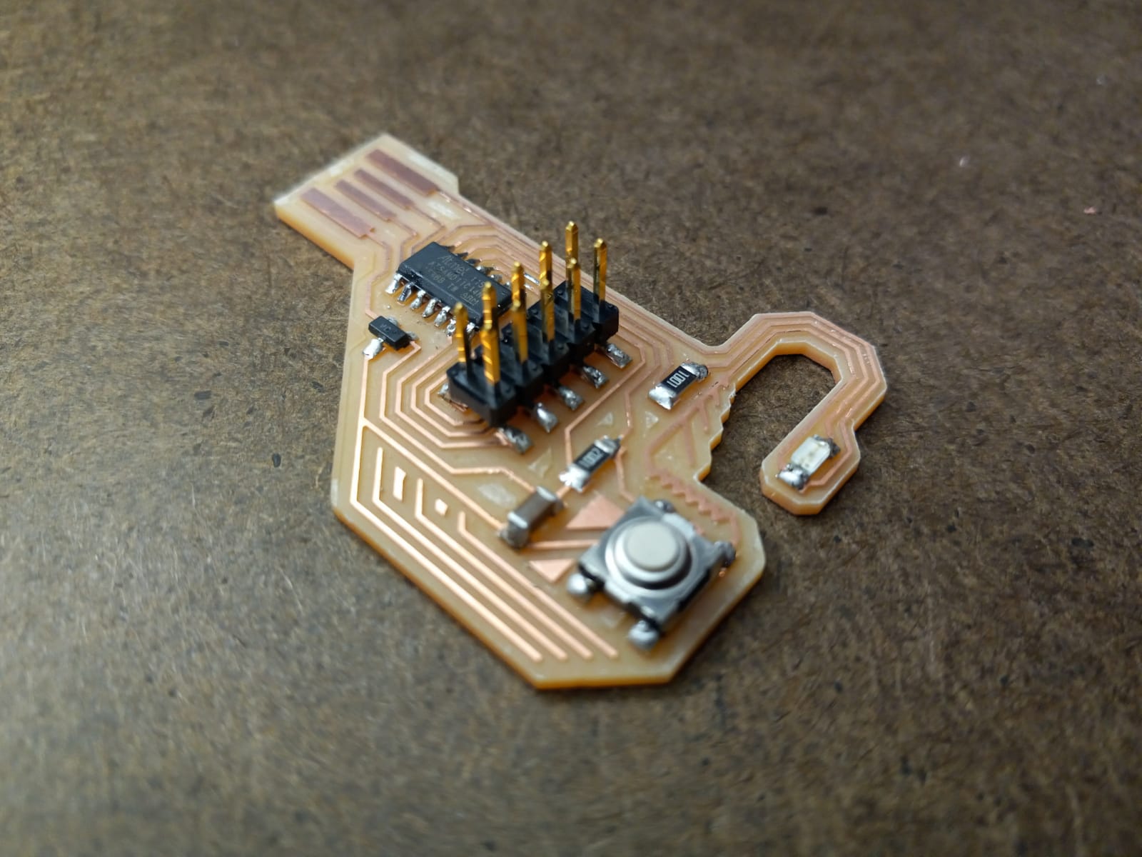
Milling and Stuffing
After processing the traces and outlines on Photoshop, I used Roland SRM-20 to mill the board. Mistake: While creating the final PNGs, I did not add margins outside the outline file. This resulted in the outlines lining up with the boundary of the PNG, so mods did not read all the outlines and the 1/32" endmill did not cut the board out completely. I tried using a band saw to cut the rest, but ended up cutting away a trace. I went back to Photoshop to fix margins and mill again before soldering and stuffing.
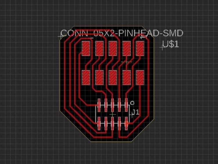
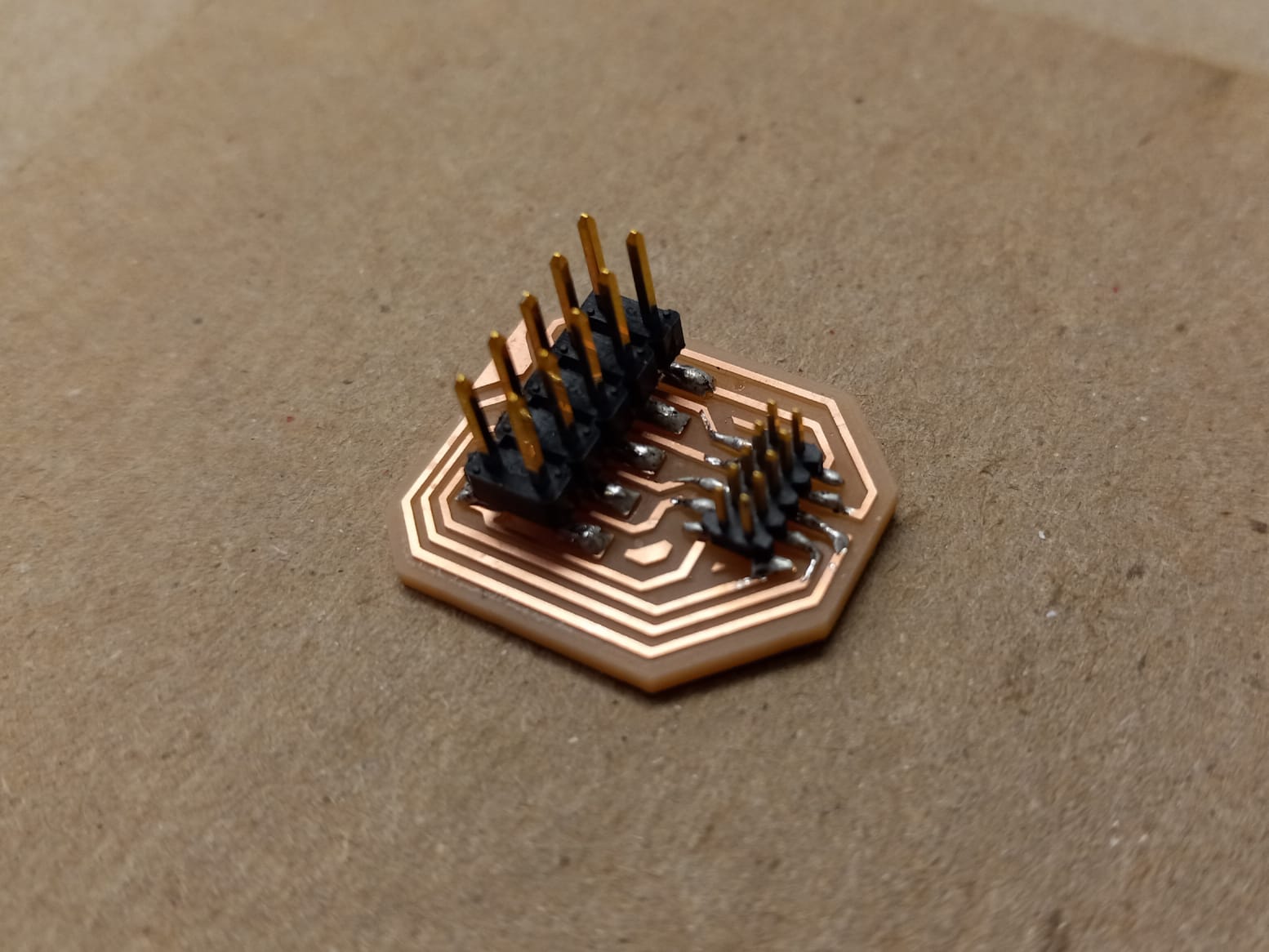
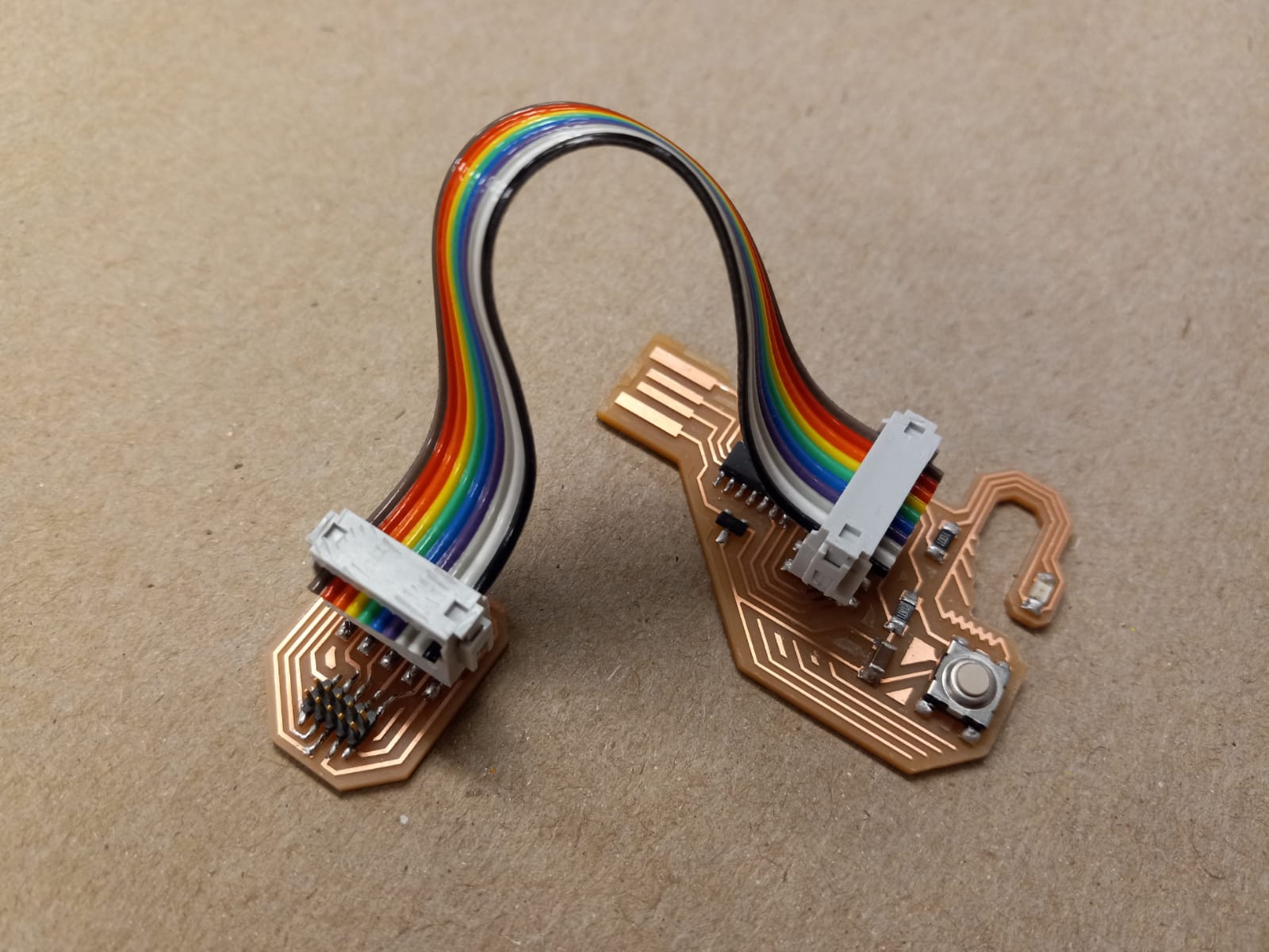
Making a Converter
Turns out the shop did not have the header for the larger 5x2 SMD connector, so I had to create another board for converting the larger 10 pin to a smaller one. This involved routing all the pins on the larger connector to the corresponding pins on the smaller one. They needed to match up exactly! After milling and stuffing the board, I used a multimeter to check the connections. The connecting cable (between the original board and the converting board) was made using a ribbon cable and a couple cable-to-board connectors. This was surprisingly easy!
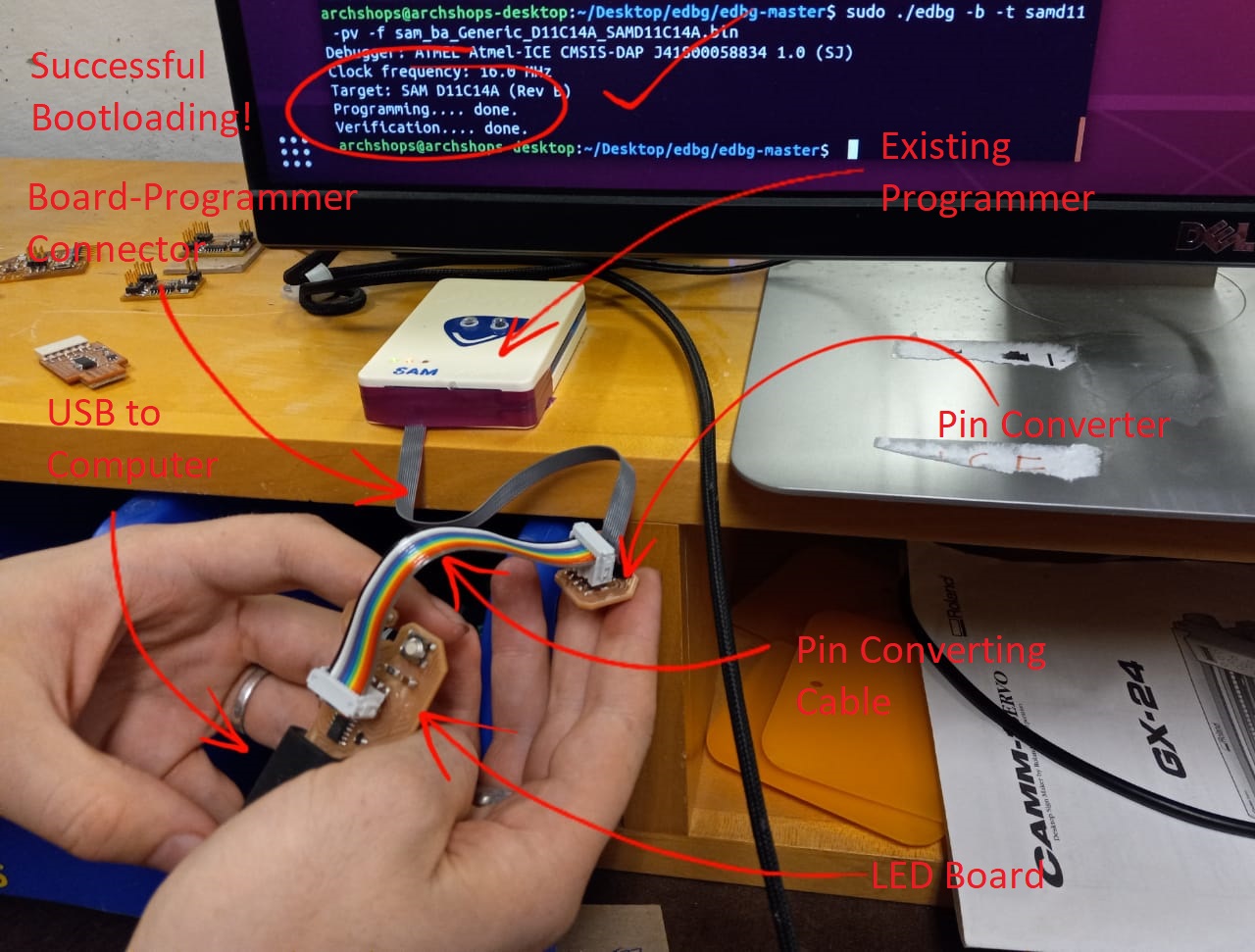
Bootloading
I successfully bootloaded my PCB using an existing programmer (although mine from also Week 3 works). edbg was already installed in the shop computer, so I just had to connect my PCB to the computer for power and to the Atmel programmer via the 10-pin JTAG converter. With the board connected and my terminal in the directory containing the bootloader bin file, I ran the following command:
sudo edbg -b -t samd11 -pv -f sam_ba_Generic_D11C14A_SAMD11C14A.bin
Programming
I installed Arduino IDE on my laptop using these instructions. Making sure the "Board" and the "Port" options are set correctly in the "Tools" menu, I proceeded to use the following to program my board.
            const int button = 2;
            const int led = 4;
            int ledflag = 0;

            void setup() {
              pinMode(button,INPUT);
              pinMode(led,OUTPUT);
              digitalWrite(led,LOW);
            }

            void loop() {
              if (digitalRead(button) == LOW) {
                if (ledflag == 0) {
                  ledflag = 1;
                  digitalWrite(led,HIGH);
                }
                else {
                  ledflag = 0;
                  digitalWrite(led,LOW);
                }
              delay(1000);
              }
            }