10
OUTPUT DEVICES
This week we worked on designing and making a board that controls an output device.
| Tools: | Eagle, SRM-20, Soldering Iron, Arduino IDE |
| Files: | Timer Traces, Timer Outline, Servo Traces, Servo Outline |
| Date: | 11.16.2022 (update: 12.16.22) |
Originally for this week, I programmed an OLED using my board from last week. Later, I also made a PCB for a servo motor for my final project.
Output Device 1: OLED
The board I made last week was an attempt to make a timer. It was designed to connect to an OLED to display time. A 2x2 header is connected to the I2C pins (SDA and SCL) on the SAMD21E17A microcontroller. The trials and tribulations of last week continued into this one. I encountered two additional issues while trying to get the OLED to work:
1. The traces connected to the 2x2 header meant for the OLED were ripping out again. I used super-glue to fix the header traces to the board. When the multimeter was still not indicating a connection, I tried soldering weak areas around the header, but the solder wasn't staying on the board. Maybe the glue made a layer that the iron wasn not effectively able to surpass. I had to solder a wire to bridge the potential gap. This worked, so I tried to preserve the connections by coating the area with superglue.
2. I used example code from the Adafruit SSD1306 library to test the OLED. It worked but everytime I unplugged and replugged it through the USB, I had to push the code to the board again. Anthony suggested this may be because of some issue having to do with the reset pin, so I was playing around with the two lines of the code that mentioned "OLED_RESET". This issue was resolved when I changed the reset pin from "-1" to "0".
For the final project, I coded the OLED to serve as an output screen that gives the user feedback. One main functionality was a timer (see final project for details).
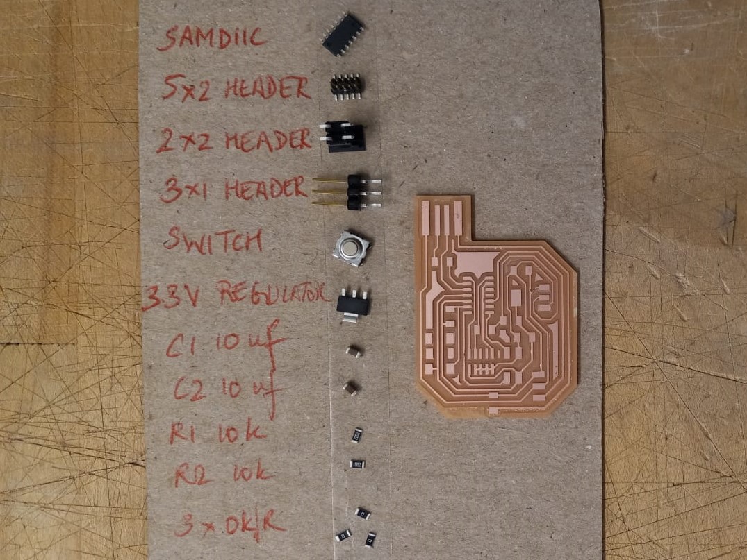
Output Device 2: Servo Motor
After the machine-building week, I felt more confident with motors and wanted to use one for my final project. I designed and made a PCB that has a servo, serial communitcation pins to talk to the above board's OLED, and a switch as a back-up input device.
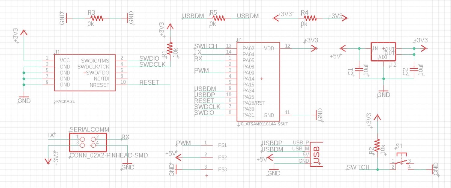
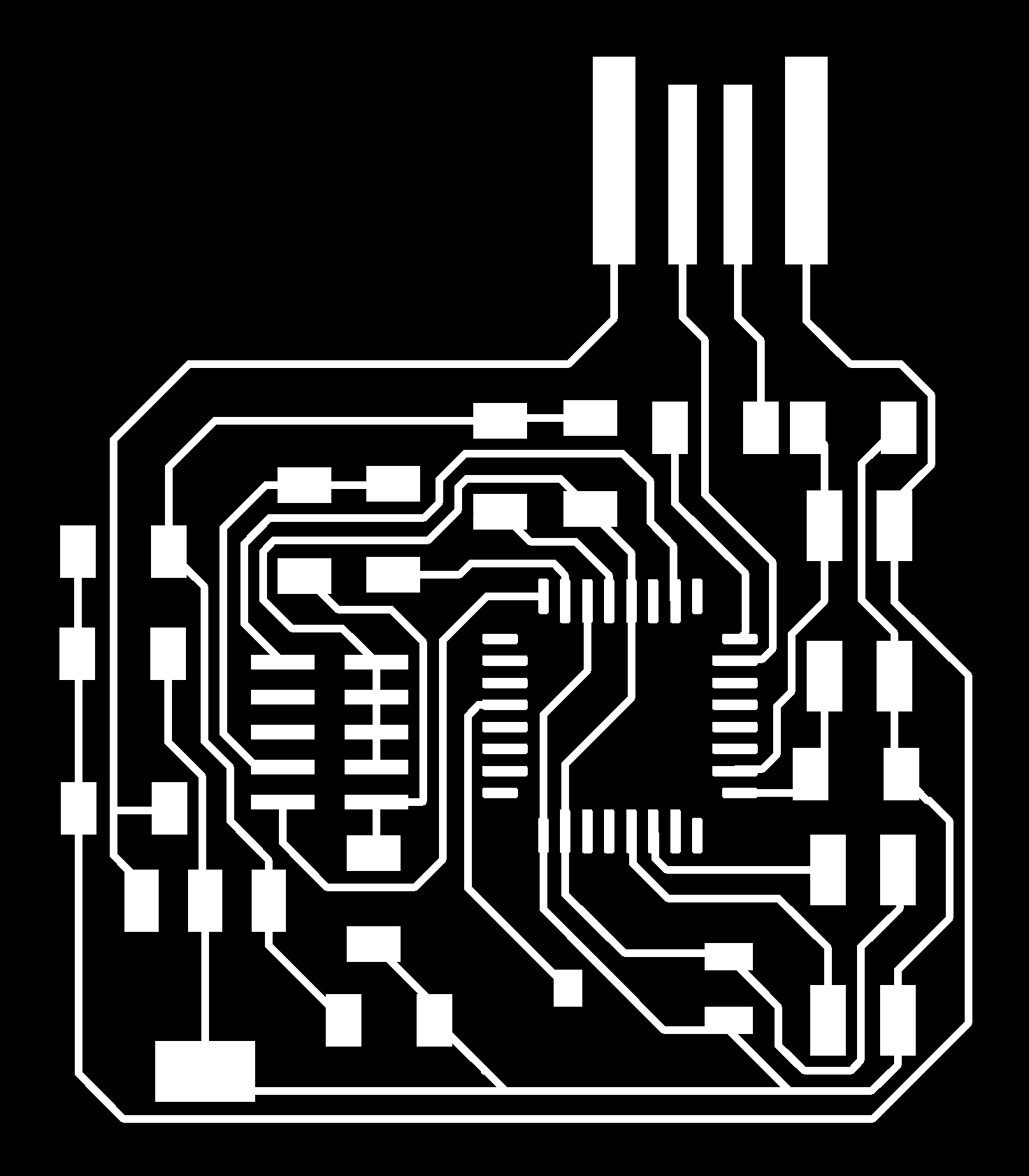
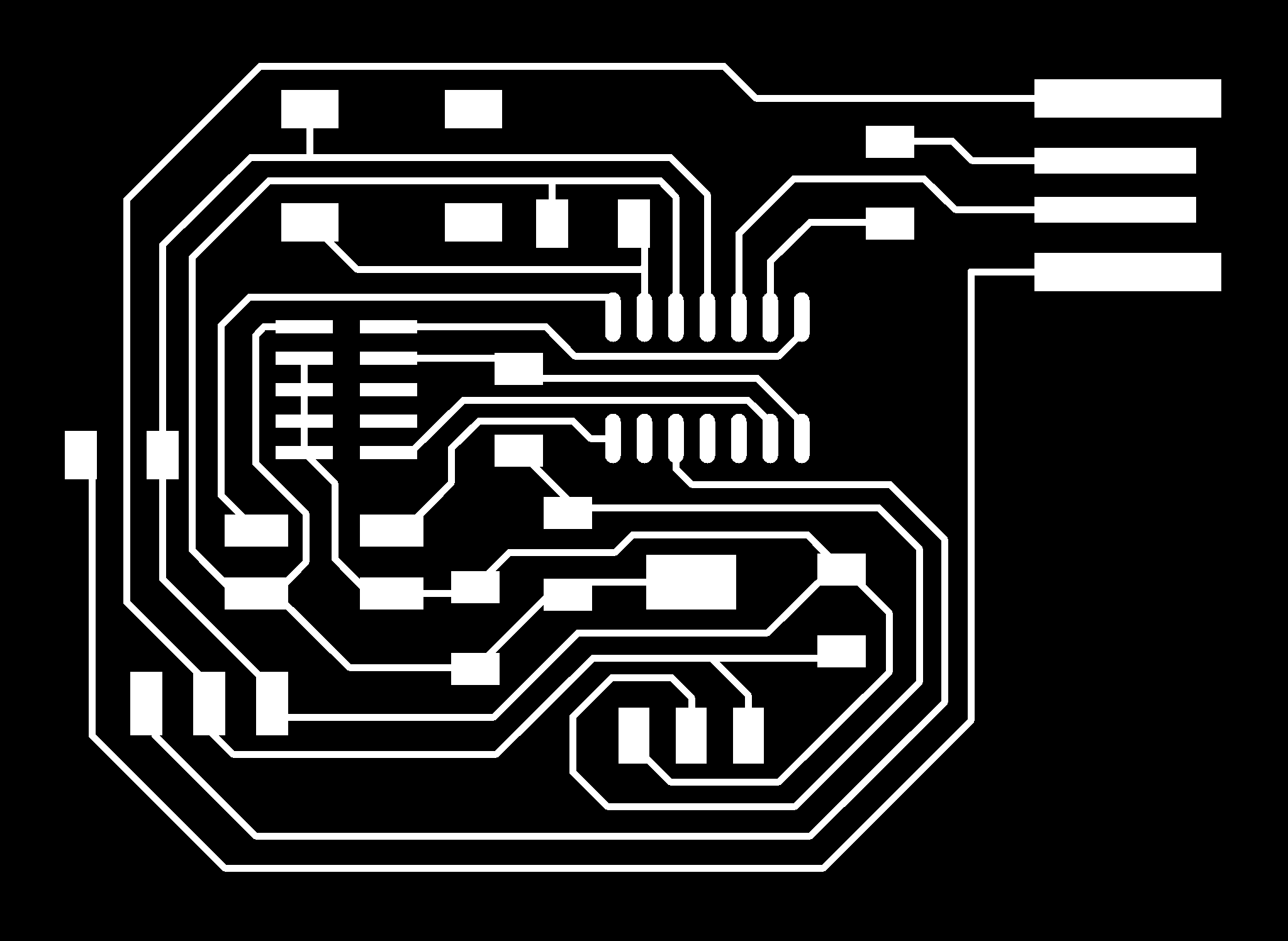
Board
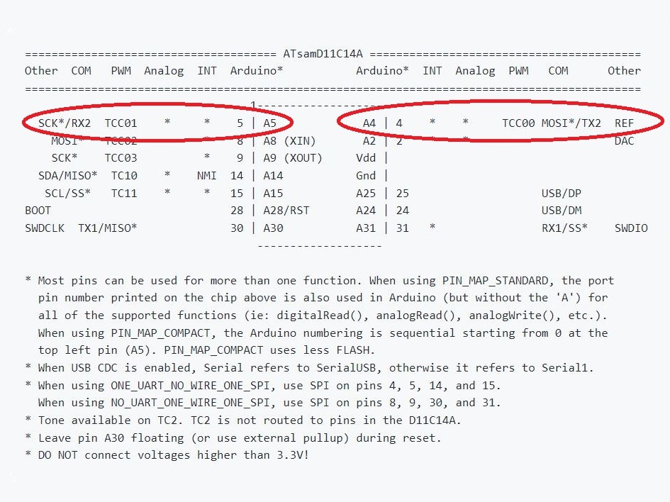
Schematic: I used a SAMD11 for this board because of my previous issues with the SAMD21. I used the TX2 and RX2 pins for the serial communication header. The fab library for Eagle did not have a footprint for the servo, so Anthony helped my edit the 1x6 FTDI-SMD-HEADER to remove 3 of it's pads. One other consideration was that the servo, unlike other parts I've used thus far, needs 5V for functioning.
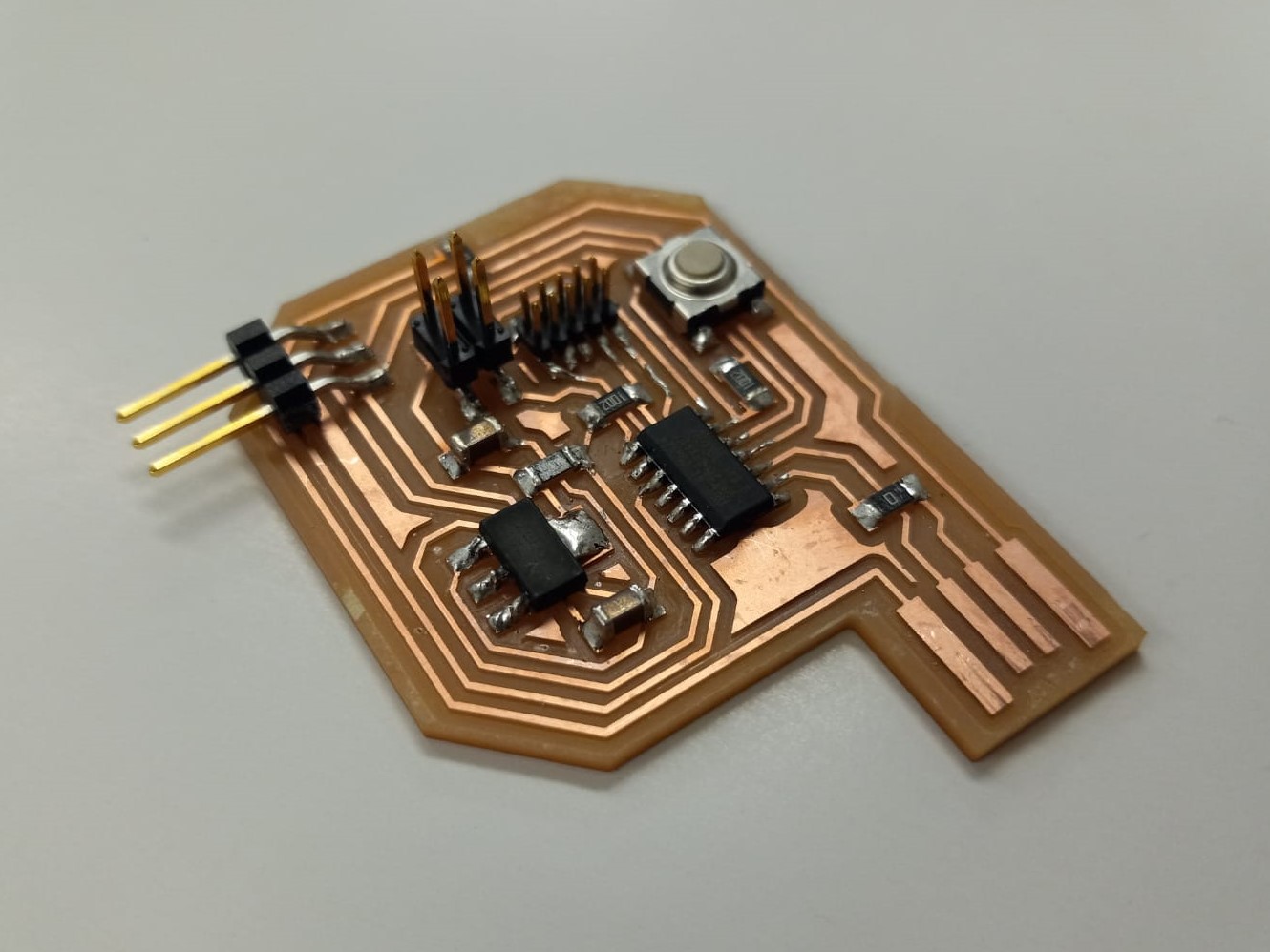
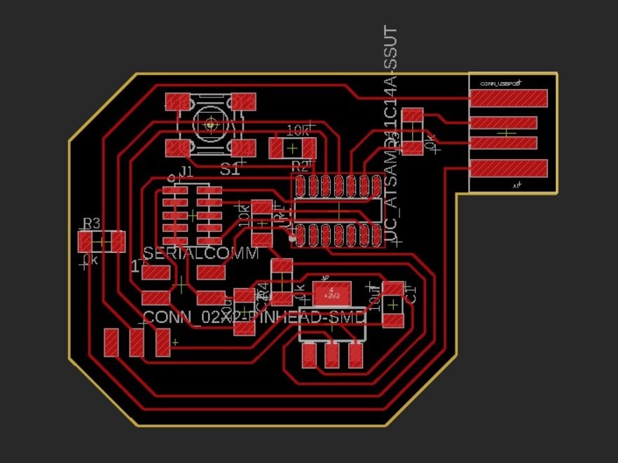
Design: This time I was mindful of leaving enough room around the traces to allow enough room for soldering. And also maybe keep the traces from thinning out because of crowding--my theory about why the board from week 9 had thinner traces despite same design rules. Additionally, the pads for the servo needed to be near the perimeter of the board because of the way the pins are oriented horizontally.
Bootloading: Apparently, I placed the programming header too close to a 2x2 header, such that it was hard to physically connect it to the Atmel-ICE. I had to shave off the sides of the female header of the bootloader to make the connection possible.
Programming
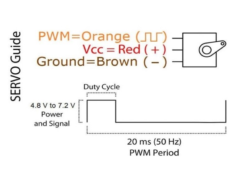
I used fabacademy code here to code the servo's PWM (pulse-width modulation) signal. For the final project, I modified this code to set the appropriate angle and speed for the motor (see final project).
  int servo = 9;
  int angle;
  int pwm;

  void setup(){
  pinMode(servo, OUTPUT);
  }

  void loop (){
  for (angle = 0; angle <= 140; angle += 5)  {
    servoPulse(servo, angle);  }
  for (angle = 140; angle >= 0; angle -= 5)  {
    servoPulse(servo, angle);  }
  }

  void servoPulse (int servo, int angle){
  pwm = (angle*11) + 500;      // Convert angle to microseconds
  digitalWrite(servo, HIGH);
  delayMicroseconds(pwm);
  digitalWrite(servo, LOW);
  delay(50);                   // Refresh cycle of servo
  }