Last week for input week I planned out a tic-tac-toe board, but met with challenges. This week, I took what I learned and successfully created two working boards.
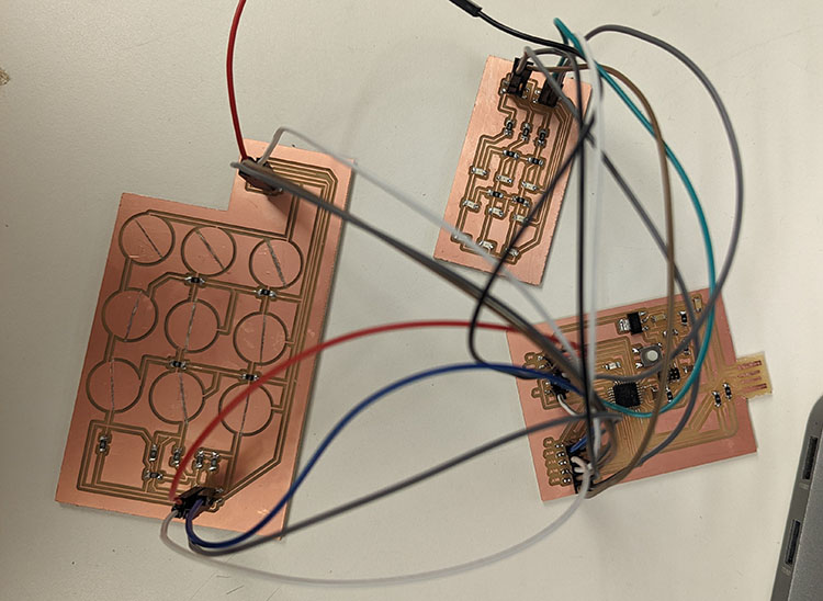
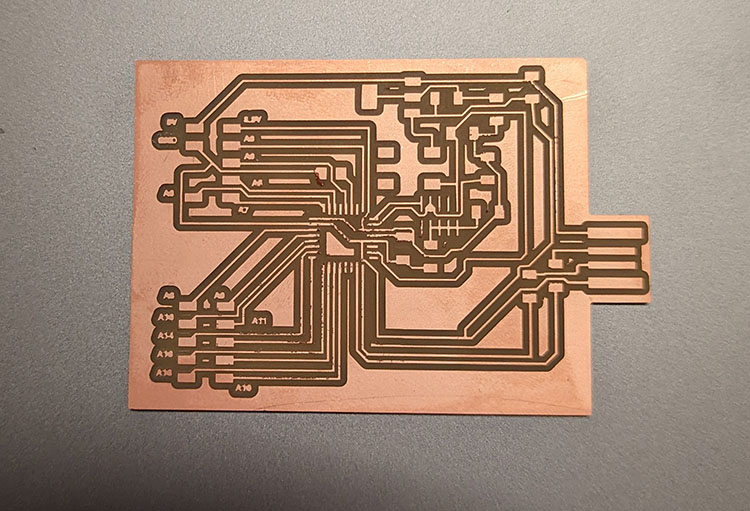
I designed and milled three boards this week:
- Download: A capacitive touch grid (left)
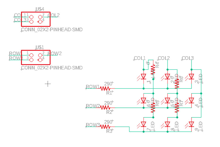
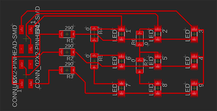
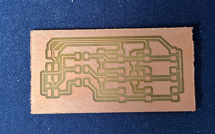
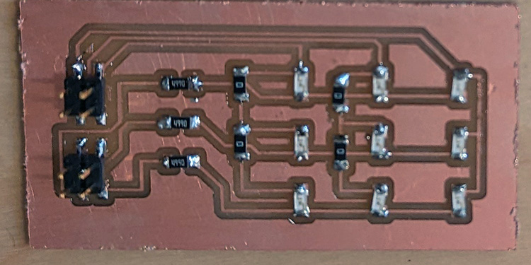
- Download: An LED multiplexed grid (middle)
- A general use dev-board (right)
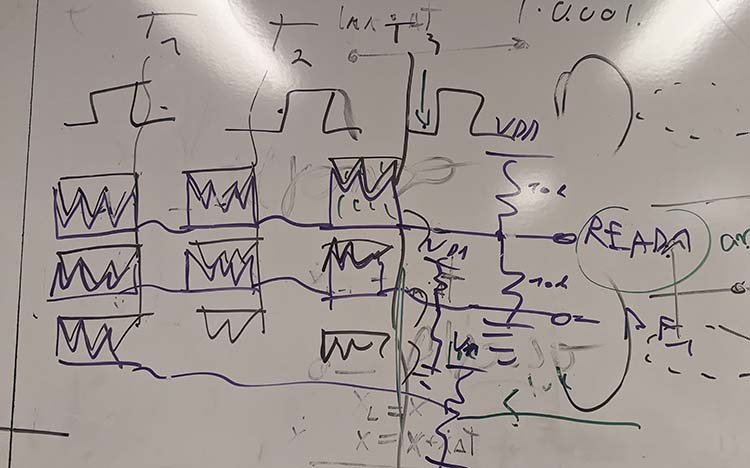
Below is the code for the capactive touch grid to turn on individual LEDs. The touch grid is based on code originally written by Robert Hart and found in the class documentation.
#include <avdweb_AnalogReadFast.h>


// code for touch grid based on a program by Robert Hart Mar 2019


#define PIN_TX1 14

#define PIN_TX2 15

#define PIN_TX3 16


#define PIN_RX1 8

#define PIN_RX2 10

#define PIN_RX3 9


#define PIN_COL1 3

#define PIN_COL2 5

#define PIN_COL3 6


#define PIN_ROW1 17

#define PIN_ROW2 18

#define PIN_ROW3 19


long result;   //variable for the result of the tx_rx measurement.


void setup() {


    Serial.begin(9600);


    //col

    pinMode(PIN_COL1, OUTPUT);

    pinMode(PIN_COL2, OUTPUT);

    pinMode(PIN_COL3, OUTPUT);


    //row

    pinMode(PIN_ROW1, OUTPUT);

    pinMode(PIN_ROW2, OUTPUT);

    pinMode(PIN_ROW3, OUTPUT);


}


long tx_rx(int t, int r){         //Function to execute rx_tx algorithm and return a value


    pinMode(t, OUTPUT);

    int read_high;

    int read_low;

    int diff;

    long int sum;

    int N_samples = 100;    //Number of samples to take.  Larger number slows it down, but reduces scatter.


    sum = 0;


    for (int i = 0; i < N_samples; i++) {

         digitalWrite(t,HIGH);              //Step the voltage high on conductor 1.

         read_high = analogReadFast(r);        //Measure response of conductor 2.

         delayMicroseconds(100);            //Delay to reach steady state.

         digitalWrite(t,LOW);               //Step the voltage to zero on conductor 1.

         read_low = analogReadFast(r);         //Measure response of conductor 2.

         diff = read_high - read_low;       //desired answer is the difference between high and low.

         sum += diff;                       //Sums up N_samples of these measurements.

    }


    pinMode(t, INPUT);


    return sum;

}                         //End of tx_rx function.


void ledsOff(){

    digitalWrite(PIN_COL1, LOW);

    digitalWrite(PIN_COL2, LOW);

    digitalWrite(PIN_COL3, LOW);


    digitalWrite(PIN_ROW1, LOW);

    digitalWrite(PIN_ROW2, LOW);

    digitalWrite(PIN_ROW3, LOW);

}


void loop() {


    long one = tx_rx(PIN_TX1, PIN_RX1);


    if (one > 10000) {

        ledsOff();

        digitalWrite(PIN_COL1, HIGH);

        digitalWrite(PIN_ROW2, HIGH);

        digitalWrite(PIN_ROW3, HIGH);

    }


    long two = tx_rx(PIN_TX2, PIN_RX1);


    if (two > 10000) {

        ledsOff();

        digitalWrite(PIN_COL2, HIGH);

        digitalWrite(PIN_ROW2, HIGH);

        digitalWrite(PIN_ROW3, HIGH);

    }


    long three = tx_rx(PIN_TX3, PIN_RX1);

    if (three > 10000) {

        ledsOff();

        digitalWrite(PIN_COL3, HIGH);

        digitalWrite(PIN_ROW2, HIGH);

        digitalWrite(PIN_ROW3, HIGH);

    }


    long four = tx_rx(PIN_TX1, PIN_RX2);

    if (four > 10000) {

        ledsOff();

        digitalWrite(PIN_COL1, HIGH);

        digitalWrite(PIN_ROW1, HIGH);

        digitalWrite(PIN_ROW3, HIGH);

    }


    long five = tx_rx(PIN_TX2, PIN_RX2);

    if (five > 10000) {

        ledsOff();

        digitalWrite(PIN_COL2, HIGH);

        digitalWrite(PIN_ROW1, HIGH);

        digitalWrite(PIN_ROW3, HIGH);

    }


    long six = tx_rx(PIN_TX3, PIN_RX2);

    if (six > 10000) {

        ledsOff();

        digitalWrite(PIN_COL3, HIGH);

        digitalWrite(PIN_ROW1, HIGH);

        digitalWrite(PIN_ROW3, HIGH);

    }


    long seven = tx_rx(PIN_TX1, PIN_RX3);

    if (seven > 10000) {

        ledsOff();

        digitalWrite(PIN_COL1, HIGH);

        digitalWrite(PIN_ROW1, HIGH);

        digitalWrite(PIN_ROW2, HIGH);

    }


    long eight = tx_rx(PIN_TX2, PIN_RX3);

    if (eight > 10000) {

        ledsOff();

        digitalWrite(PIN_COL2, HIGH);

        digitalWrite(PIN_ROW1, HIGH);

        digitalWrite(PIN_ROW2, HIGH);

    }


    long nine = tx_rx(PIN_TX3, PIN_RX3);

    if (nine > 10000) {

        ledsOff();

        digitalWrite(PIN_COL3, HIGH);

        digitalWrite(PIN_ROW1, HIGH);

        digitalWrite(PIN_ROW2, HIGH);

    }


}
Plans for Next Week
The plan since input week has been to make a video game board (that can play tic tac toe, and hopefully other games). The first step will be to update the LED grid with RGB LEDs. Since each LED will need 4 connectors instead of 2, I'll need 12 pins for my LED grid alone. This, plus the pins for my touch grid, are more than I have available on my dev board, so my first "Networking week" step will be to design a new board with two chips that can work together to control the external boards.
As far as code changes, I'll have to refine my multiplex LED code as my LED code currently doesn't work as intended when multiple LEDs turn on.
I also want to use networking week to build a prototype for my final project, where I use Bluetooth (maybe, we'll see what the recs are in this week's lecture) to activate one device from another when a button is pressed.
Capacitive Touch Grid
The design for the grid was initially Quentin's, put together at around 11pm after a number of failed experiments with the built-in X-Y touch sensors on the SMD21 last week.
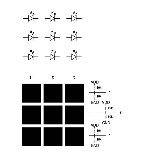
The design included a custom componenet I created for the touch pads. The left pin-outs connect to the transmitter pins and Ground, the right pin-outs connect to the Reader pins and VDD.
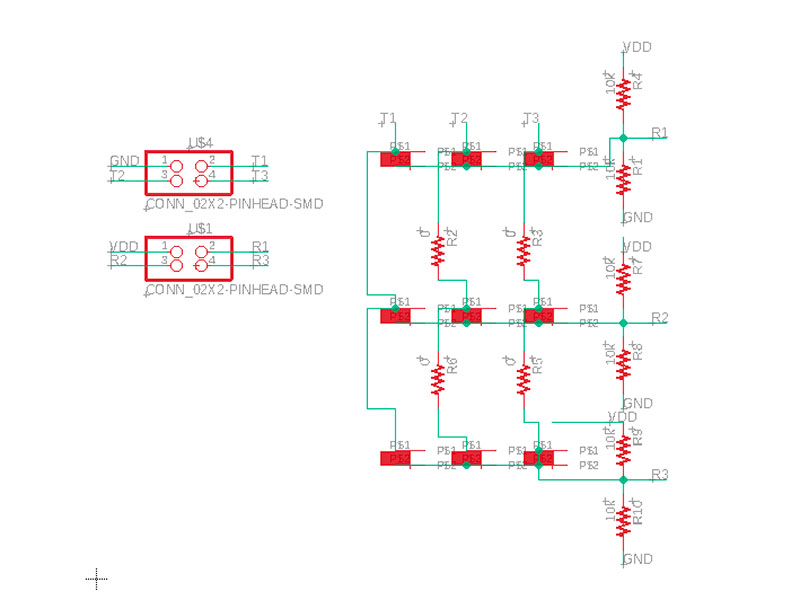
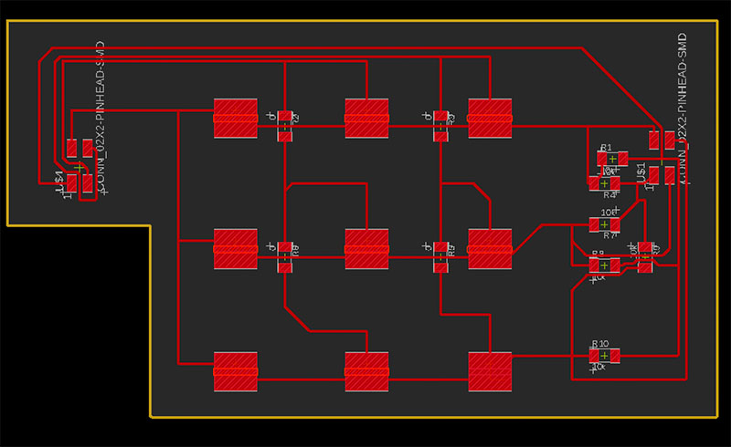
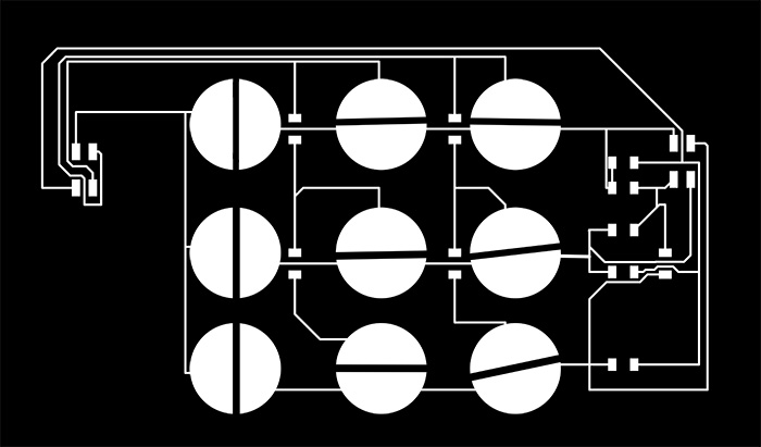
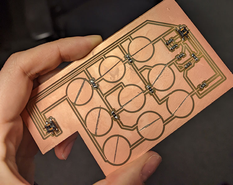
I actually didn't include the cuts between the pads in my first pass, and cut them out with an x-acto afterwards.
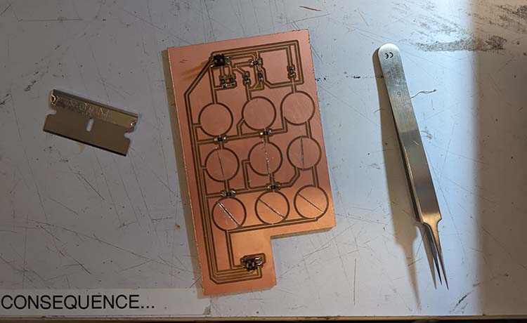
Whoops
LED Grid with Multiplexing
I found this great YouTube tutorial to understand multiplexing better. Essentially, by connecting 'row' and 'column' pins to act as Ground and Power, you can control an entire grid of LEDs.
Dev Board
Before this week, if I ever wanted to test something without a standalone board I would try it out first on the Adafruit Arduino Trinket M0 board (which also uses the SMD21 chip). This week, pushed by a lack of pins on the Adafruit board, I designed my own!
While my ultimate goal next week is to build a two-sided standalone game board, this test board and breakout boards allowed me to do individual tests before combining all the elements.
I had some issues programming the board initially. Continuity tests (and help from Dave and Atmel Studio) revealed that my two USB traces were connected with a small artifact from milling. I separated them with an x-acto, and the board worked!
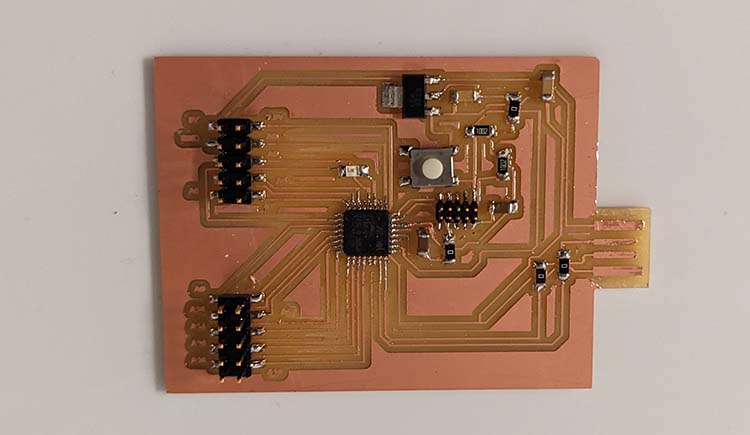
First test - built-in LED working :)
Ordering PCBs
In addition to the output week assignments, I also ordered my first PCB this week!
My final project is going to be a wearable (a mask), which makes the size of my electronic components important.
I spent the first part of the week redesigning my board from Embedded Programming week to be as small as possible.
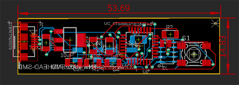
Main PCB
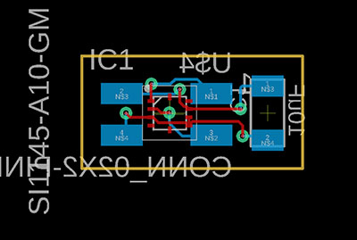
Light sensor
The boards were ordered from PCBWay. I prepared the files in the "Manufacturing" Tab of Fusion. First, I prepared everything with "CAM Processor" (the selection is in the top bar of the Manufacturing tab) and then exported the bundled .zip file to upload with "Export Gerber etc".
I had to wait about an hour for my uploads to be approved. After that, ordering was easy, and about $1/board.