Week 1 - Computer-controlled Cutting
This weeks individual assignment was two-fold: lasercut a paramatric construction kit and vinyl cut something. The group assignment concerned characterizing the lasercutter in terms of kerf, joint clearance and types, focus, power, and speed. Details on the group assignment can be found here.
Lasercutting Assignement
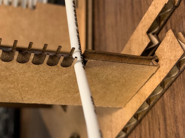
For the lasercutting assignment, I decided to create a bobbin for an air-core high-frequency power transformer. The below transformer was constructed using wood stock, a handsaw, and a drill; a very time consuming process, especially when considering creating templates and proper alignment. For a smaller transformer (half the diameter), a cardboard construction could be useful and save a lot of time. The construction, however, needs to be relatively sturdy to counteract bending forces in the solid copper, so double layers may be necessary in some cases.
We start by generating a parameter list, including the transformer design parameters as well as the bobbin constructin parameters, variable joint thickenesses, kerf, etc. This all goes into an XML file to be read by Autodesk Inventor, which will then update each part. There are three coils in this transformer design, each individually defined by several parameter: number of turns, center to center coil diameter, copper conductor diameter, conductor with insulation diameter, and pitch. The relative axial positions of the coils is defined with two additional spacing variables. Other variables that define the structure are: joint thickness (for snap joints), joint over hang (for locking snap joints), cardboard thickness, number of vertical support posts, radial thickness of the vertical support posts, and the axial spacing clearance for each vertical support posts. The joint values along with the kerf were determined through the group assignment this week.
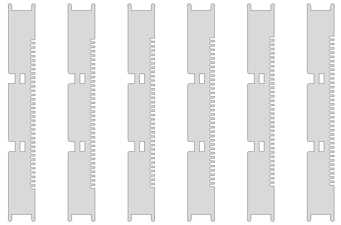
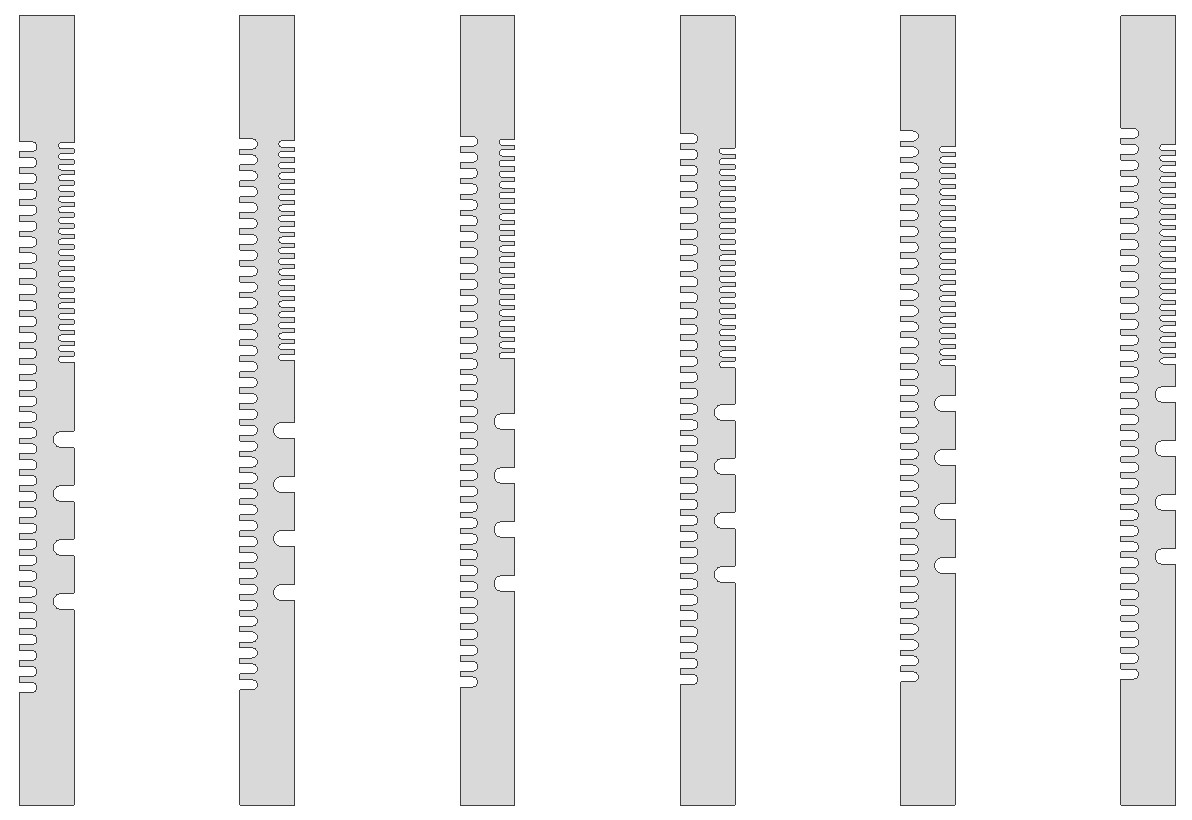
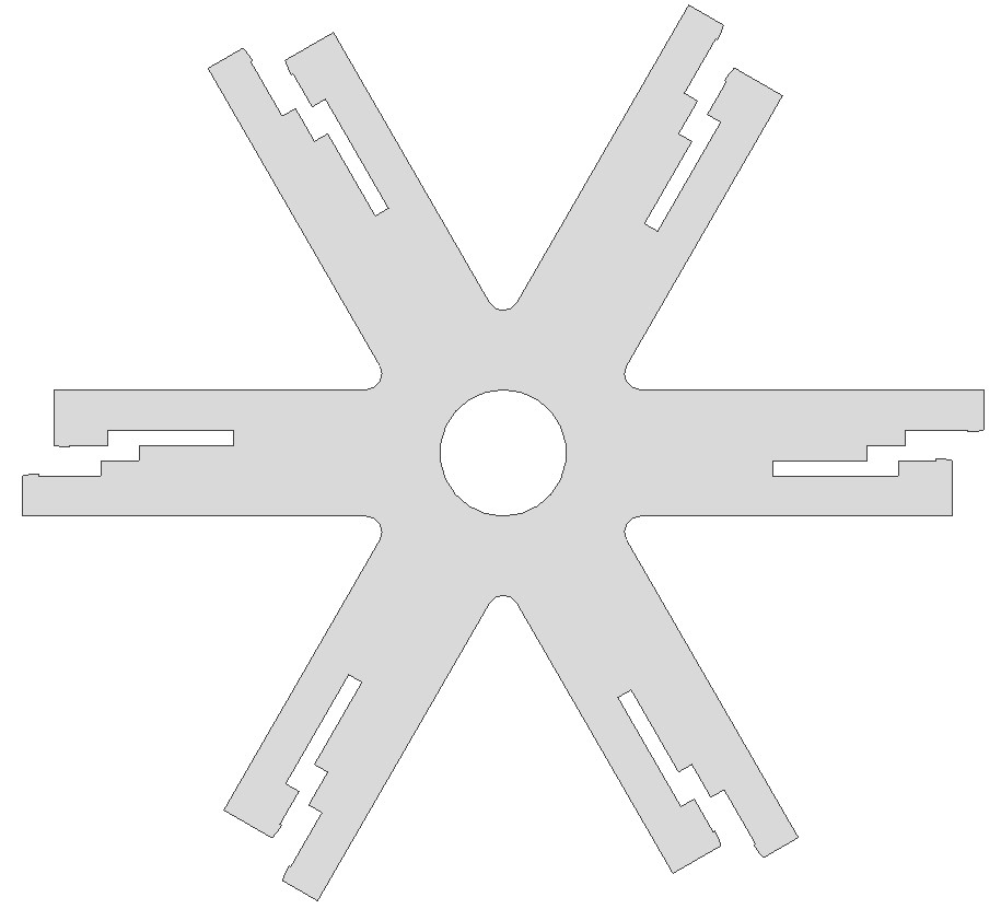
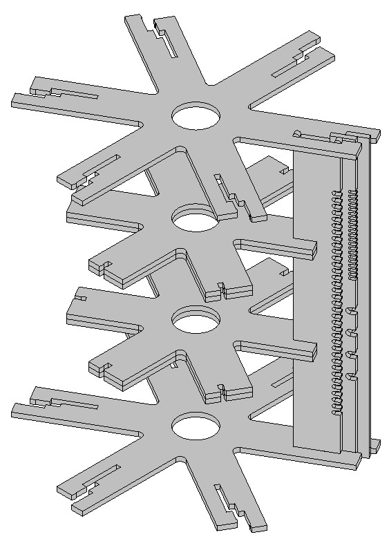
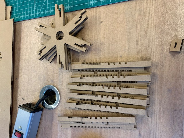
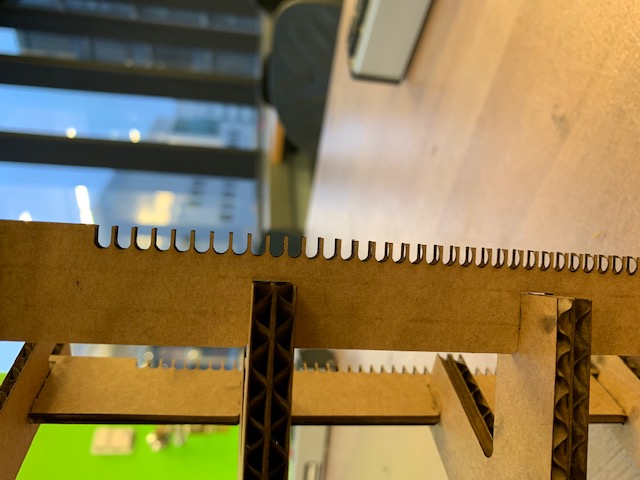
When I tried to directly sketch a .dwg file, Inventor didn't like me using the parameters from the XML in the part dimensions. So instead, I decided to just create 3D parts, which is fine because it will let me check geometry through assembly. I decided to go with an inner, middle, and outer vertical support posts. These are "comb-like" structures in which the coils are wound into. Each support's slots should be vertically offset according to the fraction of the pitch spanned by the angle between posts. This is due to the geometry of the helically-wound coils. The posts (for a count of six) are shown below in order: inner, middle, outer.
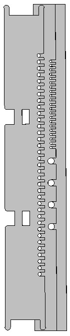
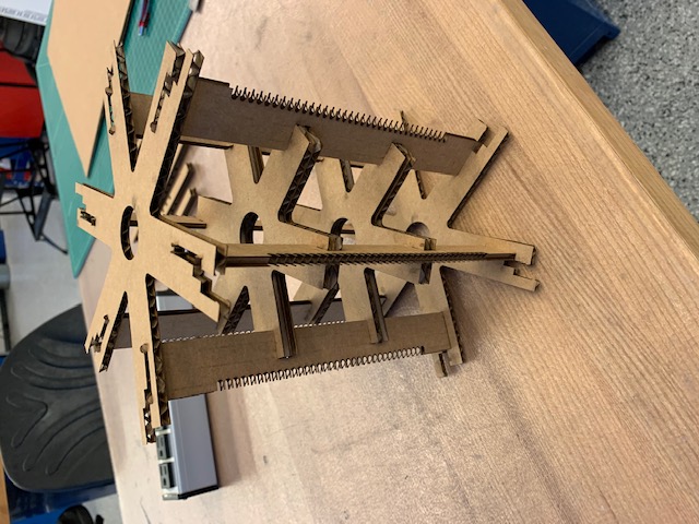
When assembled together the intersection of the three radial posts that make up a single vertical support looks like the following.
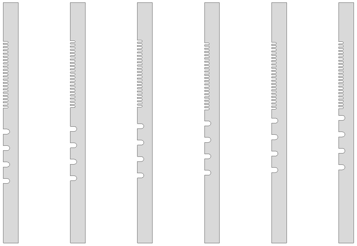
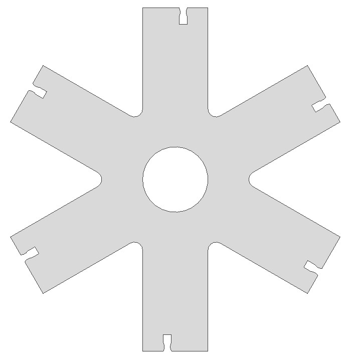
The top and bottom of the posts are held by identical spreaders, which locate the post to the proper radius and vertical alignment. There are also double-layer middle spreaders which help suppor the inner posts and give the bobbin structure. The two spreader geometries are shown below in order: top then middle.
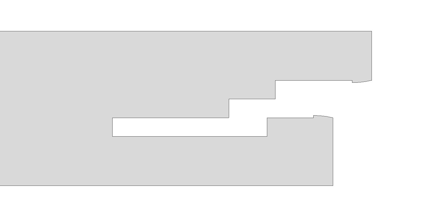
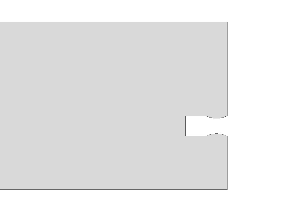
The inner post are first snap-fit into the middle spreader and the top and bottom spreaders may be snap fit onto the inner post. After winding the inner coil onto the inner posts, the middle post is slid into the top and bottom spreaders, locked into radial position by a joint on the top spreader and locked into axial position by the inner coil turns. The two outer coils may then be wound onto the middle post and finally the outer posts are snapped into the top spreader in a similar fashion to the middle post.
When including kerf in the design of each part, a good rule of thumb is to add 2 times the kerf radius to the dimension of the part if the dimension describes something that will be in the end part, and subtract 2 times the kerf radius from the dimension if the dimension describes something that will be cut out of the part. For example, when creating a square with a circle cut out, the square dimensions should have two times the kerf radius added to them and the circle diameter should be subtracted by two times the kerf radius. Accounting for kerf is even trickier when working with features that must be located properly in an absolute sense rather than just relatively. This is the case in the bobbin, in which the all of the lasercut cardboard supports must be made such that, when assembled, the coil slot cut-outs are the proper absolute diameter from the center. For some parts in the assembly, the kerf is inconsequential.
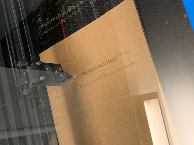
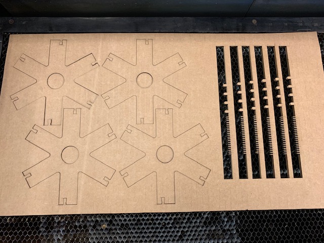
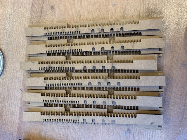
Each part model is imported to a .dwg in Inventor, in order to get the top view sketch, and the .dwg is exported as a PDF. These PDFs are ported over to the computer connected to the laser cutter using a USB drive. Each PDF is individually opened up in Corel and the software converts the PDF to curves. I highlight all of the curves and set the color to red and thickness to hairline. In the print preferences, I set the color red to be a vector cut with 95% power and 16% speed. This is what I found to be most effective in almost always cutting fully through the cardboard. The z-axis was calibrated for proper focus to the best of my ability (there was always some bow in the cardboard) everytime I used a new sheet of cardboard. The parts were all cut out, laid out, and then assembled without the middle or outer posts.
Vinyl-cutting Assignement
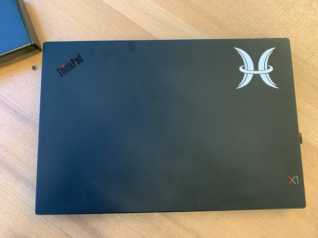
The vinyl cutting assignment was fairly straight-forward. I decided to cut the logo of the company that I work for in white vinyl and stick it onto my laptop. Turning the logo into a black-only PNG to be read by mods was the hardest part of the assignment. To do this, I first opened up a JPG of the logo in GIMP and, using the "fuzzy select tool," clicked on the white background (I have to work with the negative of the image because of gradients in the logo that the fuzzy select tool doesn't like).
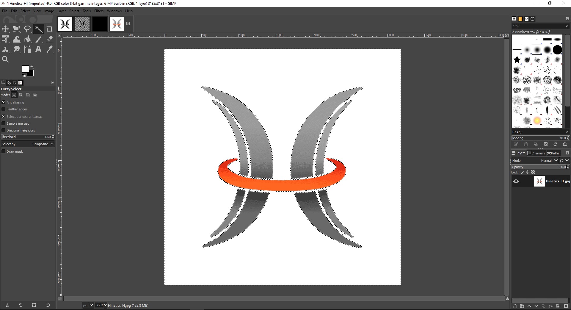
This detects and selects the boundaries of the image. I then create a new layer and use the bucket fill tool to fill the background with white. This layer, however, now has a transparent spot where the logo should be.
I can now delete the layer with the original image and create a new layer, moved it below the white/transparent layer, deselect the logo using "ctrl+shift+A," and paint the new layer black.
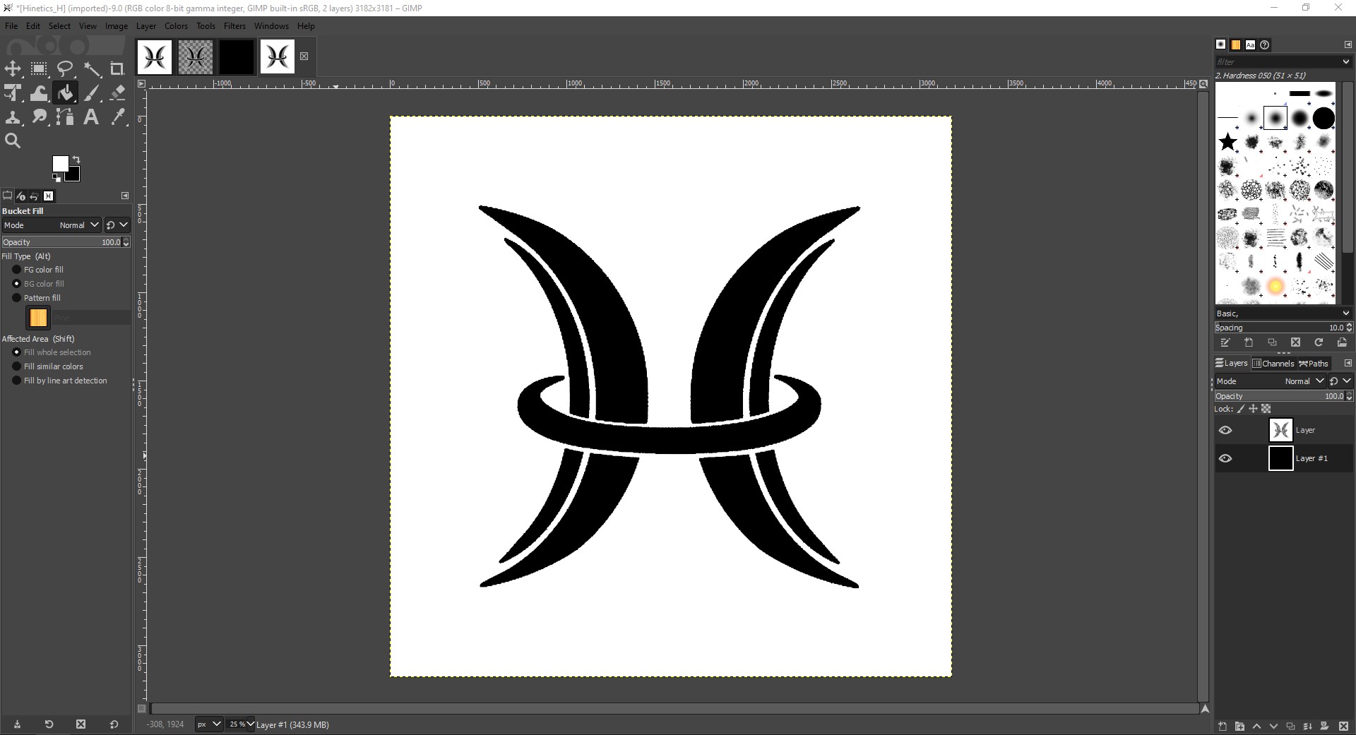
Now, to make the white background transparent, I merge the top layer down such that resulting layer is just the black and white image. I then click "Colors/Colors to Alpha" and the default settings sets the white background to transparent.
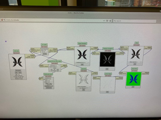
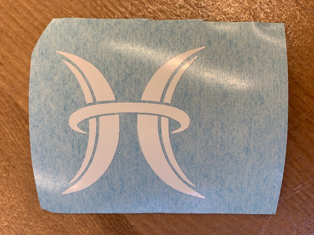
I then export the image as a PNG and port it to the Linux computer connected to the Roland vinyl cutter with a USB drive. I open up the modserver and the webbrowser and import the PNG file. I can change the size of the image when it actually prints by modifying the dpi value (I set it to about 3"x3"). When I click calculate, mods calculates the tools path and as long as the port is open, I can click "send file" and the image will print. Before I do that though, I need to make sure the rollers on the cutter are in contact with the vinyl and that the origin is set to an okay location.
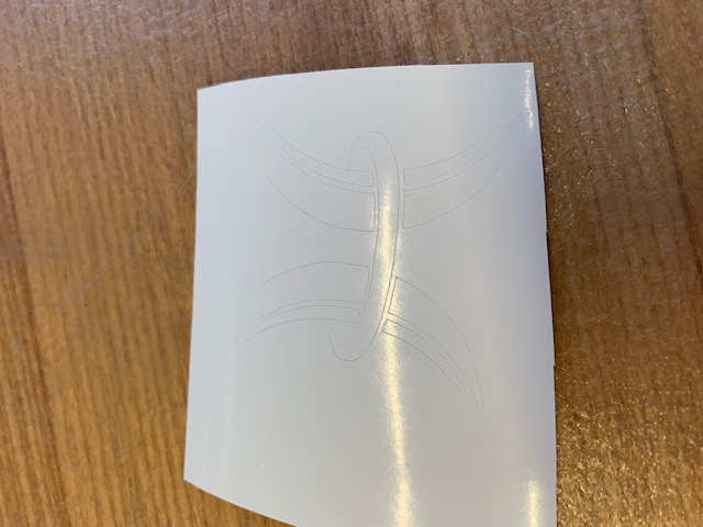
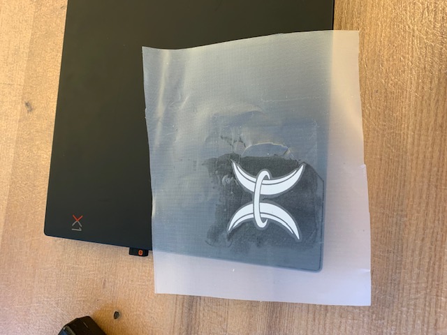
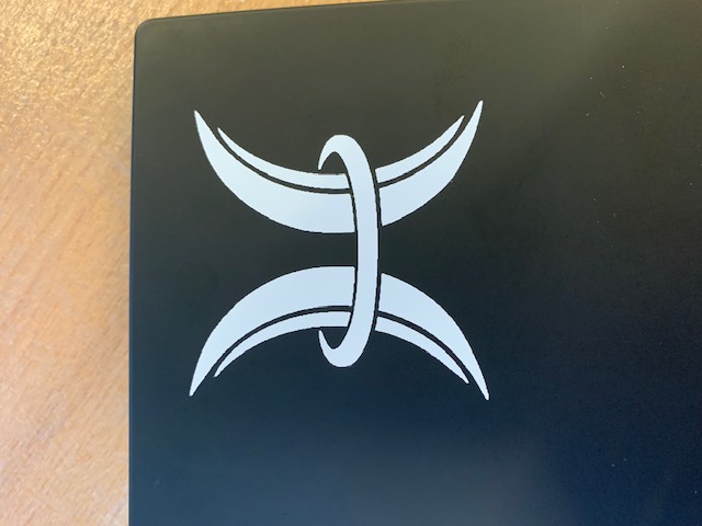
Once the logo is finished, I use scissors to cut out the section. I then carefully shear the surrounding material off with tweezers, place the logo down onto transfer paper, remove the backing of the sticker, adhere the whole thing to my laptop lid, and carefully peel off the transfer paper at a very sharp angle (almost flat) and with the help of tweezers to hold the sticker down occasionally. Once the transfer is removed, I apply pressure and ensure the logo is properly stuck to the laptop lid.
Design files for this week can be found here.