10 | Ouput devices
For my final project, I want to modify a 3D printer to produce multi-colour prints. My current plan is to attach a second gantry to an existing 3D printer (maybe an Ender since they’re so cheap) and mount an inkjet printer head to that. Then in the slicing stage, I’ll tell the printer that after it deposits filament it should move the bed to under the inkjet head and I’ll apply colour to the outer layers hence creating RGB multi-colour prints. See my inal project for more details.
To start working on this I decided to try to make a stepper motor controller this week, the fact that I had 2 midterms and needed something relatively straightforward wasn’t a disincentive either!
Creating the board in Eagle
Unfortunately, it’s currently 2022 and there are massive supply chain issues with silicon chips. Up till now, this had been just something I’d heard but never seen, but it’s affecting even HTMAA as there were no DRV8428PWPR in stock. These would have been ideal since they are stepper motor drivers with support micro-stepping, everything I need to move an inkjet printer head over a 3D print.
Instead, Neil provided a design using H-Bridges to make our motor driver. Anthony had told us to be wary about using the 5V from our laptops to power any circuit which also ran with other voltages, for the risk of mistakenly sending 12V to your laptop and frying it – a mistake that Anthony continuously reiterated MIT would not pay for.
This isn’t a concern in Neil’s board since he powers the motor directly from the 5V port, however, with 5V the torque on the motor will be very small – potentially not large enough to move the heavy inkjet printer head. So instead I decided to cut the 5V port on the USB – and therefore only use it for data transfer – and use a barrel jack connector for power.
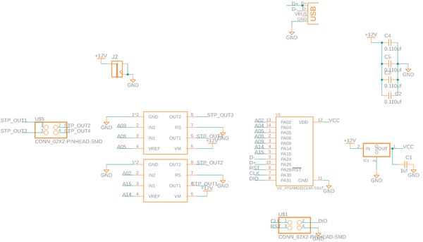
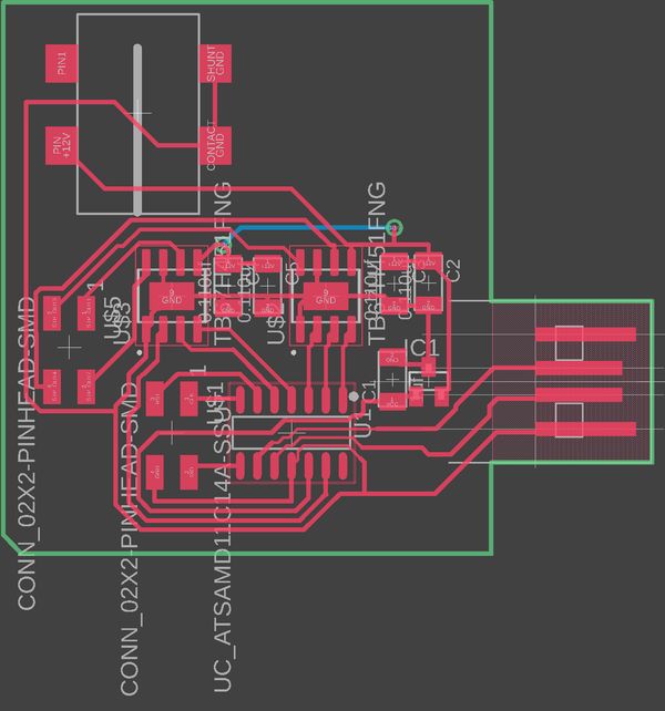
I then placed all my components into the Eagle Schematic, created a PCB, and routed them there. Like always I had a lot of trouble setting and changing trace widths. Not specifically, Eagle trouble. I would always forget to increase the width of the traces after making them small enough to get under the microcontroller.
What is a stepper motor and H-Bridge
After designing the board I went to show it to Anthony. Upon seeing it he instantly saw a couple of issues which I hadn’t due to not understanding what either a Stepper Motor or an H-Bridge was doing. So first, what are a stepper motor and H-Bridge?
A stepper motor is a type of brushless motor. Like all brushless motors, its rotor (the bit that does the rotating) contains a permanent magnet and is placed in the centre of an enclosure surrounded by magnetic coils (in my case two). By varying the current going into these coils we can induce magnetic fields. To get the rotor to go 360 degrees we need to continuously reverse the current so that we flip the coil polarities causing the permanent magnet in the rotor to chase the, unlike fixed poles.
A stepper motor specifically has some notable differences, it doesn’t want to rotate continuously. Instead, we want to rotate for a fixed amount of steps. When current is applied it hits a series of coils arranged in a specific way so that the motor rotates by a fixed amount. I was told the stepper motors we had could do 200 steps per rotation or 1.8° per step. If you want to rotate by fewer degrees you need to microstep by applying a lower current and turning on and off the coils non-linearly.
There’s a lot I’m still missing or getting wrong about stepper motors which I’ll look into another time. If you’re interested I thought this guide was good: What is a stepper motor?
An H-Bridge is a circuit which can change the direction of the voltage and hence the current applied to a load. We use it since we need to continuously change the direction of the current going into the stepper motor to change the polarity of the coils. It contains two input pins, two output pins, two ground pins, one voltage pin, and a VREF pin. The last pin is super important since it controls the voltage of the output pins.
I also need to look into these more, I briefly followed the guide at Controlling a DC Motor using an H-Bridge
Fixing the issues with the H-Bridge board design
In Neil’s board, however, the VREF pin is hard-wired to 3.3v. This was likely done since a) the board powers the steppers with 5V max anyway and b) It allowed the traces to be nicely routed under the microcontroller. This wasn’t going to work for me so I attached each H-Bridge’s VREF pin to a specific pin on the microcontroller. As well, in EDS we didn’t have the 4x1 connectors Neil uses so I changed mine to the 2x2 connectors I use for programming the board
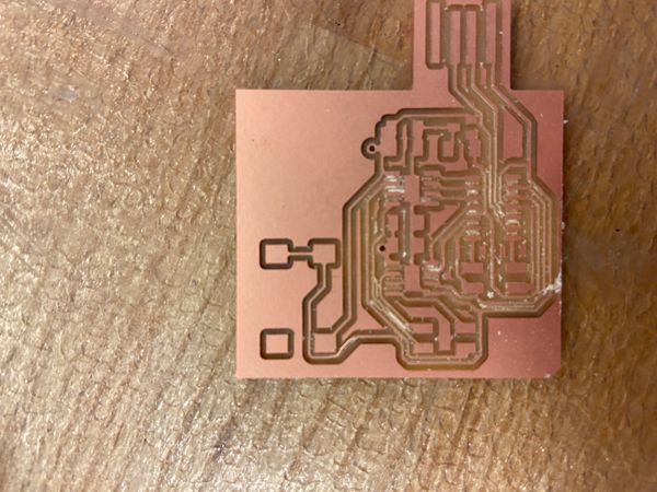
Milling the board
Like every week I had a ton of issues with this, most of them my fault I guess. I try to use the OtherMill in metropolis as a) It never gets used so it is pretty lonely b) I get to learn about the specifics of the OtherMill which will come in handy once HTMAA ends and I’ll no longer have Anthony to pester with questions.
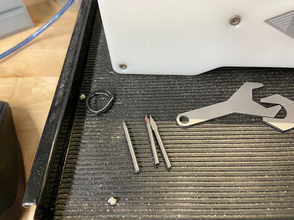
Unfortunately, the downside of my experimenting with the Metropolis OtherMill is my boards often come out horrible as I forgot important things. For this board, I had a via and since I’ve yet to get around to finishing my LED multiplexing board I wanted to get that working. Firstly, I needed to install the PCB bracket which makes it super simple to flip the board after milling the top and keep it positioned so the bottom can be cut in the right places. Once the bracket was installed, I needed to tell the OtherMill where it was. To do this it asks for you to insert an endmill upside down, and it’ll use the conductive shaft to figure out the location of the edges and back. However, when I tried to do this last week I inserted the endmill too far up and when I took it out the bit was broken :(. This week, I instead routed through our end mill drawer to find a dedicated probing bit. Once inserted, I probed the board and was good to go.
I thought! Unfortunately, in my excitement, I forgot to turn off the cut outline so my board milled great but it wasn’t possible to flip it over to get the bottom.
So I started a new job this time with only the traces and holes. Strangely though halfway through when I looked over the bit was just hovering midair and I realized that the 1/64” end mill had broken. That was Metropolis last 1/64” so I searched Google for what to do and it recommended using the PCB engraving tools which are faster and give better finishes. I put one of these in and it’s soooo much faster. With the 1/64” (and 1/32”) it takes 22m but with the 0.005” PCB engraving it takes 11m.
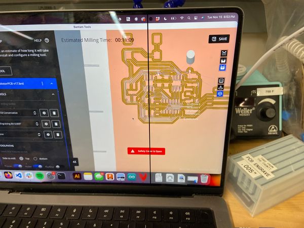
I was super happy at the start until my board came out, and it was terrible. The bit went way too deep at some points and since it is tapered this meant that the traces became incredibly thin in some cases just ripping off the board. I went to EDS and put it under the scope to see the damage and it was unusable. I talked to Anthony and he told me that while you can get terrific results from the engraving bits you need to finely calibrate the cut depth. I used 0.15mm but next time I’ll try 0.075m and go from there.
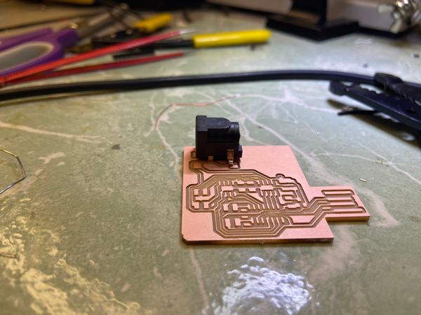
Soldering my board
At this point, I was running out of time so I decided to just go with my initial board and use a jumper wire. I headed to EDS and soldered everything onto my board nice and quickly until I went looking for a power jack. We had none so I took a trip over to Arch shop and got one of theirs but when I came back to EDS (I had forgotten my board) it had the wrong footprint. After that, I soldered wires to pins and just a screw-terminal barrel jack.
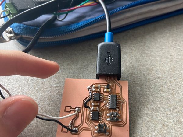
Programming the board
This part took a ridiculous amount of time. Most of it is my fault. When I tried flashing the board it gave me the classic errors and after probing my board and verifying I wasn’t shorting anywhere I realized that I had placed the board on the wrong way. Embarrassingly when I went to flip the board around I again soldered it the wrong way! Basically, the label has a dot on one side and something which looks suspiciously like a dot on the other. After finally getting the microcontroller on correctly, and fiddling with the Atmel wires I flashed it.
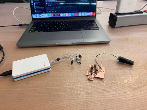
Programming the board
After much USB jiggling, I was able to see my board in Arduino. I copied over Neil’s stepper motor code and then wired my stepper motor.
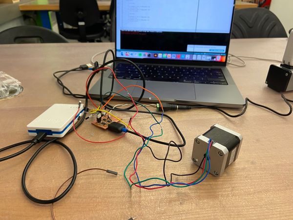
Then I uploaded the code and the stepper moved, yay!