09 | Input devices
This week was all about input devices. I’d had some experience with breakout boards for Arduino which let you measure temperature (with thermistors) or acceleration and tilt (with an MPU) but during lecture we learned about how to build our own versions of these sensors.
Capacitive touchpad
To start I wanted to make a capacitive touchpad. This had been done a ton by other HTMAA students so there were example boards and demonstrations of how this would work:
Unfortunally, while the two Matts implemenations of capacitive touch sensing is super cool they are sparse on details. I didn’t give myself nearly enough time for this so I started looking into the physics behind these circuits on Monday and got lost pretty quickly.
I then decided that I would just design the board and come back to try understand it later. I wanted mine to roughly match the grid Matt Blackshaw had made but I wanted my sensor on the pcb board rarther than with vinyl.
Custom SMD part
In Eagle, I started a new file and quickly realised that I had no clue how to make my own custom pads. After a brief goolge, it didn’t seem like there was a fast way to do this instead everyone recommended that I make my own library. Thankfully Adafruit has a nice guide for how to do this.
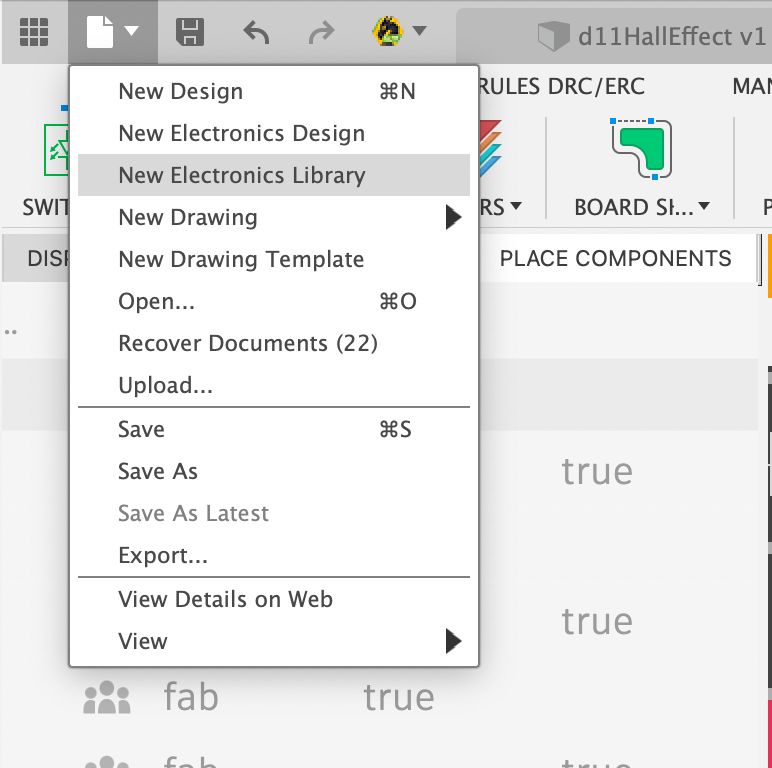
First I created a new library by going to File > New Electronics Library.
Then I needed to create a new package. This is where our new footprint and schmematic will live.
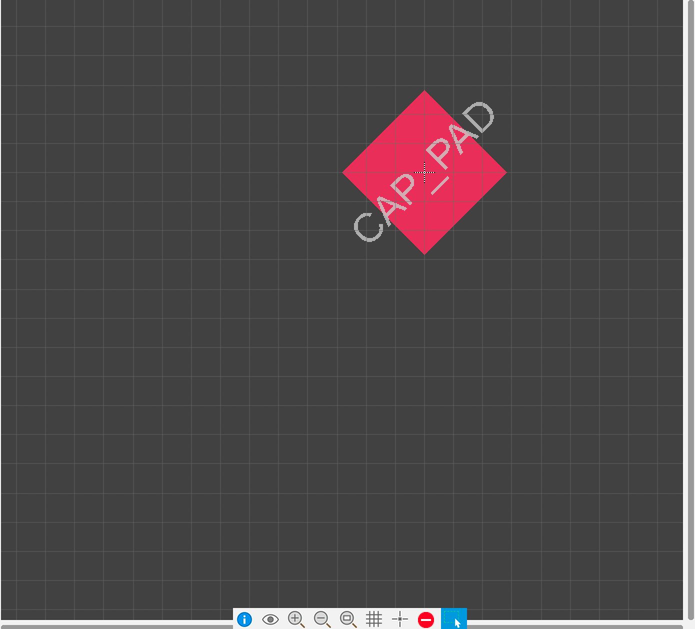
I didn’t need any specical 3D model for my capacitive touch pad so I went immediately to create footprint. Here I created an SMD pad (Place > SMD Pad) and changed it size in the side editor which apperared to 100mil x 100mil which is 1cmx1cm. I also wanted a nice aesthetic so I rotate the pad by 45 degress.
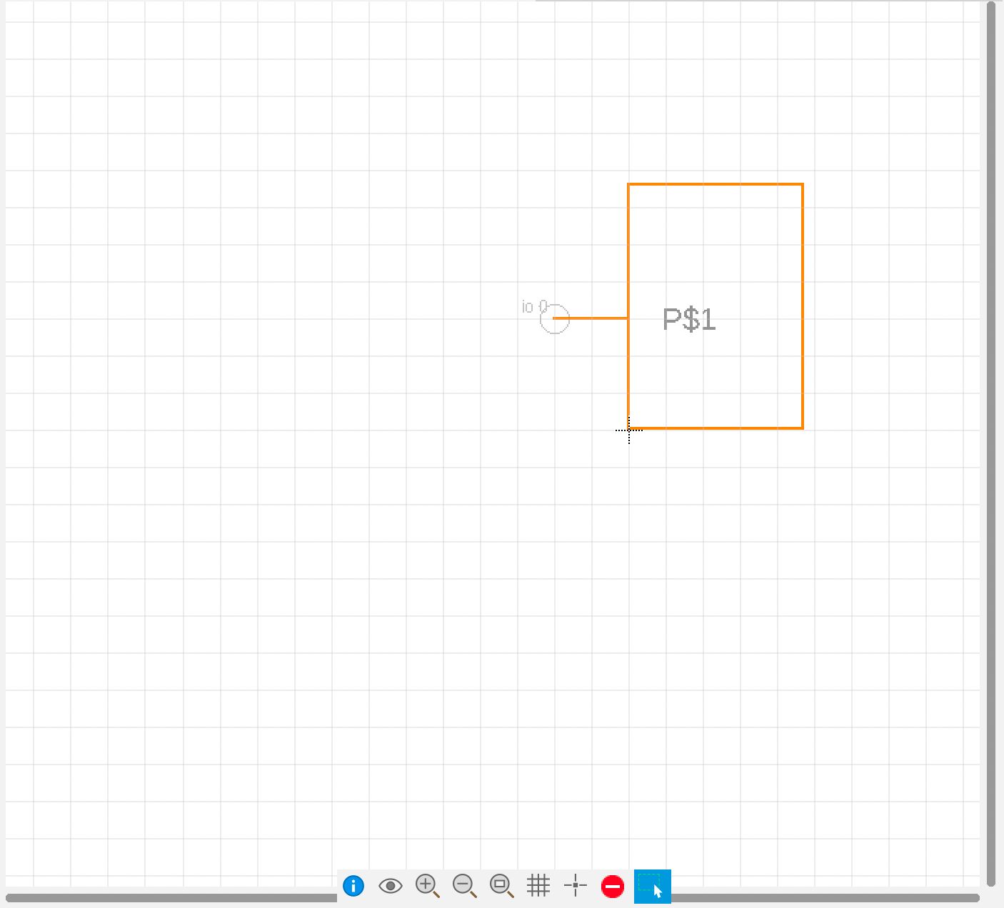
With the SMD pad made I now needed to make it’s symbol. I switched to create symbol (Create new symbol) and used the wire tool to create a box. I also needed a pin (Place > Pin) where I would route my wires to.
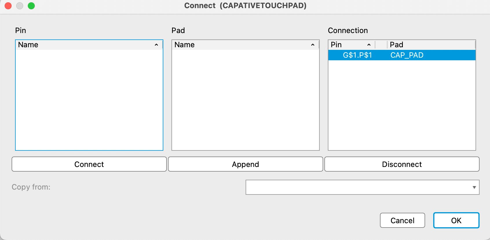
Finally the last thing I needed to do was connect my footprint and symbol. This is done in a device file (Create new device). Here I added my schematic and footprint and then associated them together by clicking on Connect and then selcting my pin and pad. After that I was done, I added the my new library to Eagle and began making my touchpad.
Designing the touchpad
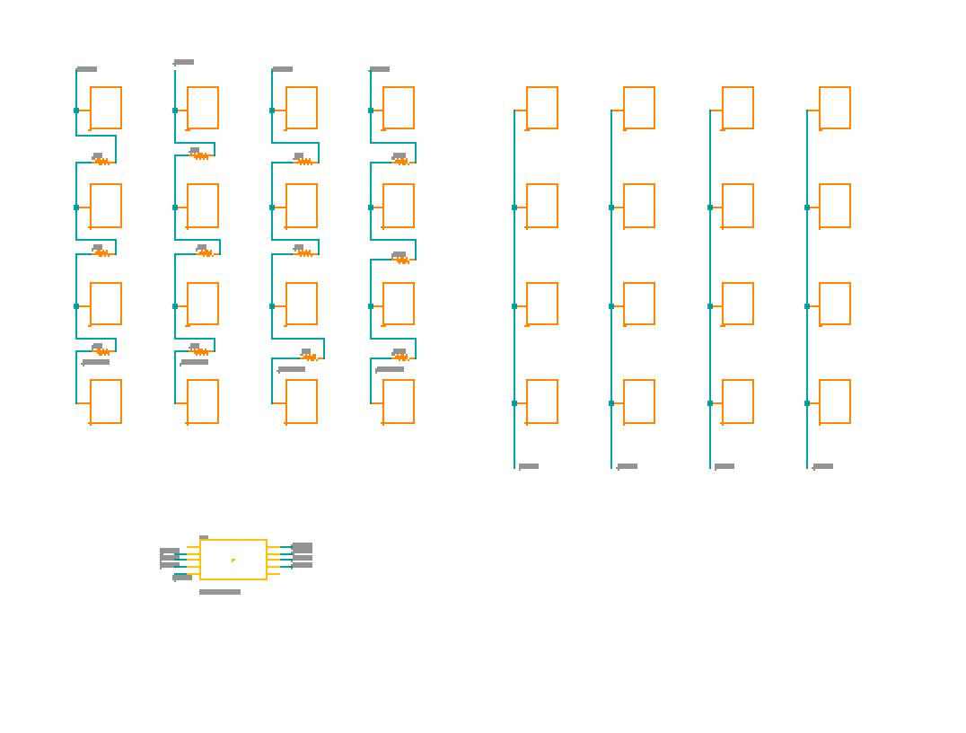
The schematic is super simple but I did get to use Eagle’s new pattern tool which made copying and positioning the pads in the schematic super easy.
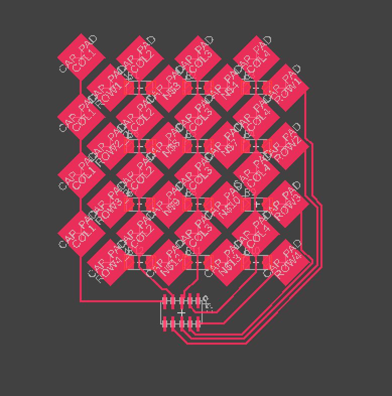
Unfortunally, eagle doens’t support patterning while routing which meant that I had to individual move and align each pad and for the rows a 0ohm resistor to jump over the traces for the column.
Understanding how the board works
At this point I had my board complete but I still didn’t fully understand how it worked. I’m pretty sure I need to add resistors somewhere between the input and output bins on the board I’d use with this grid but this week is super busy with 3-day notice psets and a midterm so I knew I didn’t have time to explore this further.
Apparantly lots of people wanted to work with capacitive touch however so a HTMAA TA put out a small guide.
hall Effect sensor
Designing the board
Instead, I switched to designing a hall effect sensor board. I thought Neil’s demonstration of positioning objects in 3D was super impressive with these and depending on how I implement my inkjet 3D printer I may need to build endstops / know the position of the inkjet printer head and hence could use this sensor.
As I was in a little bit of rush (it was Tuesday by now) I decided to keep things simple and followed the example hall effect with the D11C board. Using a Attiny is something I should do in the future, but I didn’t want to have to mess with setting up how it’s code is flashed.
Using my previous eagle files and the diagram Neil provided I quickly create the schematic and routed the board. In Neil’s version he has a trace which runs under the 3.3v regulator, however this was too small for the Othermill so I switched to a 0ohm resistor.
Milling the board
Milling the board took a while as I unfortunally broke a couple of endmills, for entirely stupid reasons too. I forgot to close on the boxes and then while trying to take on and off the different screens hit it with my hand and broke the two endmills inside.
Then I had issues with positioning my board correcly, someone had left on the pcb bracket but I didn’t realise that I needed to probe this to get the positioning correct. At one point the Othermill moved over the bracket and started coming down. Thankfully I was looking at the machine when it did this and stopped it quickly but not before it hit the bracket and destroyed the endmill.
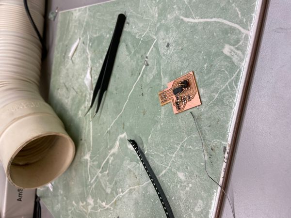
After about an hour though I fixed everything and milled my board.
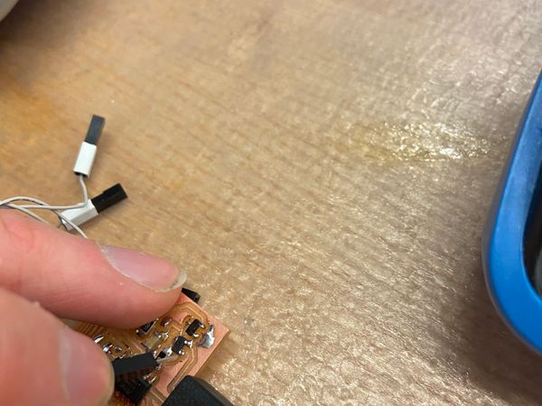
Stuffing my board
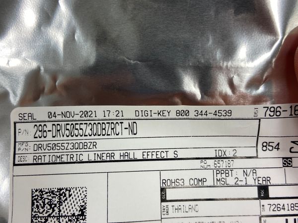
Stuffing was a breeze and it’s cool to see how much faster I can do it now than during the second week. EDS did not have the exact hall-effect sensor which I used in my schematic (A1324 four) but the one they did have was roughly the same size and after checking it’s schematic had the same pin posititons
Flashing the bootloader board
I decided to use the 2x2 pin connectors to conserve space but this meant I couldn’t use the ribbon cable I had been with the Atmel-Ice. Thanfully, Anthony had broken out the Atmel’s cable into indivdual strands to handle any connectors.
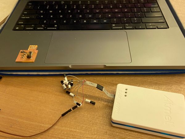
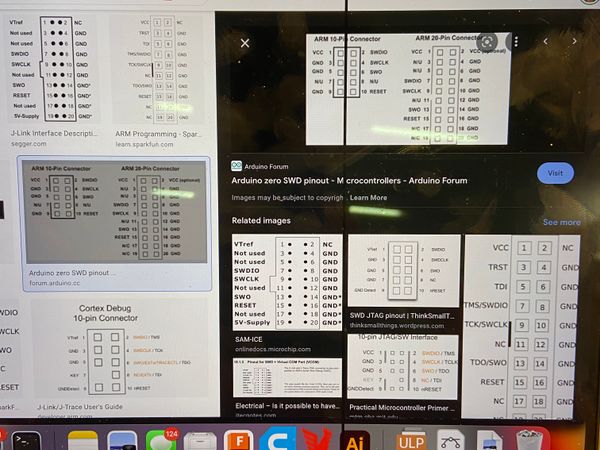
I looked up the SWD pinouts and matched the numbers from the graph with the numbers on the cables and the pin they needed to go in
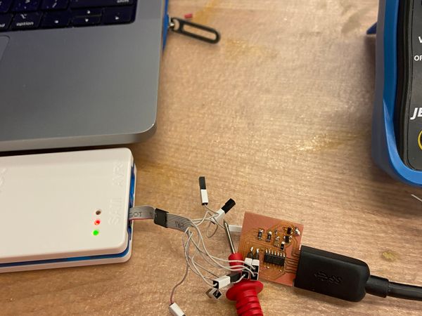
This didn’t work the first time since the Atmel requires that it’s VCC pin be provided with 3.3v and the 2x2 doesn’t have a pin for this so I had to put a jumper wire into the 3.3 wire and connect it by hand
Programming the board
I copied Neil’s hello.mag.USB.ino code into the Arduino IDE and uploaded this to my board
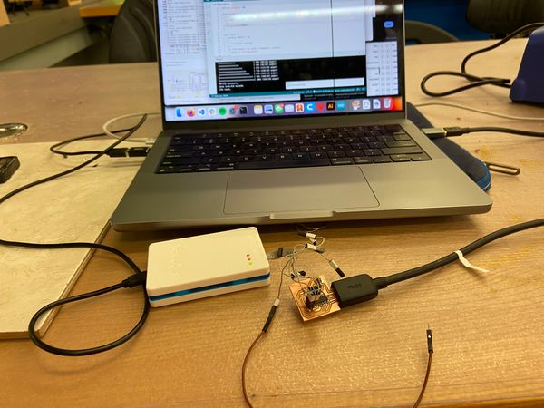
To see the visualization I downloade the webpage and javascript server Neil created. These must of been made a while ago as when I tried to run it with node I got tons of errors, once I uploaded all the libraries everything connected and when I brought a magnet close the values changed!
