Demo
Design
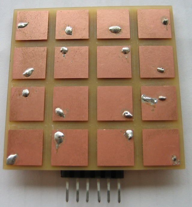
For this week's assignment, I made a 4x4 capacitive multitouch grid. Designs like the $4 touchpad are limited to a single touch - with multiple touches, it is impossible to tell which row is associated with which column (unless you do sneaky things with mutual capacitance, which is a whole 'nother barrel of fish).
The board works using the "charge a pad through a large resistor" strategy. The charging profile of the pad relates to an RC time constant - since R is large, small changes in C can be detected.
Schematic
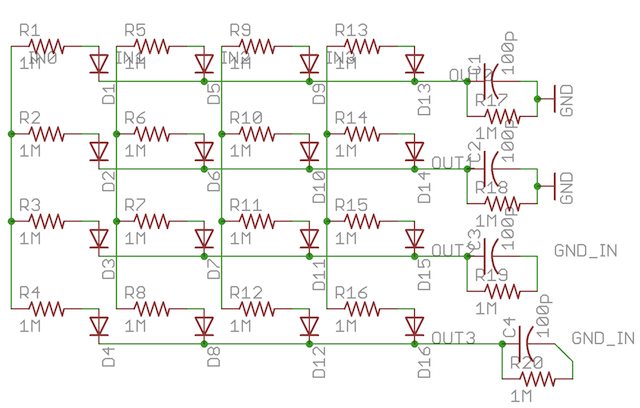
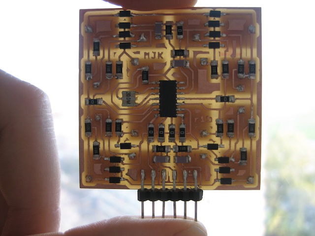
As it turns out, capacitive grids are tricky, because capacitance tends to leak wherever it can. The grid is designed so that columns share an input and rows share an output. I used diodes to isolate each pad from the neighbors on the same output row.
In the interest of board space, I didn't isolate each pad from the inputs. This meant that I could measure charging behavior in isolation, but discharge behavior is contaminated.
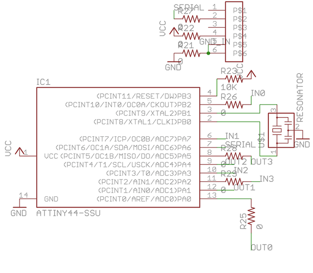
I used an Attiny44 to control and communicate with the grid. It also sends data back to the user's computer through an FTDI serial link. The total cost in parts ended up around $5.60
Layout
As you can imagine, wiring the traces required patience and sneakiness. I used a bunch of 0 Ohm jumpers to leap over traces when necessary, but the routing ended up pretty neat (and often symmetric).
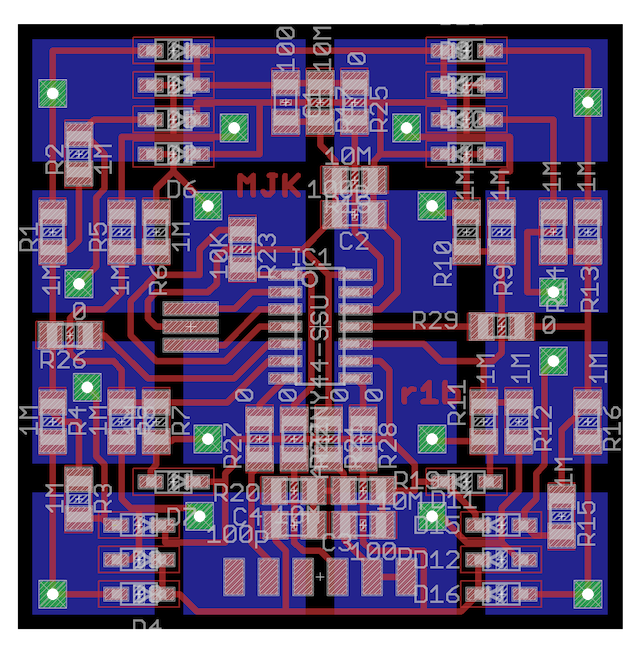
The sensing pads are on the opposite side of the board as the components. I used a a Makefile and Python script to export the via image then stitch it into the board cutout outline, so the vias were all cut out at the same time as the board. Since the board is symmetric, I could simply flip it over into the original cavity to mill the sensing pads. Registration didn't need to be very precise since the pads are large.
Population
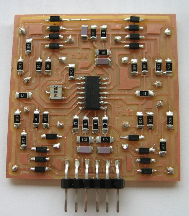
The only interesting part about populating the board was the vias: I electrically connected the vias by carefully threading solid wire through the holes, folding it at a right angle on one side, then soldering. If you don't fold it at a right angle, it has an unfortunate tendancy to fall out.
Firmware
I used the ADC to measure pad voltage one micro-second after setting the sending pin high. Due to the ADC's sampling time, I couldn't measure an entire column in parallel; instead, the code samples each of the 16 pins individually. It sends data back as a stream of 16 characters (only the top 8 bits of the ADC result are used) with a newline in between readings.
There's some interesting pin driver twiddling - I exploit the difference between input (high impedance) and output (low impedance) to manipulate how the circuit charges and discharges.
Software
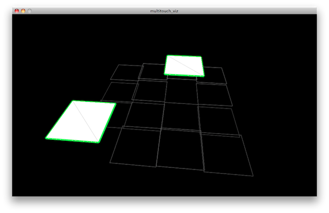
I wrote a quick sketch in Processing to display the pad states. At first, I had trouble with the serial library, as it kept complaining about RXTX version mismatches. The advice here helped resolve the issue.
Source

All source files are licensed under a Creative Commons Attribution-NonCommercial 3.0 Unported License.