Prior to attaching my output device (OLED device), I first worked with Anthony to resolve my issue with the laser TOF component (VL53L1X from the input devices week). While all the parts were soldered properly and the multimeter showed no signs of improper grounding, the Serial Monitor showed only "0 mm." Therefore, during week 9, I used an external laser TOF rather than the one I soldered to my PCB. After in-depth analysis through the use of an oscilloscope, Anthony helped me find the error, which was that XSHUT on VL53L1X wasn't HIGH in its voltage state, and thus, didn't produce any readouts. Therefore, by changing the pin to a HIGH state, I could use the component without a problem.
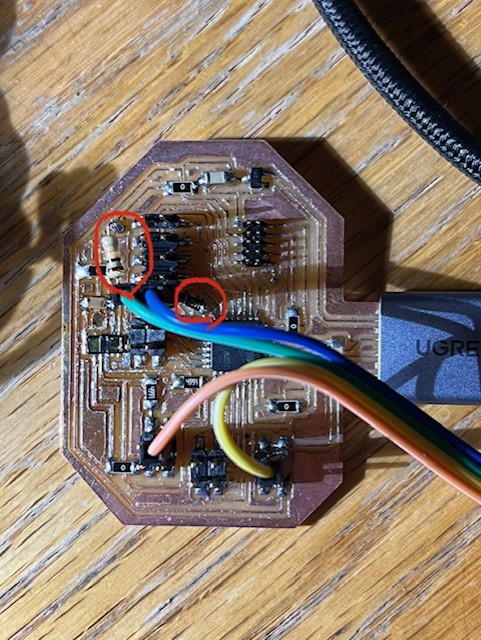
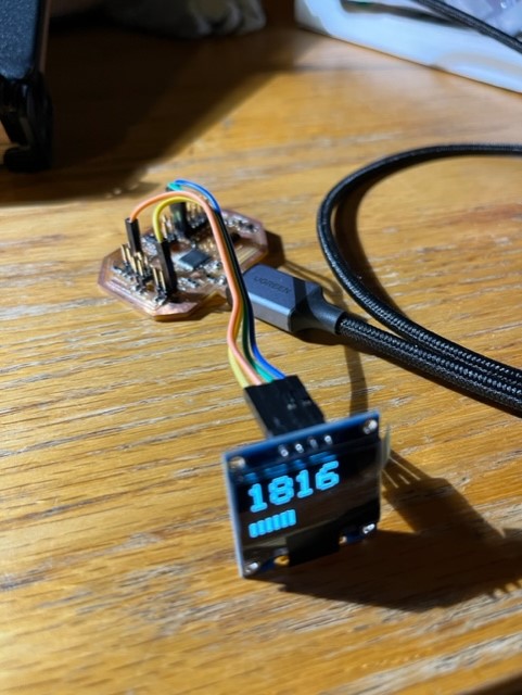
Using the SSD1306 OLED, I wanted to generate the distance shown on Arduino serial monitor on a portable screen (this will later be paired with an alarm sound). Luckily, I pinned out my microcontroller so I didn't have to re-mill a new board. I used pins 8 and 9 for the new SDA and SCL associated with the OLED screen. Moreover, I attached two new 5k ohm pullup resistors to receive a better signal (the image of the modified board is shown below).

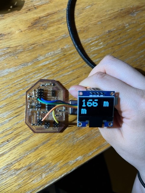
While writing my code, I guided my display based on Adafruit_SSD1306 example that showed how to use the SSD1306 OLED device. I encountered some troubles initially because odd symbols were shown instead of numbers. After changing the code from a "write" to a "print" statement, this issue was resolved.


The video of my functional device is shown below! The code for this week can be downloaded here, but I'm planning to add more features to the display for my final project.
Eventually, in the upcoming weeks, I'm hoping to attach a piezo speaker that can act both as a distance-based alarm and a honk (capacitor sensor). This part will be part of the final project.