I first wanted to make a medical device like the automatic syringe for its use in a hospital setting. However, after the computer-controlled machining week, where I made an OSD mini car, I changed my project to make a drivable car. (I'll make medical devices in a different class :) )
As of 10/20/22, I am very excited to develop the engineering acumen necessary to prototype an RC car.
SET FINAL PROJECT IDEA: wireless, remote controlled car!
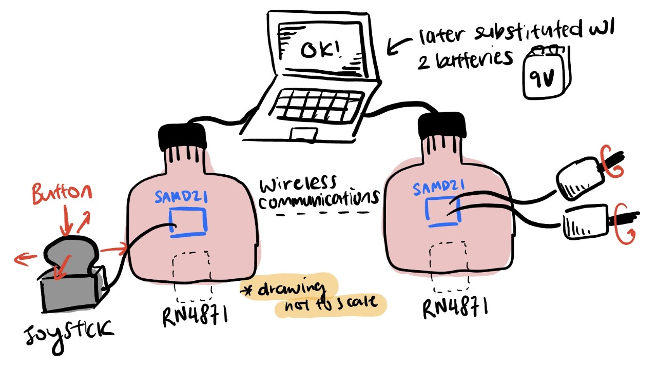
The car's motor will be controlled by a joystick. The process goes as this:
Joystick -> SAMD21 (microcontroller) Tx -> RN4871 (1) Tx/Rx -> RN4871 (2) Tx/Rx -> SAMD21 (microcontroller) Rx -> 2 motors' speed (A schematic of the process/car is shown below)
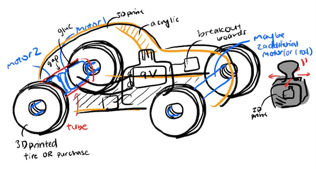
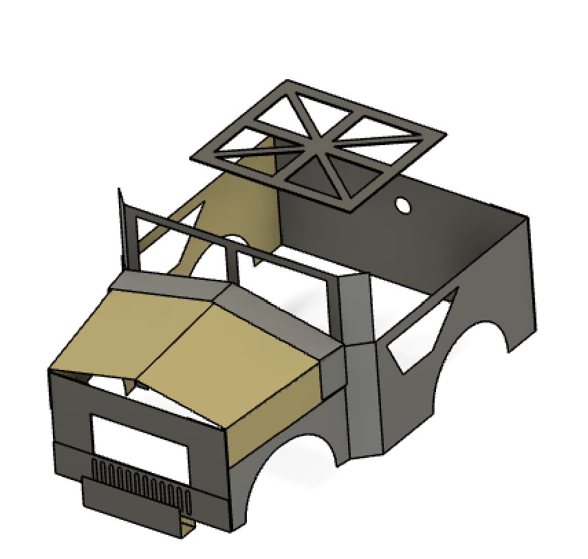
I resketched the car during my wildcard week to make it compatible with the material: steel metal sheet.
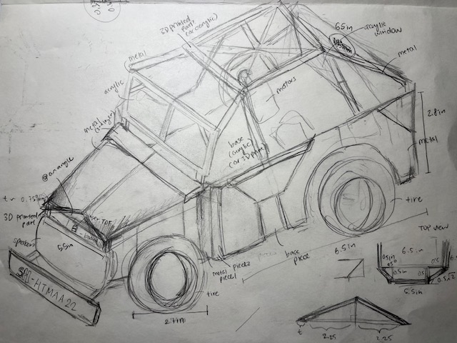
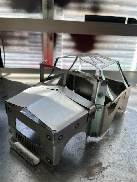
Initially, I was planning to 3D print my car, but after learning about the wildcard week where I got to learn about various metal works (Fablight laser cut, water jet, spot welding, etc.), I decided to create a steel-based car. The actual design and building of the car were completed in week 14, where I used steel sheet metal and welding to construct an approximately 6.5" x 11" car. Then, John helped me with sandblasting the surface, and I coated the car with clear antioxidant spray paint.
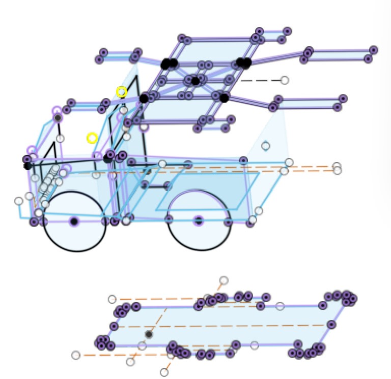
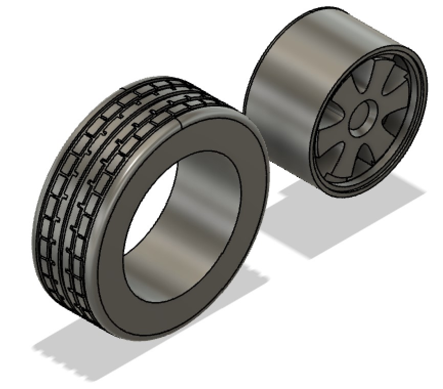
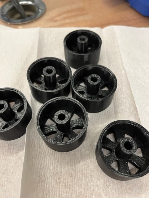
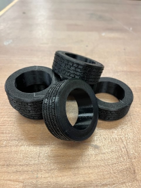
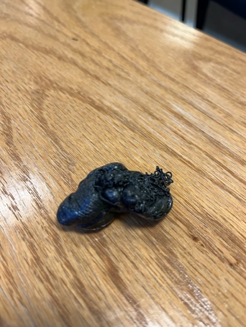
I wanted to purchase RC car wheels, but nothing was suitable for my car, so I decided to CAD my wheels. The rim and core of the wheel were 3D printed with PLA to provide stiffness. Then, I used TPU filament (flexible) to print my tire. Unfortunately, I ran through numerous hardware challenges because the Prusa 3D printer wasn't working as intended (an example is shown below for the car joints). The fact that some parts were small contributed to the difficulty in 3D printing. In the end, I became familiar with using 3D printers and adjusting settings accordingly (i.e. adding brims, supports).
Part Name |
CAD model |
Manufactured parts |
|---|---|---|
Wheel |
|
|
Joints & Mounts |
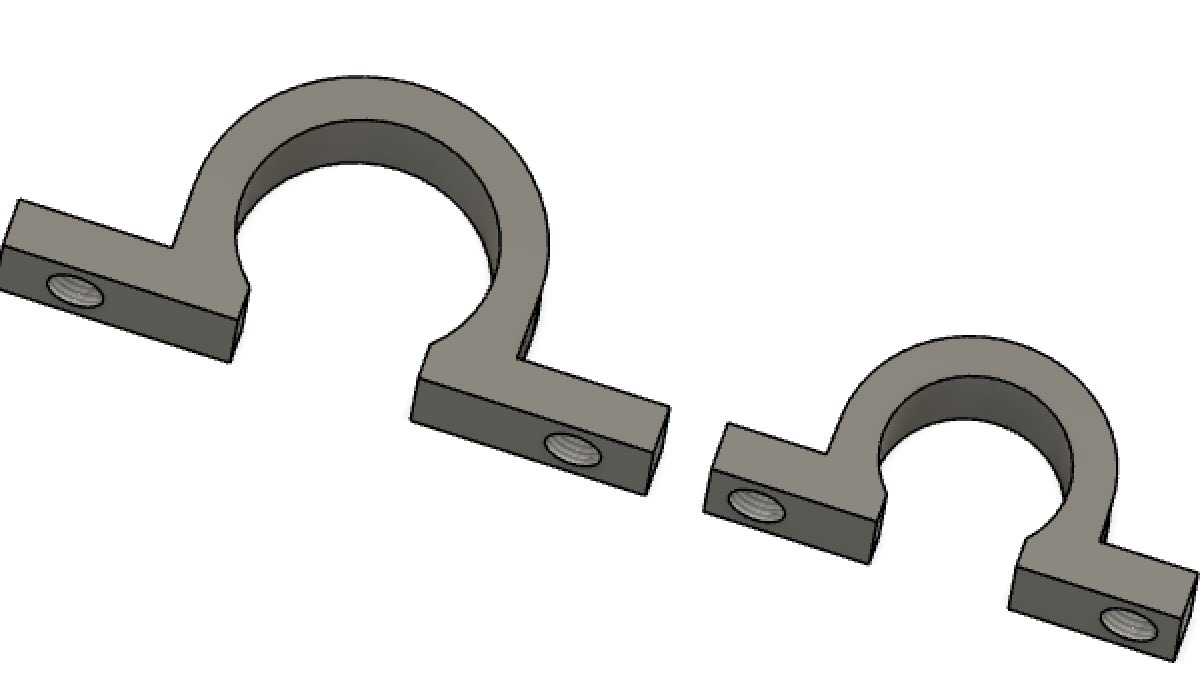

|
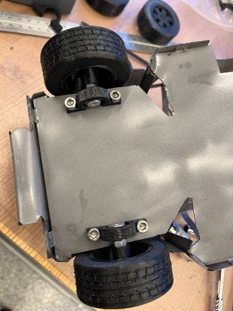
I ended up not using the 3D printed joints but instead used nuts and bolts because they were sturdier |
Controller |
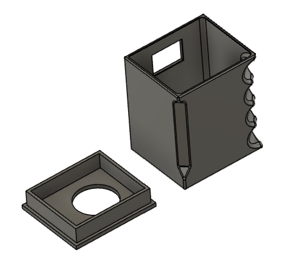
|
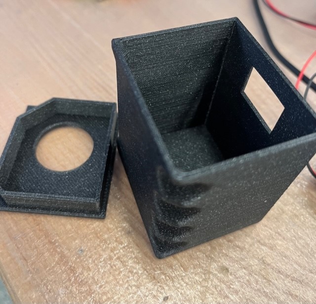
|
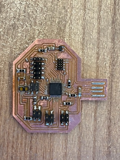
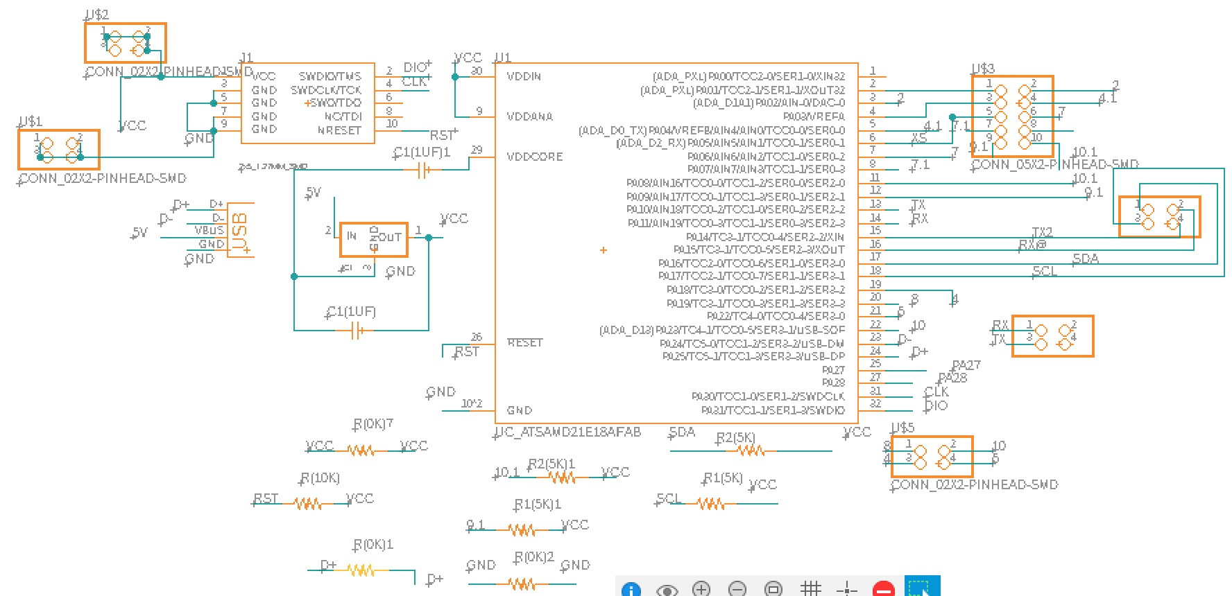
During the week9 (input device), I created a SAMD21E18A microcontroller attached PCB board with many break-out pins so I could use the same board for the rest of the semester.
Initially, my directly soldered laser TOF sensor wasn't working as intended, so I used these break-out pins and an external device to measure the distance.
Luckily, Anthony helped me debug this issue with VL53L1X. In the Arduino code, we needed to set the pin on HIGH mode because the component is automatically at a LOW state.
(refer to week10 (output device) for more information)
To have an external display of the distance, without using Arduino's Serial Monitor, I attached OLED to the microcontroller that will print the measured distance. Additionally, I made a user interface screen display of the distance, so that this information can be read on the laptop screen (refer to week10 (Output Device) and week12 (Interface and Application Programming))
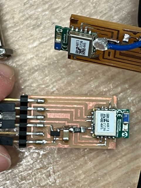
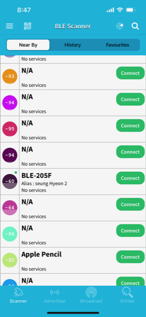
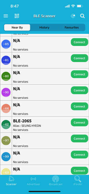
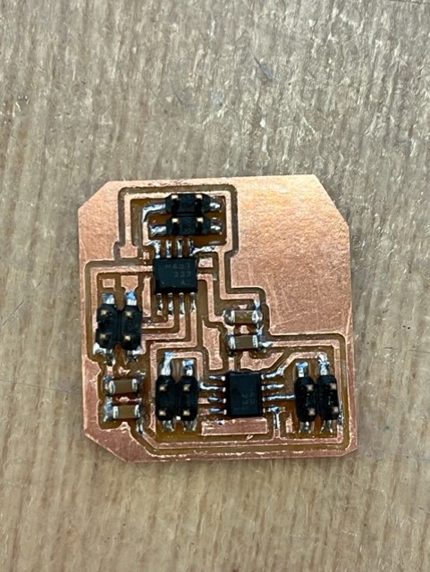
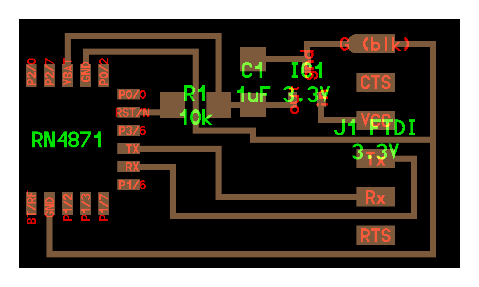
During my week11 (Networking and Communications) week, I created two RN4871 Bluetooth PCBs. Although it took many trials-and-errors to make my board functional, using two breakout boards (Neil's design), I was able make both of them work.
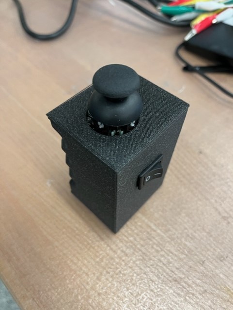
The joystick includes two potentiometers (changes voltage based on the angle) and one button. The range in voltage (given in 0 to 1023 bits) will be used to control the speed and direction of the car.
I referred to the joystick modules throughout my design processes. In summary, my code allows the microcontroller to read the potentiometer's analog values and print them out on the Serial Monitor. When the button is pressed, I commanded
Arduino to print out "2000," so that it's not within the range of 0 to 1023. Consecutively, these data are sent to the Bluetooth device for wireless communication.
Code to read and print out the Joystick data (will be sent to the car Bluetooth)
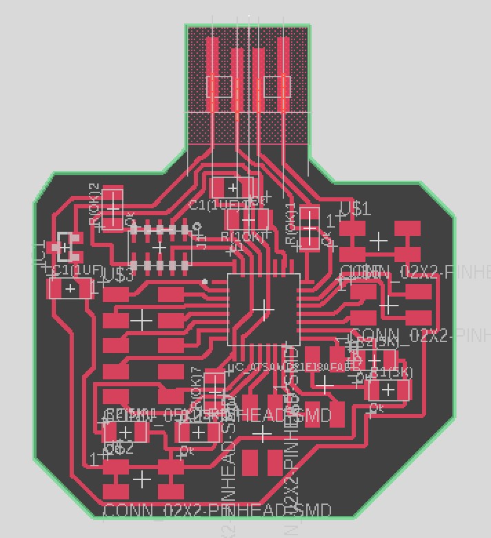
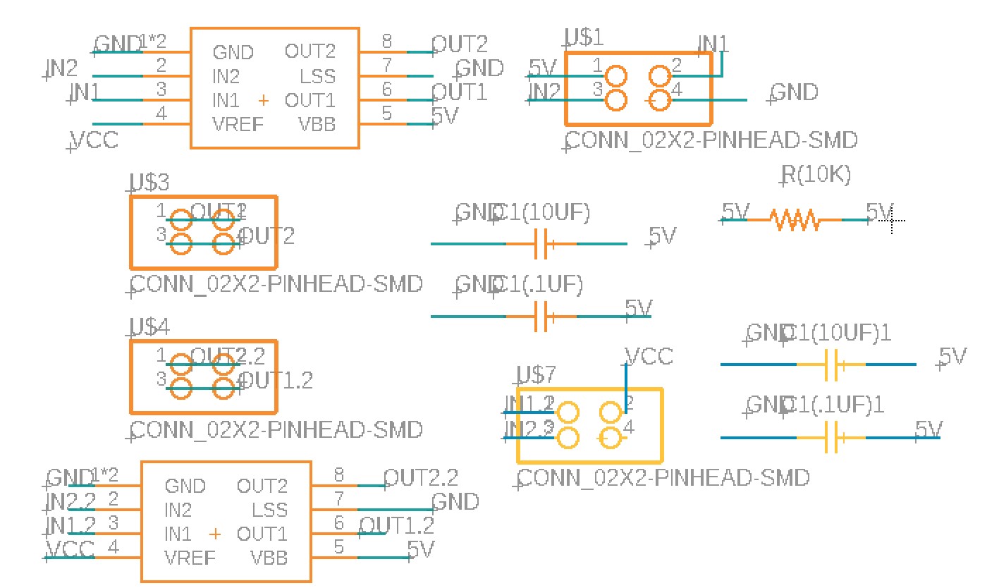
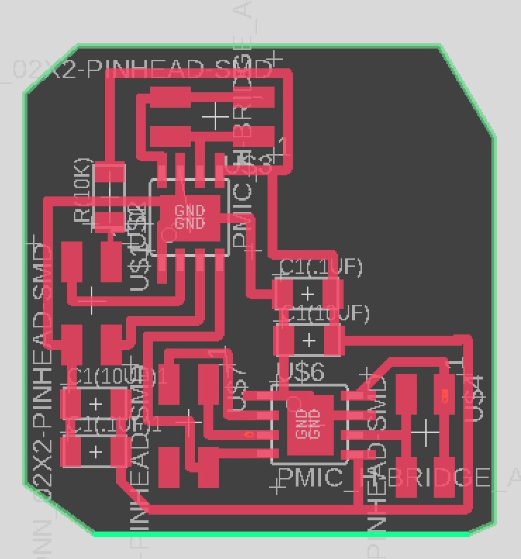
In order to work modular (as recommended by Neil), I decided to create a separate motherboard for my two DC motors and RN4871 Bluetooth device. The diagram below shows the schematic and design of the board using Fusion 360 electronics.
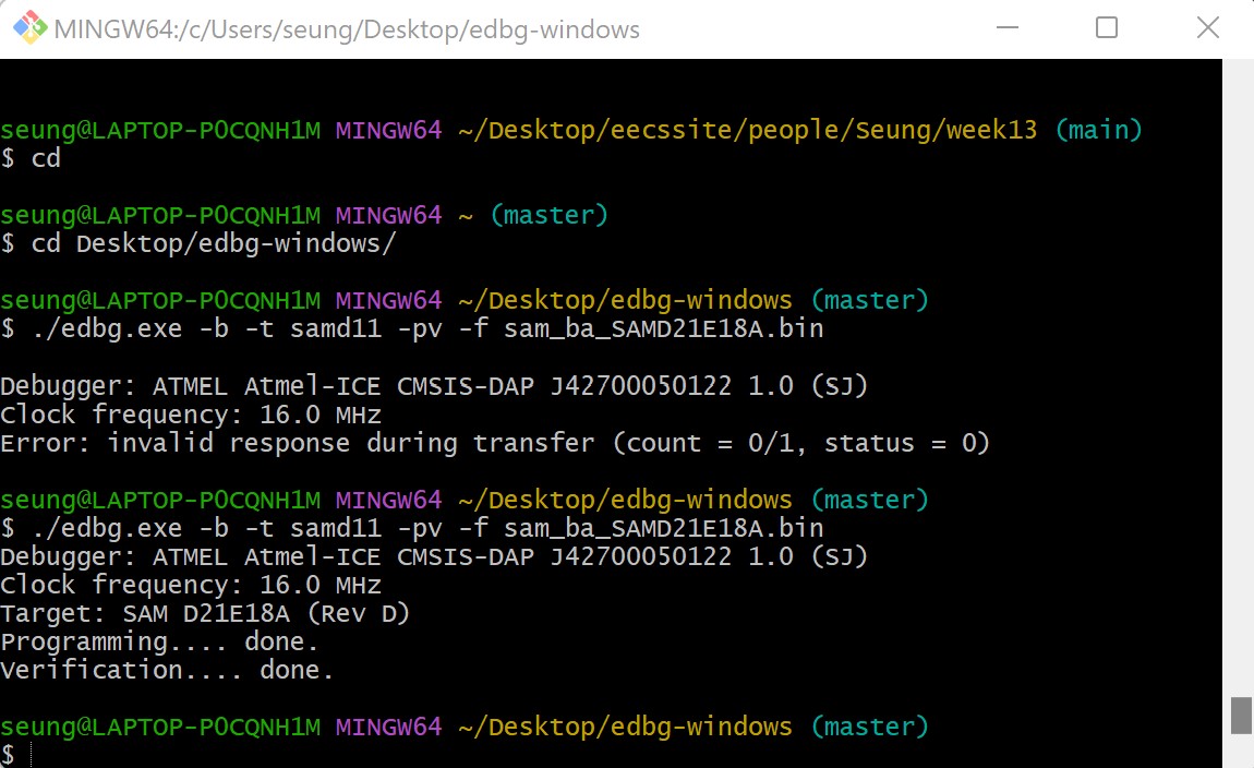
Soldered PCB & bottloader uploaded
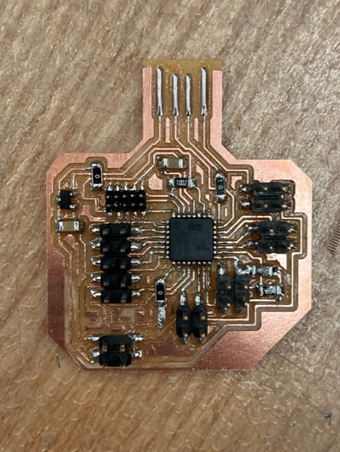
I will use two motors, one for the left and one for the right, to control the direction of the car. The PCB schematic and board design is shown below.
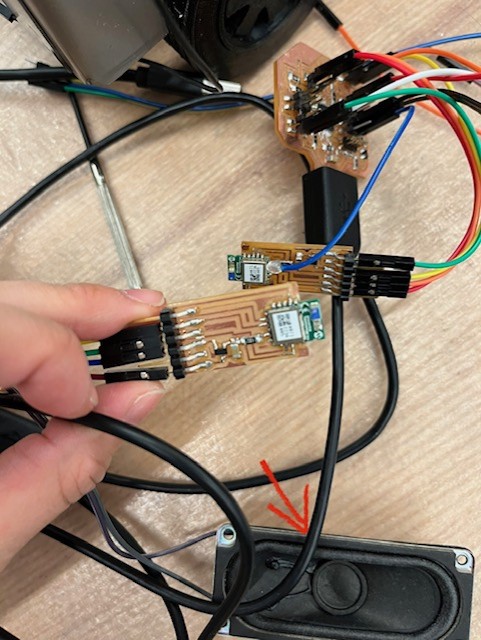
I soldered components on the motor board and connected them to the motherboard and motors to test if these motors moved as expected. I used an external power supply at 9V and specified the state of the motors for commanding movements like forward, reverse, and gradually increasing or decreasing speed.
Initially, I used digitalWrite() to indicate the state of the motors, but I changed to analogWrite() for more flexibility. I knew how to gradually move forward and backward as well as turn left and right at the maximum speed (for instance, when turning right, the left motor would move at a maximum speed and the right motor would be stopped).
However, coding to allow turning left and right at an in-between speed was confusing. Quentin and Anthony kindly helped me code for this issue (Code to control the car after receiving the joystick data).
Despite the coding change, the motors' and potentiometer's manufacturing flaws led to the difficulty in maneuvering the car as easily as I hoped. Nonetheless, I'm very glad that my car works wirelessly!
Finally, I implemented an external speaker that can make a honking noise based on the button state of the joystick. I used a frequency of 1000 Hz because this was within the range of usual car honks.
The code was easily done via the use of if statements (when the "input == 2000") and Arduino's "tone()" function.
On Friday night (12/16/2022 @10:00 PM), I accidentally fried my computer. I was tired from being in the lab and accidentally connected an external 18V battery to my 3.3V breakout pin, which burned my voltage regulator, microcontroller, and computer.
My computer was completely shut, and this was not the happiest moment of my life.
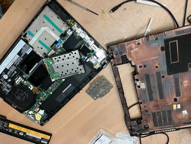
Fortunately, Guillaume (a fellow student in the EECS section, also an expert!!) helped me detach my SSD drive and store the data into a hard drive, and Anthony set up a desktop for me to use in the lab. After this chaotic hour, we put the SSD drive back into my computer, and "MAGIC!" my computer turned back on! Instantly, that day changed to a cheerful day.
Moreover, I must not forget to honorably mention Yuval, who made me a wonderful meme. I thank him for his creativity, time, and effort :)

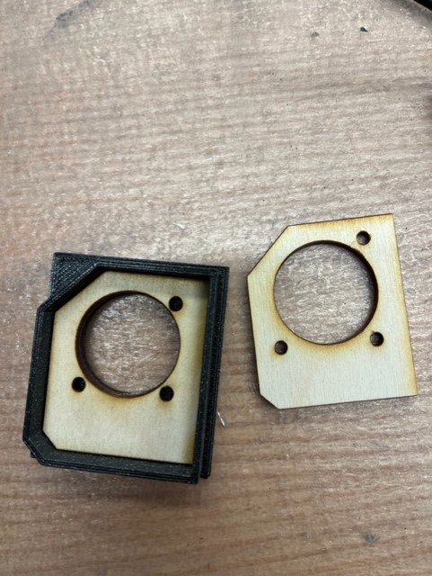
Assembling everything was challenging but exciting. I wanted to see the parts all coherently functioning together and especially as a bioengineer, this final project was very meaningful to go out of my comfort zone. I started by building the joystick and testing on Arduino that the connection was still reliable. I also used the bandsaw to cut acrylic and a laser cutter to fill the void with wood (which I didn't use in the end). I joined some parts using a glue gun and others by tight-fitting joints.
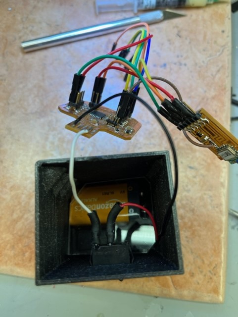
I used various lab resources (3D printed parts, hot glue, hot air gun, double-sided tape, soldering iron, wires, heat shrink, acrylic, nuts & bolts, etc.) to assemble the car. I approximate the entire cost of the materials to be around $65 to $85 (~$20 for steel sheet, ~$20-40 PCBs (including ones I had to remake), ~$10 for 3D print filaments, and ~$15 for others, including motors, OLED, glue gun, wires, acrylic, etc.)
Finally, I attached the batteries and tested my car!