
For my automobile, different input devices can be incorporated, including touchscreens, buttons to control temperature, play music, roll down the windows, open car doors, etc. The camera feature to sense the environment can also be considered a good input device. Out of these numerous options, I wanted to make my car scan the environment and based on the distance in which people/ objects are located, to make noise if they are within a certain proximity to the car (to prevent a crash). This would use a laser time of flight (TOF) sensor which gauges distance based on how long it takes for the light to bounce from an object and come back.
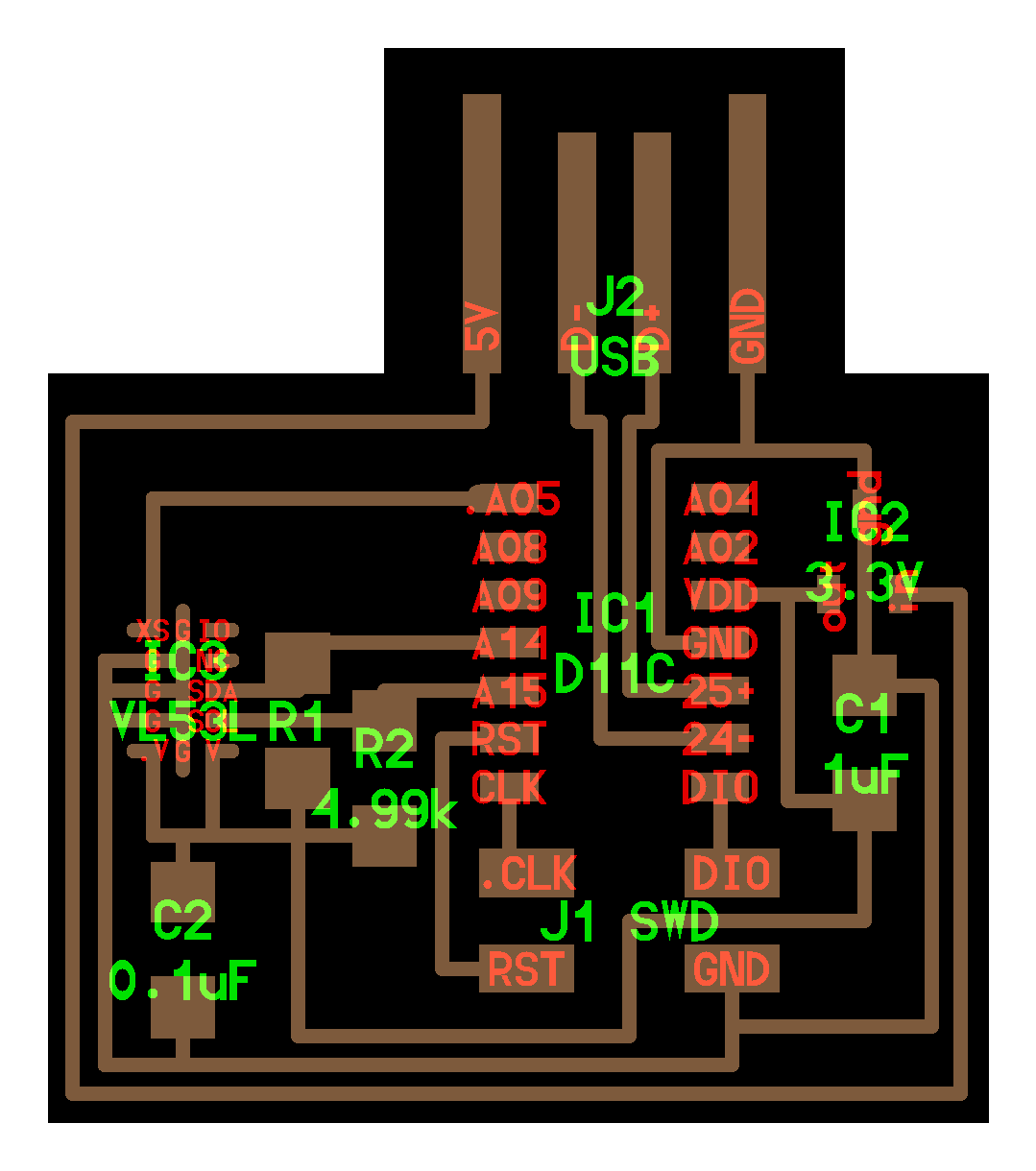
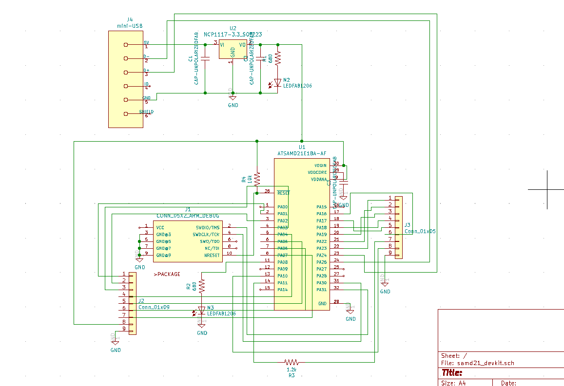
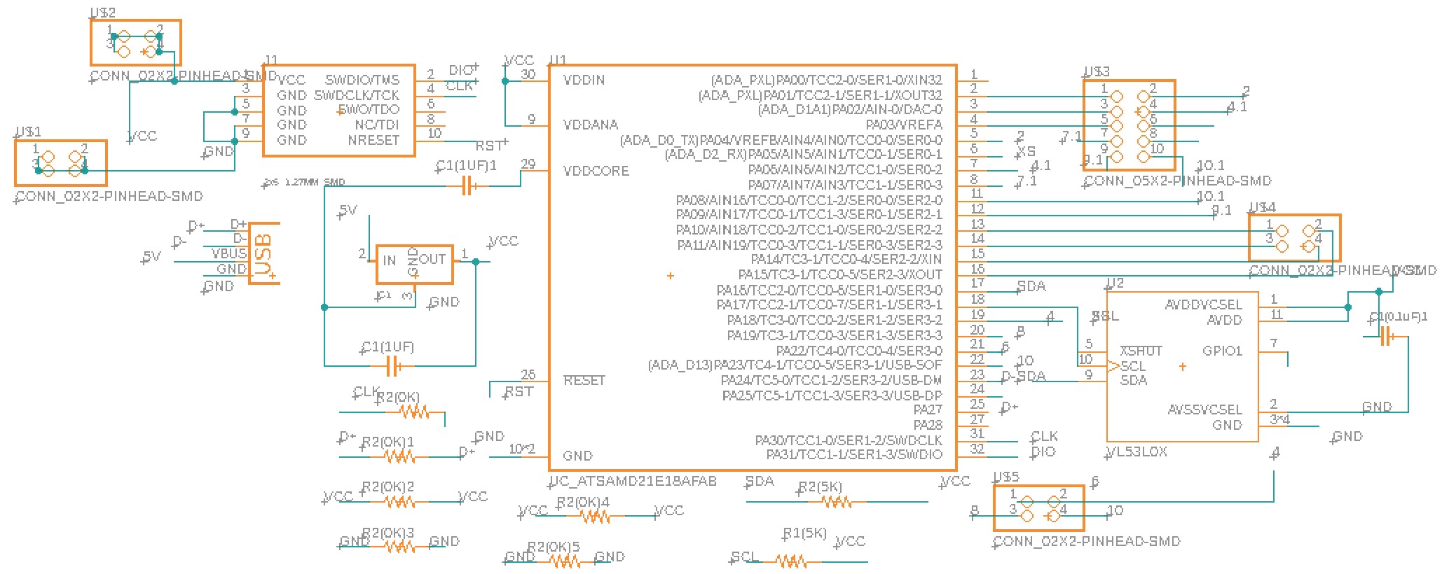
Referencing Neil's and Quentin's PCB boards, I made a schematic of my board. I wanted to include VL53L1X (laser TOF) and multiple connectors to allow the future use of most of the SAMD21E pins. I also needed to include multiple VCC and GND so I can use the same microcontroller for other subboards and connect via the wires. I carefully looked into how Neil and Quentin designed their boards and made mine accordingly.
As schematic also shows the VL53L1X component, which is connected to the microcontroller directly and the rest unused pins were pinned out via a 2x5 or 2x2 connect While designing my board, I struggled to wire the connection because it had many components. Still, I wanted to make the board as compact as possible, so I utilized six 0 Ohm resistors and 4 holes to make some connections.
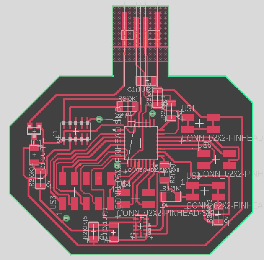
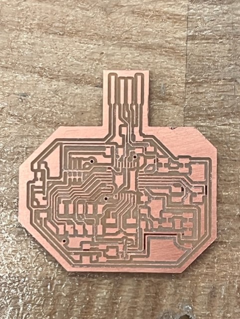
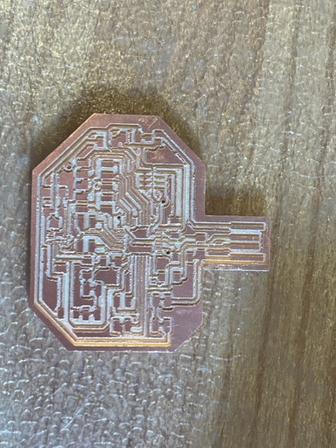
Since the board was much more complicated than my other previous boards, it took longer to mill (approximately 40 minutes). My first milling showed some signs of incomplete milling (left picture), which may have been due to uneven taping of the copper plate like what happened during week 7. Prior to re-milling my board, I edited my eagle board to ensure that the unmilled traces were farther apart. Luckily, my second board came out nicely and as expected (as shown on the right figure).
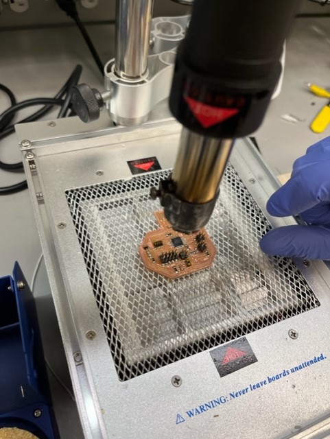
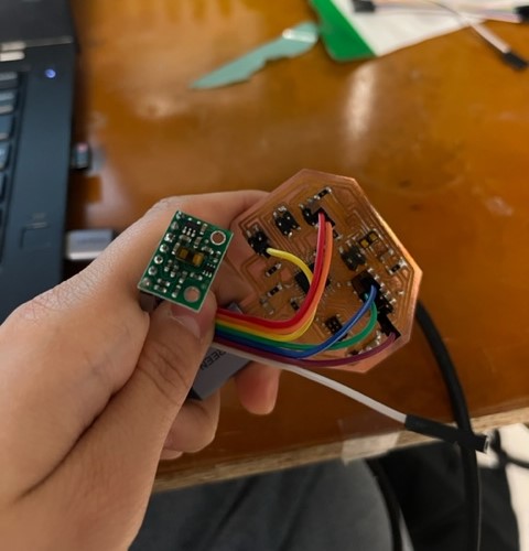
Soldering was an arduous process. I had many parts to solder, and attaching laser TOF was particularly difficult. Anthony helped me during the process, and we went through 3 different VL53L1X parts to make it work. To attach VL53L1X, we used the solder paste and heated the board. After trying to directly attach VL53L1X to my board for hours, I realized it wasn't working as intended and so used the premade breakout board. Fortunately, I had enough pins to wire the device to my microcontroller!
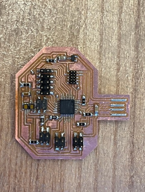
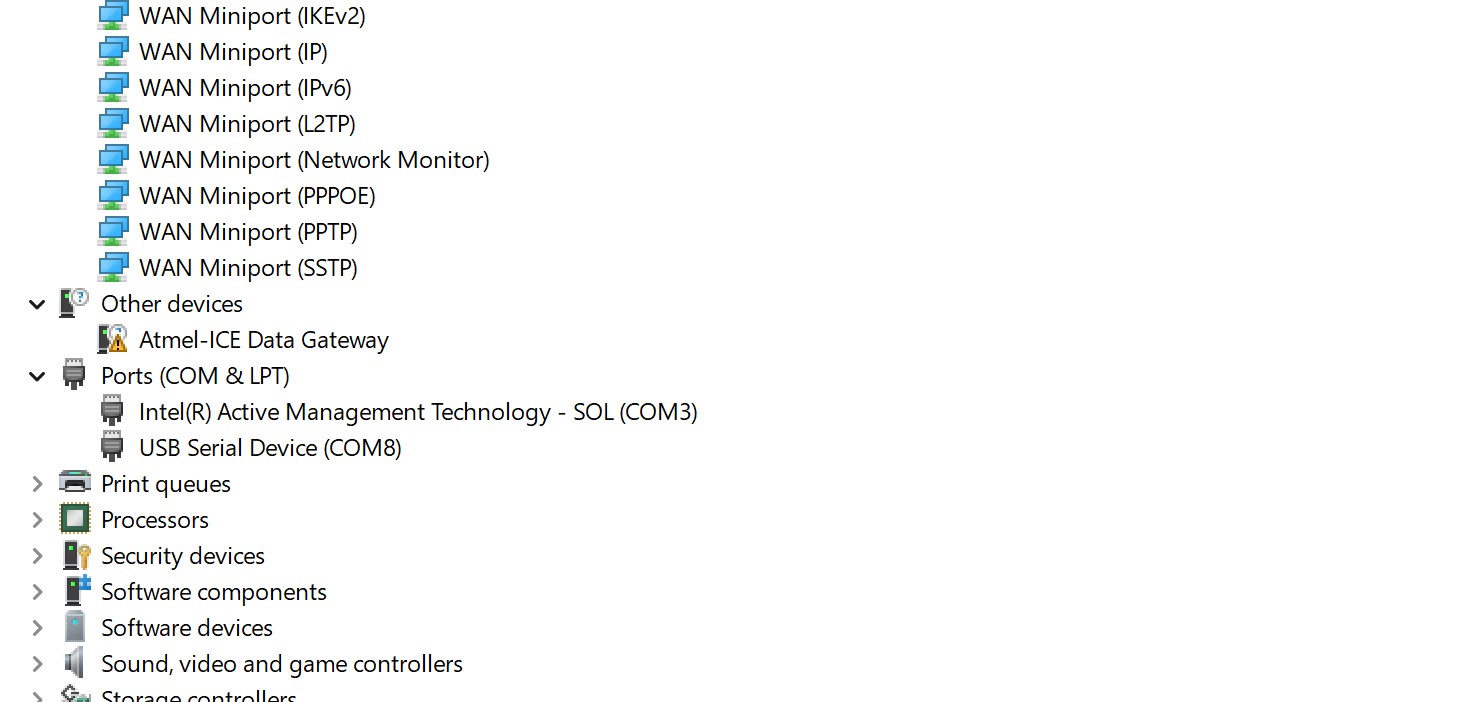
I confirmed my device was boot loaded and connected properly to my computer using my device manager and Arduino.
Using my laser TOF, I used Neil's code (with the help of Quentin to fix the code), to confirm how well my sensor sensed the environment (i.e. my hand). The first video is the Serial Plotter (Arduino), giving a graph as the readout and showing how the line changes according to the input (the distance of my hand). The second video is the Serial Monitor, showing the numerical quantity of the distance in mm.