For my final project, I'm planning to make a mini-car that is controllable with a joystick. Therefore, I wanted to make two Bluetooth devices this week and make them communicate with each other. Depending on the orientation of the joystick, I'm hoping to control the car's motors (and correspondingly, its speed and orientation).
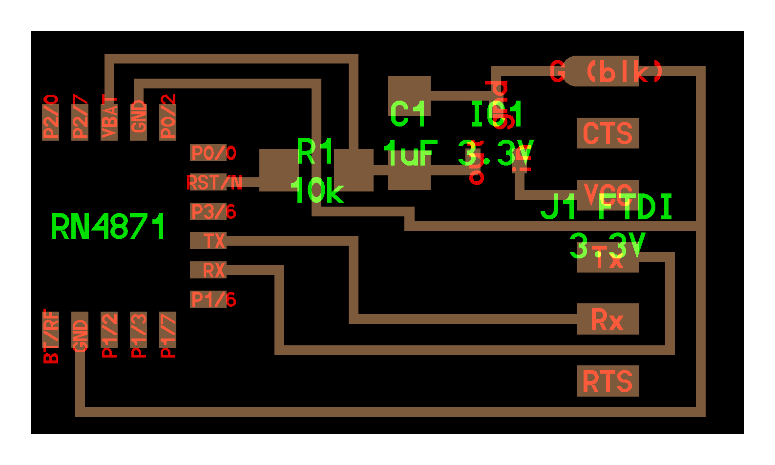
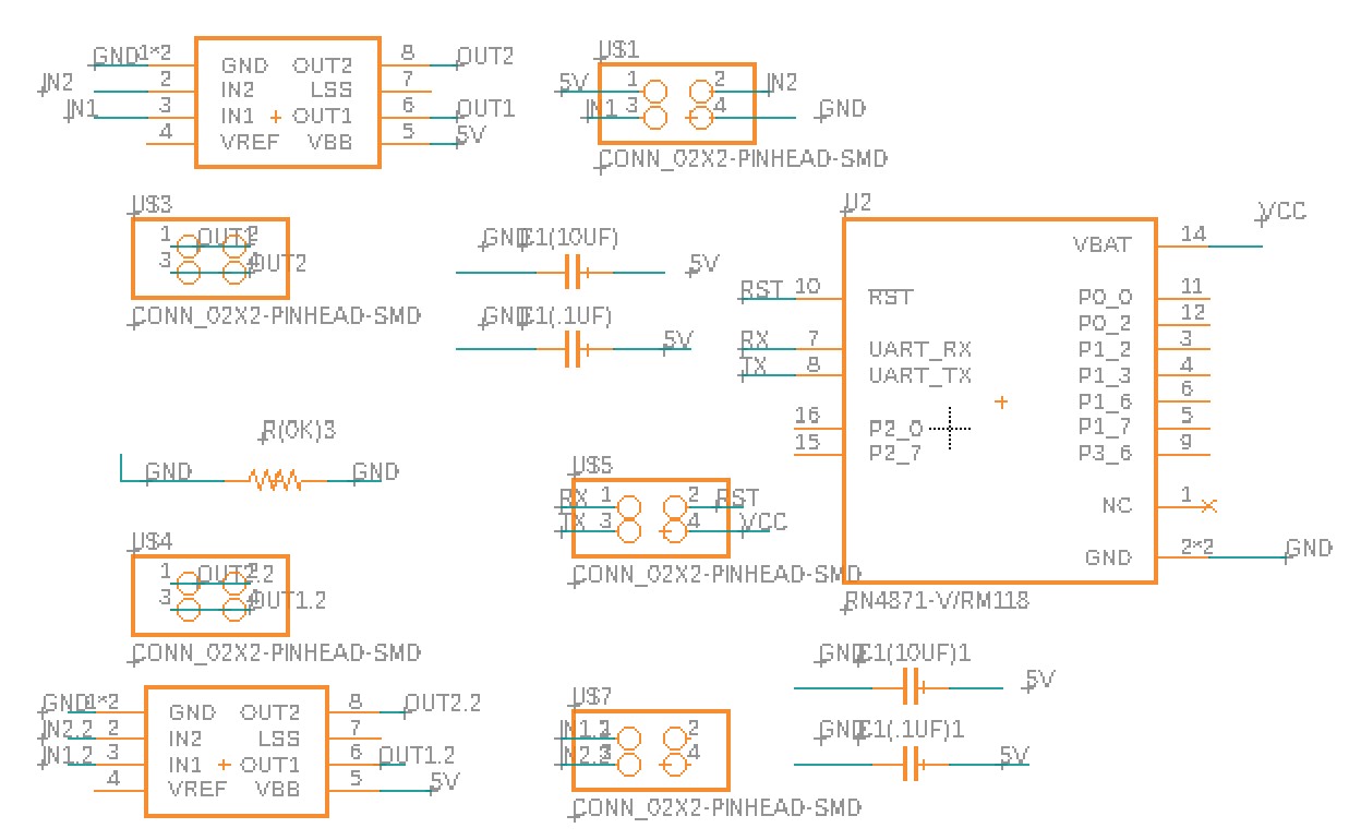
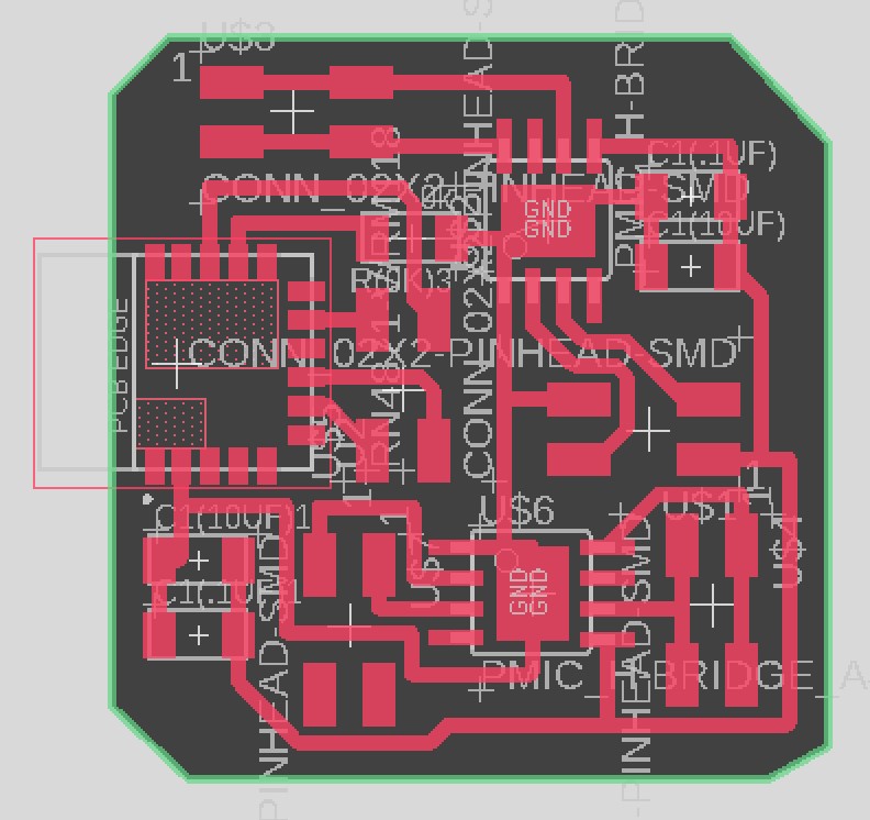
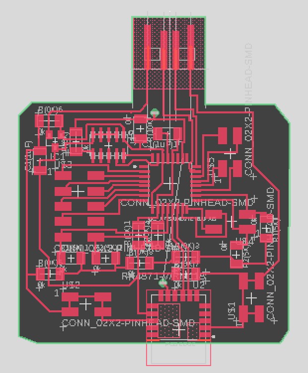
Since I was unfamiliar with making a wireless communicator, I referenced Neil's design that incorporates RN4871 2.4 GHz Bluetooth device. However, my design was different than Neil's because I wanted to 1) include two A4950 DC motor controller/pins for the car PCB while using PCB pins produced during week 9 and 2) make all the pins connect out for future use (i.e. honk) for the controller PCB. The design and schematic of both PCBs are shown below. During the design process, I made sure to include multiple capacitors for the car Bluetooth PCB and made the traces thicker (24mm instead of 12mm) because of the DC motors and high power requirement for the motors.
Bluetooth device for the car (schematic & design)
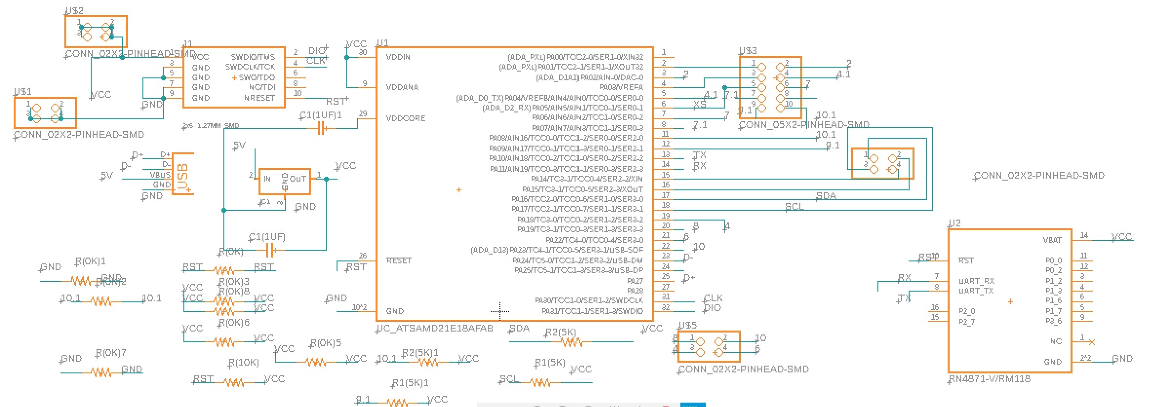
Bluetooth device for the controller (schematic & design)
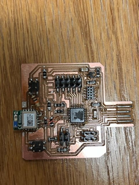
I used a hot air gun and soldering paste to attach the RN4871 Bluetooth device. It took me a while (~3hrs) to solder all the components because I wasn't familiar with using the soldering paste.
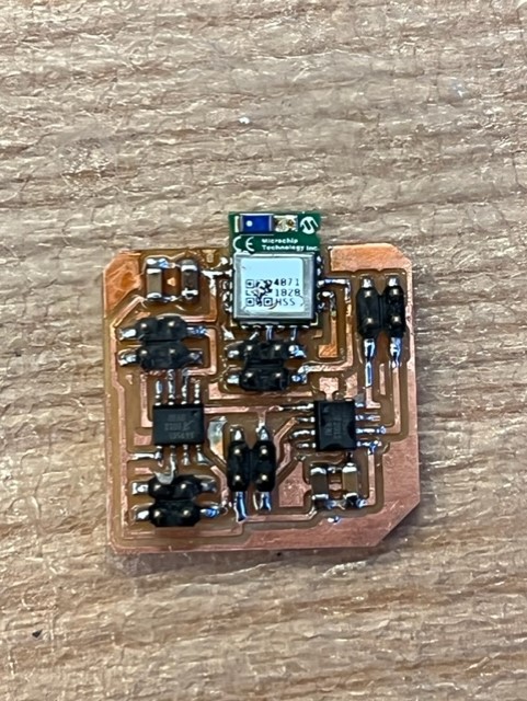
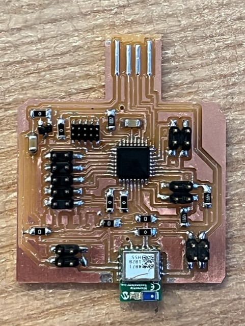
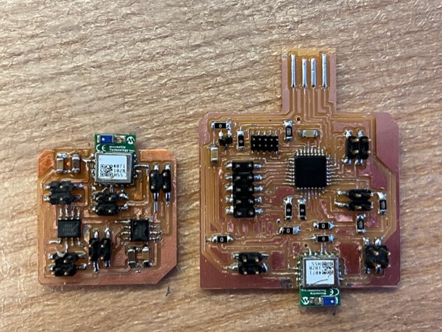
From left to right: car bluetooth PCB, controller bluetooth PCB, both
Bootloading was simple and successful!
However, throughout the debugging process, my PCB boards weren't working as intended. For the controller PCB, I added a pull-up resistor, but the board was still non-functional. Anthony helped me debug and we used the multimeter to check if any path was shorted. Luckily, this wasn't the problem. I realized that my Tx and Rx of the Bluetooth device weren't connected to the Rx and Tx of the microcontroller, respectively. Therefore, I used a magnetic wire to reroute the board. Unfortunately, when the board again didn't work, I tried using the connector pins and made Neil's RN4871 board. I hoped that this method would resolve my original board's issue, but since it's not working, I'm assuming that my microcontroller may be damaged or there's something else that's wrong with the board. Since this board will be part of my final project, I'll work with the TAs and Anthony to resolve the board.
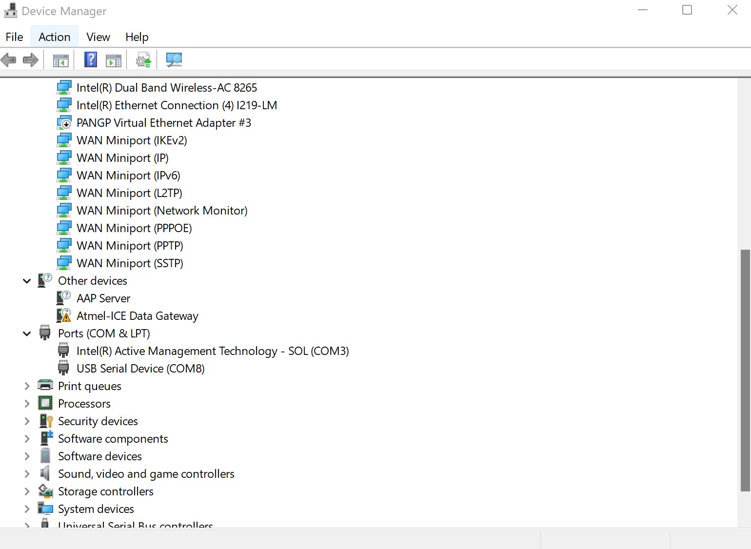
Unfortunately, I encountered a similar issue with my other board (car Bluetooth PCB), where my Bluetooth device wasn't recognized by Arduino. Anthony and I tried debugging the board, but we couldn't figure out what was wrong with the board. Anthony tried adding a pull-up resistor (though RN4871 should be internally pulled up) and a capacitor. Nonetheless, the car PCB didn't work (and the PCB design was checked multiple times), so we tried using Neil's board and the connector pins. Fortunately, the Bluetooth device was recognized by Arduino.
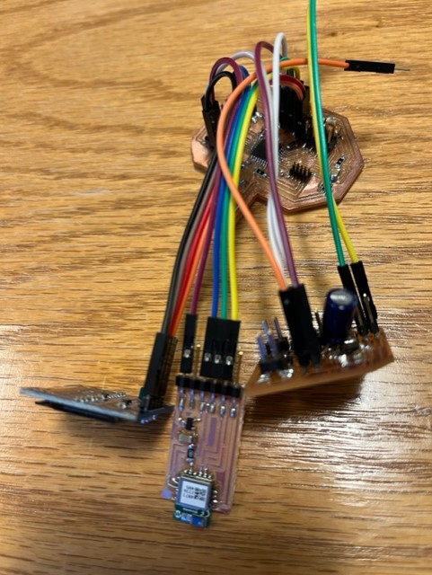
1) Controller PCB is still non-functional. 2) the car PCB is working after using Neil's pinned out board
|
|
To communicate between my car PCB and my phone, I used the BLE Scanner app. I first initialized my board on Aruidno (code attached below) and turned the device ON reference RN4871 datasheet/ commands. What Arduino Serial Monitor displayed during the car PCB - phone communication 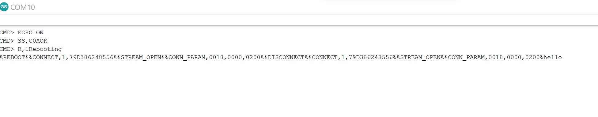
|