I had an amazing time designing my PCB using the Eagle software. It was my first time using Eagle but Anthony helped me to navigate through each component.
After importing the fab library (provided by the class to use the available components), I referenced ATSAMD11C
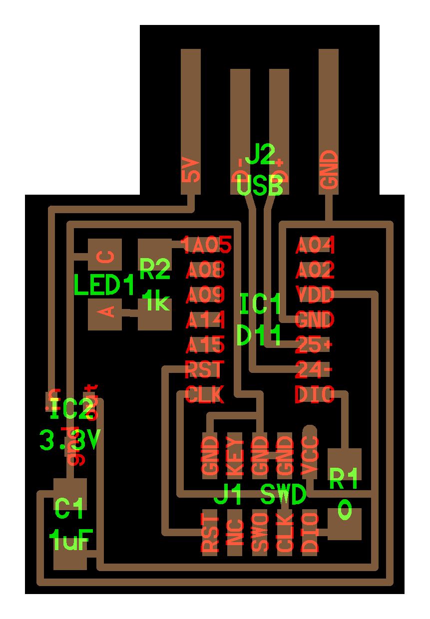
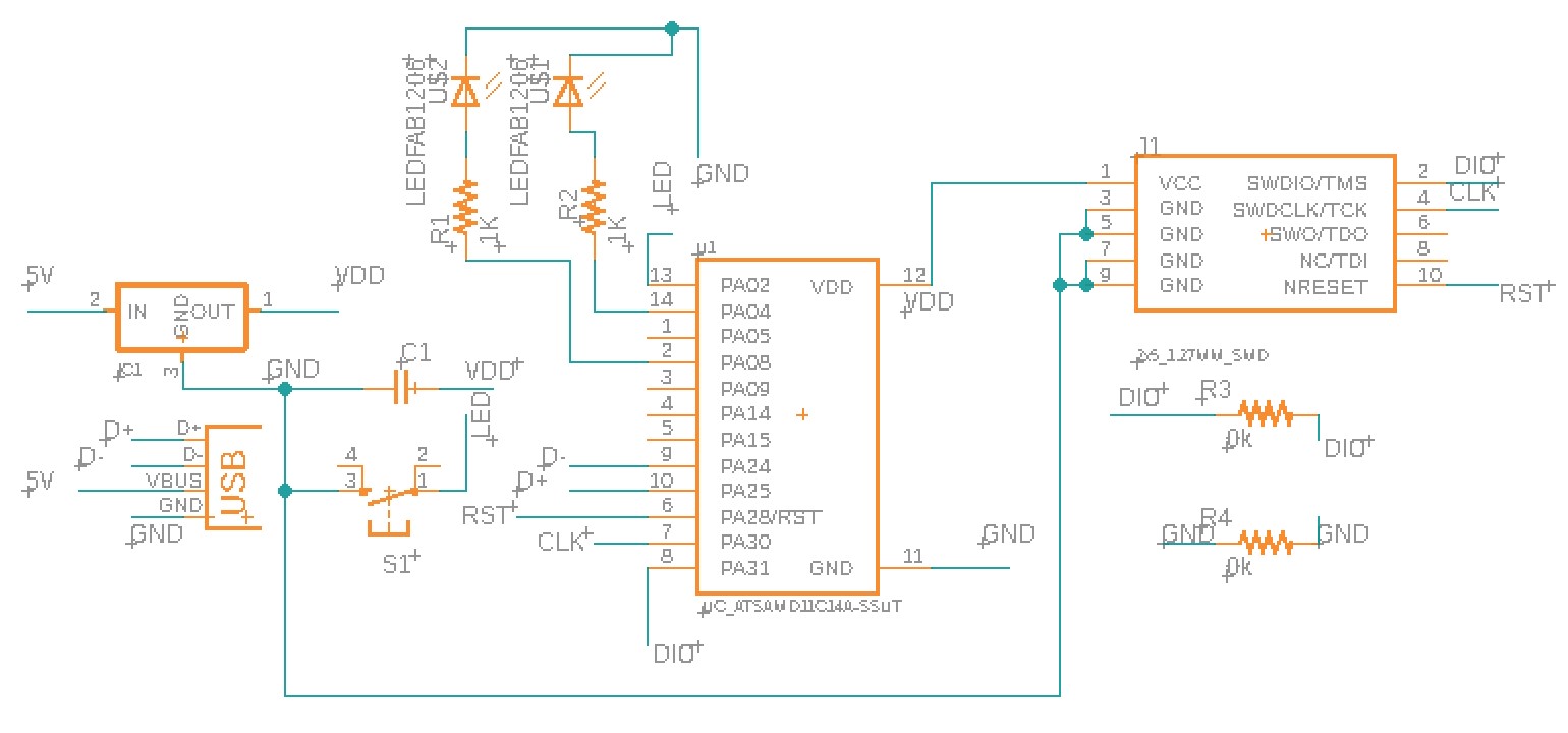
design to create my PCB. I first placed all the components (two LEDs (white and green), one microcontroller, one 3.3V voltage regulator, one USB port, one button switch, one 1uF capacitor, one connector, two 1Kohm resistors, and two 0ohm resistors) into the schematic.
I wanted to use green and blue LEDs but the inventory wasn't organized, so my LEDs ended up being green and white.
My first idea was to make a face with two LEDs as the character's eyes. However, while routing the components, I realized how difficult it was to draw glasses, nose, and mouth with all the parts I had.
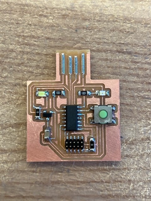
Unfortunately, I decided to keep my two LEDs, but make a more basic PCB that is rectangular. Nonetheless, connecting components was really enjoyable. On the schematic, instead of directly netting the parts, I used the "label" features
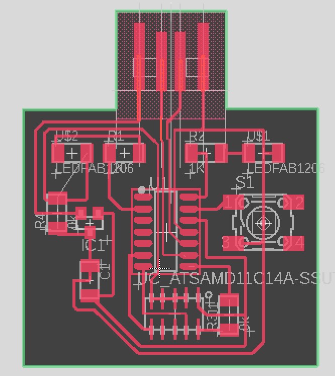
which allowed me to indicate that parts are associated with each other without creating a convoluted sketch. Afterward, I routed the parts using the net I previously formed, successfully producing my PCB design (shown below).
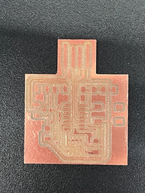
Similar to week 3 I downloaded the .brd file from my Eagle and used the Othermill to make my circuit. Again, a 1/64" bit was used to mill the circuit traces, and a 1/32" bit was used to mill the PCB outline. I used a vacuum and spatula to gently remove copper debris. Then, I soldered each component to the board. I'm proud of my improved soldering skill! I didn't make any mistakes this time:)
To test that my board is working as intended, I used the echo code provided by the class. After transferring the code to Arduino, I uploaded the code to the programmer. Using the "Serial Monitor" tool, I was able to interact with my PCB. It has the capacity to store 25 characters, and as shown in the video below, I tried tying various words and sentences. After the array with index 0 to 24 was filled, the programmer was overwritten starting from index 0.
Since my PCB already had two LEDs and a switch, I wanted to make it functional. I have never written C++ (Arduino), so with the help of Anthony, I explore various methods to make both LEDs turn ON when I pressed the switch. First, I set up three pin modes for two LEDs and my switch (I used pin mapping tables to reference each pin number). Then, within the loop, I indicated that when "digitalRead(button)==LOW" to turn on the LEDs (or HIGH). However, this resulted in LED that was ON only when the switch was pressed (aka. "grounded" or LOW). To resolve the following issue, I wrote a delay of 2000ms or 2s. However, I realized that the switch changed every 2s and I needed to time it very wisely in order to turn the light ON and OFF. Moreover, if I didn't time the press properly (or didn't press the switch for more than 2 seconds), then the LEDs were always ON.
To ensure that LEDs turned on ONLY when the switch was pressed, I needed to store the previous state of the switch, because I was only looking at the current state. Therefore, I initialized three variables (count, current state, and previous state). The count was used for tracking whether the LEDs were ON=1 or OFF=0, and the previous state and current state were used to monitor the state of the switch buttons (0 means the switch is grounded and 1 means there's voltage through the switch). I wrote three if statements, which were used to 1) turn ON the LEDs if they weren't ON previously and the button was pressed, 2) turn OFF the LEDs if they were ON previously when the button was pressed, and 3) update the current and previous state when the button is not pressed in preparation for the future when the button is being pressed. Refer to the Arduino code!